

SERVICE MANUAL
■ CONTENTS
TO SERVICE PERSONNEL . . . . . . . . . . . . . . . . . . . . 1
FRONT AND REAR PANELS . . . . . . . . . . . . . . . 1 – 2
SPECIFICATIONS . . . . . . . . . . . . . . . . . . . . . . . . . . . . 3
INTERNAL VIEW . . . . . . . . . . . . . . . . . . . . . . . . . . . . . 4
DISASSEMBLY PROCEDURES . . . . . . . . . . . . . . . . . 5
100778
SERVICE MANUAL
YST-MS50 (M)
POWERED MULTIMEDIA SPEAKERS
PRINTED CIRCUIT BOARD . . . . . . . . . . . . . . . . 6 – 8
BLOCK DIAGRAM . . . . . . . . . . . . . . . . . . . . . . . . . . . . 9
SCHEMATIC DIAGRAM . . . . . . . . . . . . . . . . . . . . . . 10
PARTS LIST . . . . . . . . . . . . . . . . . . . . . . . . . . . 11 – 15
PARTS LIST FOR CARBON RESISTORS . . . . . . . . 16
The contents of this Service Manual are applicable to the products with serial numbers of Z200001 and up.
YST-MS50
(M)
This manual has been provided for the use of authorized YAMAHA Retailers and their service personnel.
It has been assumed that basic service procedures inherent to the industry, and more specifically YAMAHA Products, are already
known and understood by the users, and have therefore not been restated.
WARNING: Failure to follow appropriate service and safety procedures when servicing this product may result in personal
injury, destruction of expensive components, and failure of the product to perform as specified. For these
reasons, we advise all YAMAHA product owners that any service required should be performed by an
authorized YAMAHA Retailer or the appointed service representative.
IMPORTANT: The presentation or sale of this manual to any individual or firm does not constitute authorization, certification
or recognition of any applicable technical capabilities, or establish a principle-agent relationship of any
form.
The data provided is believed to be accurate and applicable to the unit(s) indicated on the cover. The research, engineering, and
service departments of YAMAHA are continually striving to improve YAMAHA products. Modifications are, therefore, inevita-
ble and specifications are subject to change without notice or obligation to retrofit. Should any discrepancy appear to exist, please
contact the distributor's Service Division.
WARNING: Static discharges can destroy expensive components. Discharge any static electricity your body may have
accumulated by grounding yourself to the ground buss in the unit (heavy gauge black wires connect to this
buss).
IMPORTANT: Turn the unit OFF during disassembly and part replacement. Recheck all work before you apply power to the
unit.
IMPORTANT NOTICE
BASS
0 10
SPEAKERS
MULTIMEDIA
POWERED
YST-MS50
POWERED MULTIMEDIA SPEAKERS
VOLUME
YST-MS50(M)
YST-MS50
(M)
■ TO SERVICE PERSONNEL
1. Critical Components Information
Components having special characteristics are marked Z
and must be replaced with parts having specifications equal
to those originally installed.
2. Leakage Current Measurement (For 120V Models Only)
When service has been completed, it is imperative to verify
that all exposed conductive surfaces are properly insulated
from supply circuits.
● Meter impedance should be equivalent to 1500 ohm shunted
by 0.15µF.
AC LEAKAGE
TESTER OR
EQUIVALENT
EQUIPMENT
UNDER TEST
INSULATING
TABLE
WALL
OUTLET
WARNING: CHEMICAL CONTENT NOTICE!
The solder used in the production of this product contains LEAD. In addition, other electrical/electronic and/or
plastic (where applicable) components may also contain traces of chemicals found by the California Health and
Welfare Agency (and possibly other entities) to cause cancer and/or birth defects or other reproductive harm.
DO NOT PLACE SOLDER, ELECTRICAL/ELECTRONIC OR PLASTIC COMPONENTS IN YOUR MOUTH FOR
ANY REASON WHATSOEVER!
Avoid prolonged, unprotected contact between solder and your skin! When soldering, do not inhale solder fumes
or expose eyes to solder/flux vapor!
If you come in contact with solder or components located inside the enclosure of this product, wash your hands
before handling food.
1
■ FRONT AND REAR PANELS
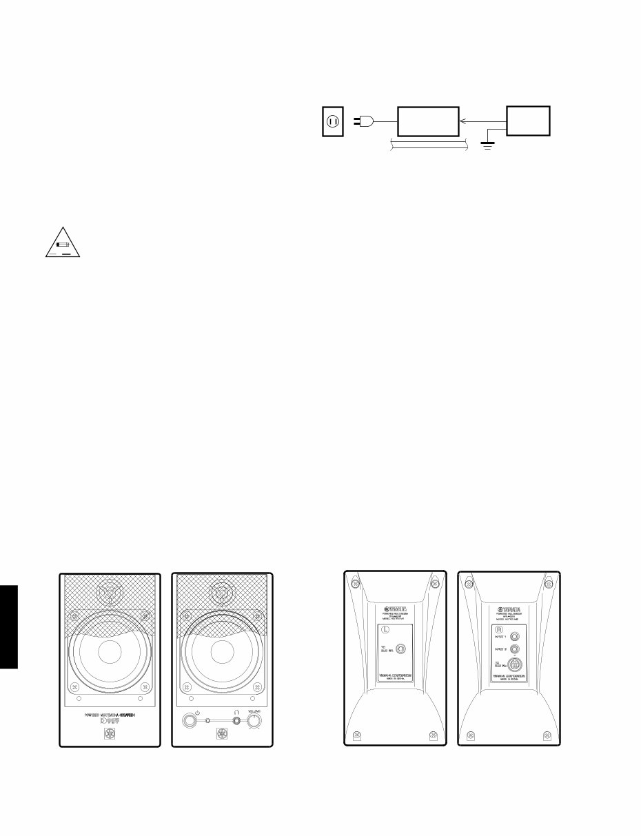
● Leakage current must not exceed 0.5mA.
● Be sure to test for leakage with the AC plug in both
polarities.
▼ Satellite Speakers Front Panel ▼ Satellite Speakers Rear Panel
Lch Rch Lch Rch
“CAUTION”
“F1 : FOR CONTINUED PROTECTION AGAINST RISK OF FIRE, REPLACE ONLY WITH SAME TYPE 2.0A, 250V FUSE.”
CAUTION
F1 : REPLACE WITH SAME TYPE 2.0A, 250V FUSE.
ATTENTION
F1 : UTILISER UN FUSIBLE DE RECHANGE DE MEME TYPE DE 2.0A, 250V.
A V
YST-MS50(M)
YST-MS50
(M)
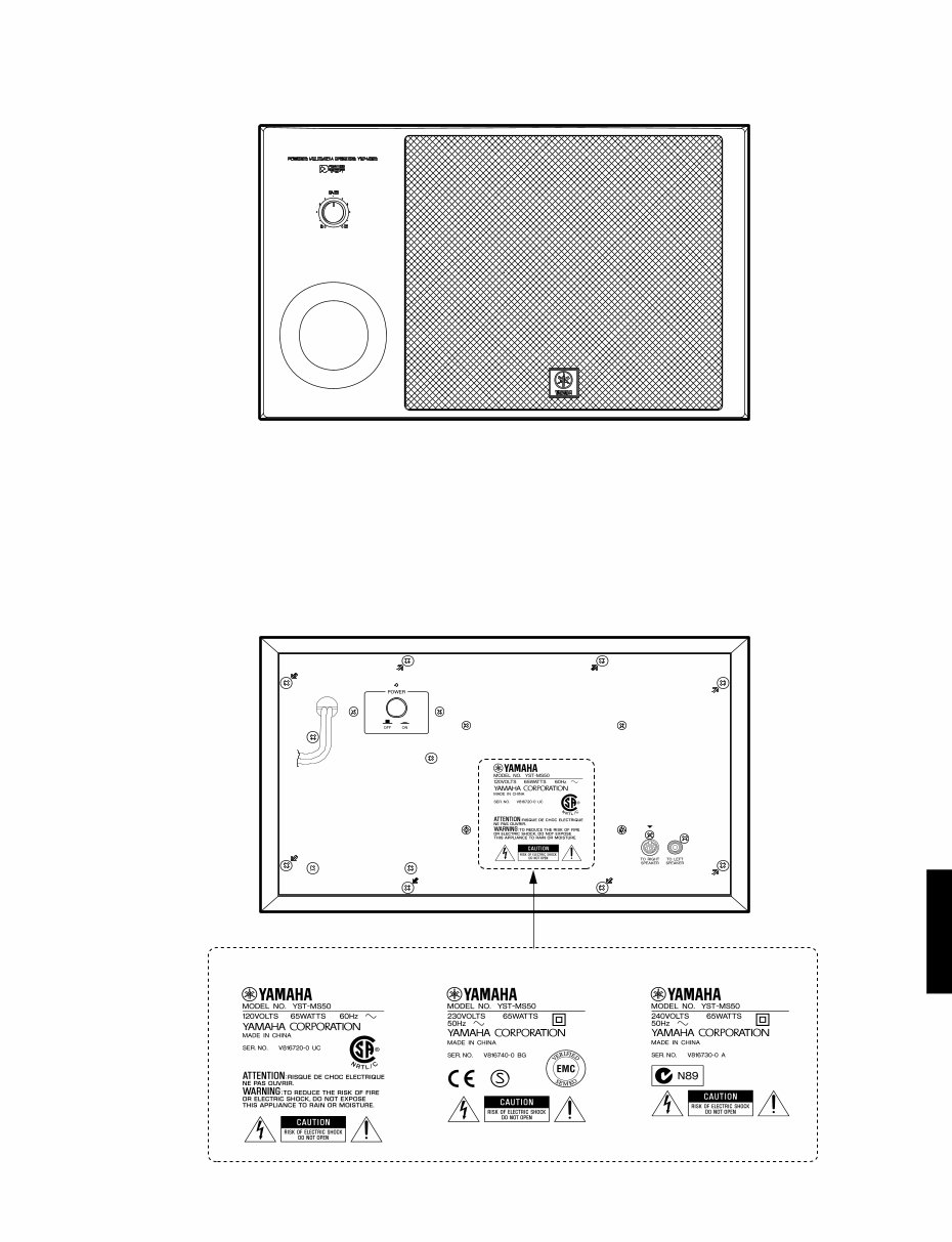
▼ Subwoofer Front Panel
2
▼ Subwoofer Rear Panel
U and C models A model B and G models
YST-MS50(M)
YST-MS50
(M)
■ SPECIFICATIONS
Type ................................. Advanced Active Servo Technology
Output Power
Satellite ................. 20W+20W (1kHz, 4 ohms at T.H.D.=10%)
Subwoofer ................... 40W (100Hz, 5 ohms at T.H.D.=10%)
Input Sensitivity ...................... 200mV (1kHz, 4 ohms at 20W)
Input Impedance ....................................................... 25 kohms
Frequency Response .................................... 32 Hz to 20 kHz
Driver
Satellite
Tweeter ................................... 19mm (3/4") balanced dome
Magnetic shielding type
Midrange ........................................................ 8cm (3") cone
Magnetic shielding type
Subwoofer ................................................. 16cm (6-1/2") cone
Magnetic shielding type
Power Consumption ........................................................ 65 W
Power Supply
U, C models .................................................... AC120V, 60 Hz
A model ........................................................... AC240V, 50 Hz
B, G models .................................................... AC230V, 50 Hz
Dimensions (W X H X D)
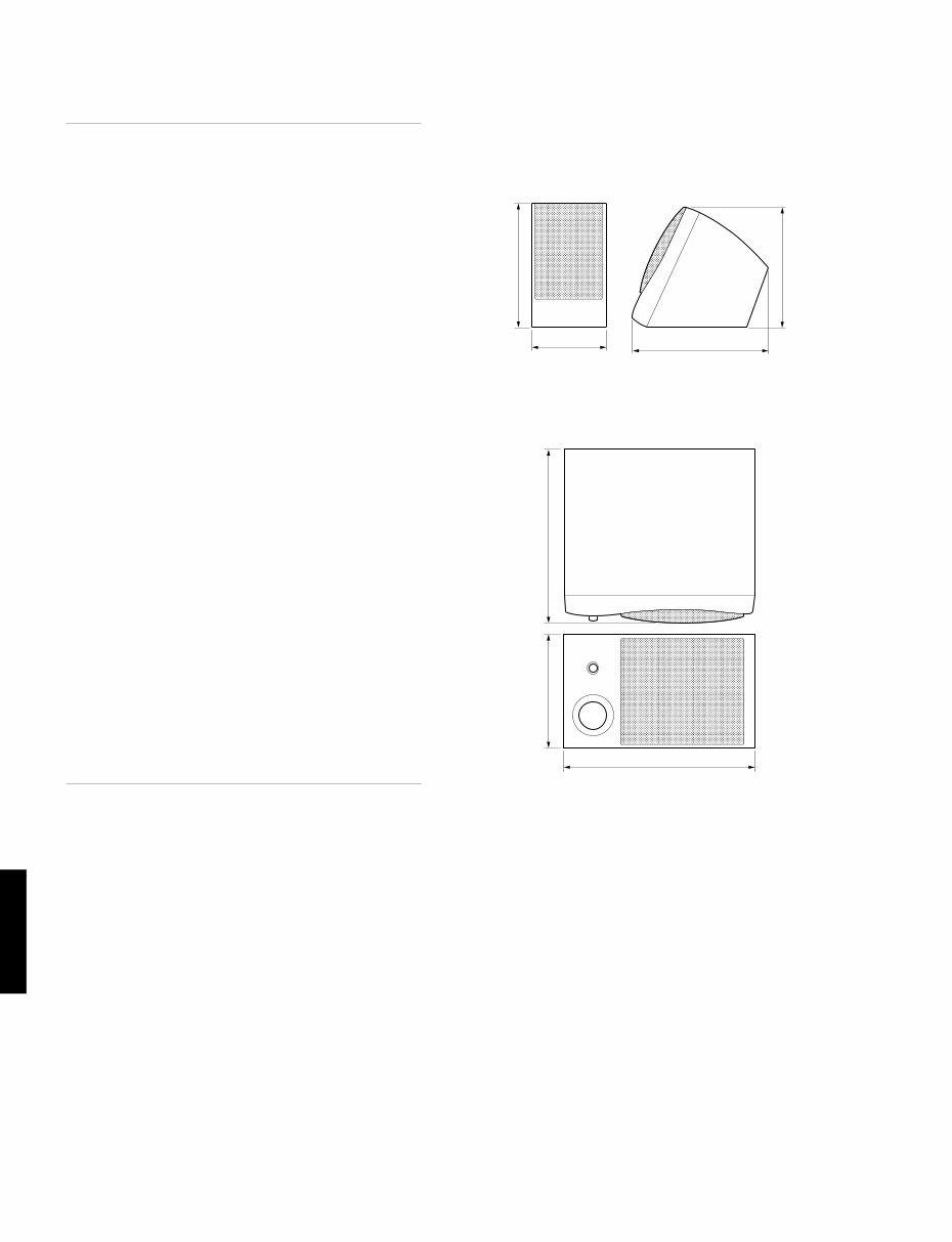
Satellite ..................................................... 97 x 159 x 178 mm
(3-13/16" x 6-1/4" x 7")
Subwoofer .............................................. 350 x 210 x 321 mm
(13-3/4" x 8-1/4" x 12-5/8")
Weight
Satellite ................................................ 0.7 kg (1 lbs. 9 oz) x 2
Subwoofer ................................................ 8 kg (17 lbs. 10 oz)
Finish ....................................................................... White color
Black color
Accessories
3.5mm stereo mini plug cable (1.8m) x 1
RCA pin plug cable (1.8m) x 1
8 pin plug cable (1.8m) x 1
8 pcs of nonskid pad x 1set
* Specifications subject to change without notice.
● Satellite Speaker
U . . . . . . . . . . . . . USA model
C . . . . . . . . . Canadian model
A . . . . . . . . Australian model
B . . . . . . . . . . . British model
G . . . . . . . . . European model
3
Unit : mm (inch)
● DIMENSIONS
97 (3-13/16") 178 (7")
166(6-17/32")
159 (6-1/4")
● Subwoofer
210 (8-1/4") 321 (12-5/8")
350 (13-3/4")
YST-MS50(M)
YST-MS50
(M)
■ INTERNAL VIEW
4
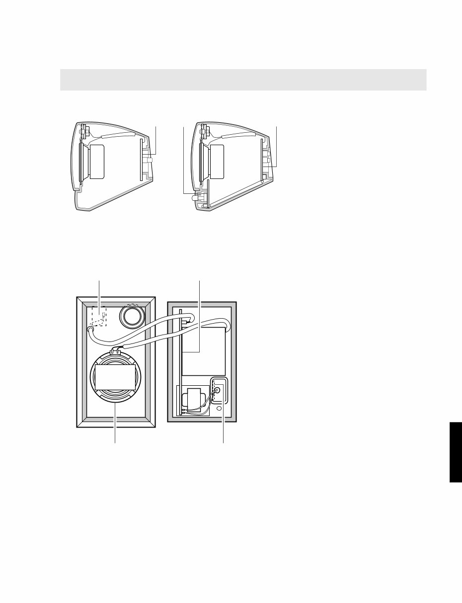
▼ Satellite Speakers
▼ Subwoofer
w q e
r
y u
t
Note: The Satellite Speakers are available by the speaker unit (L ch or R ch).
Individual parts of the Satellite Speakers are not available. (See page 14 and 15 of the PARTS LIST.)
Satellite Speaker (L ch)
q MAIN (B) P.C.B.
Satellite Speaker (R ch)
w MAIN (C) P.C.B.
e MAIN (D) P.C.B.
Lch Rch
Subwoofer
r MAIN (E) P.C.B.
t MAIN (A) P.C.B.
y SPEAKER UNIT
(Subwoofer)
u MAIN (F) P.C.B.
YST-MS50(M)
YST-MS50
(M)
■ DISASSEMBLY PROCEDURES
(Remove parts in the order as numbered.)
Fig. 2
Fig. 1
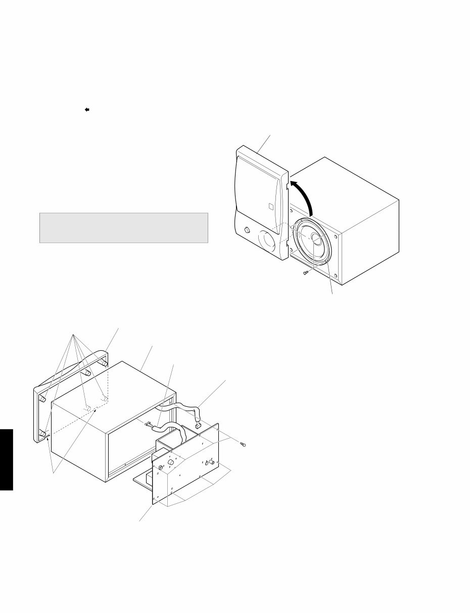
● Disassemble of the Subwoofer
1. Removal of the Rear Panel Ass’y.
a. Remove 8 screws ( q ) in Fig. 1, and remove the
rear panel ass’y.
* Arrow marks ( ) are printed to identify the screws to be
removed.
b. Disconnect one connector in Fig. 1.
c. Disconnect the Speaker cord in Fig. 1.
* When assembling the Rear Panel Ass'y, check to ensure
that the packing is not damaged so as to prevent air leak-
age from occurring.
2. Removal of the Front Panel Ass’y
The front panel assy is fixed to the cabinet with
dowels at 6 locations.
* As a screwdriver (for slotted head screw) is used
for removal, use special care not to cause damage
to the Cabinet.
a. Using the screwdriver insert in the gaps between the
front panel ass’y and cabinet (bottom side first), push
up the front panel ass’y.
b. Remove the front panel ass’y while taking it out.
(Front panel ass’y can not to remove completely.)
3. Removal of the Speaker
a. Set up the front panel ass’y in the direction of the
arrow, in Fig. 2.
b. Remove 4 screws ( w ) in Fig. 2, and remove the
speaker.
Dowels
Front Panel Ass’y
Cabinet
Connector
Gaps
Speaker Cord
Rear Panel Ass’y
Speaker
Front Panel Ass’y
q
w
5
A B C D E F G H
1
2
3
4
5
6
YST-MS50(M)
6 7
MAIN ( A ) P. C. B.
TO : SPEAKER (WOOFER)
FROM : POWER CORD
WH
BE
FROM : MAIN ( F )
FROM : MAIN ( E )
TO RIGHT
SPEAKER
TO LEFT
SPEAKER
RE
WH
WH: U, C
BE: A, B, G
BL: U, C
BR: A, B, G
MAIN ( E ) P. C. B.
BASS
TO : MAIN ( A )
MAIN ( F ) P. C. B.
POWER
WH
BE
TO : MAIN ( A )
MAIN ( B ) P. C. B.
TO
SUB Wo.
L
+ – + –
2.2µ
SPEAKER
(MIDRANGE)
SPEAKER
(TWEETER)
BL
RE
RE
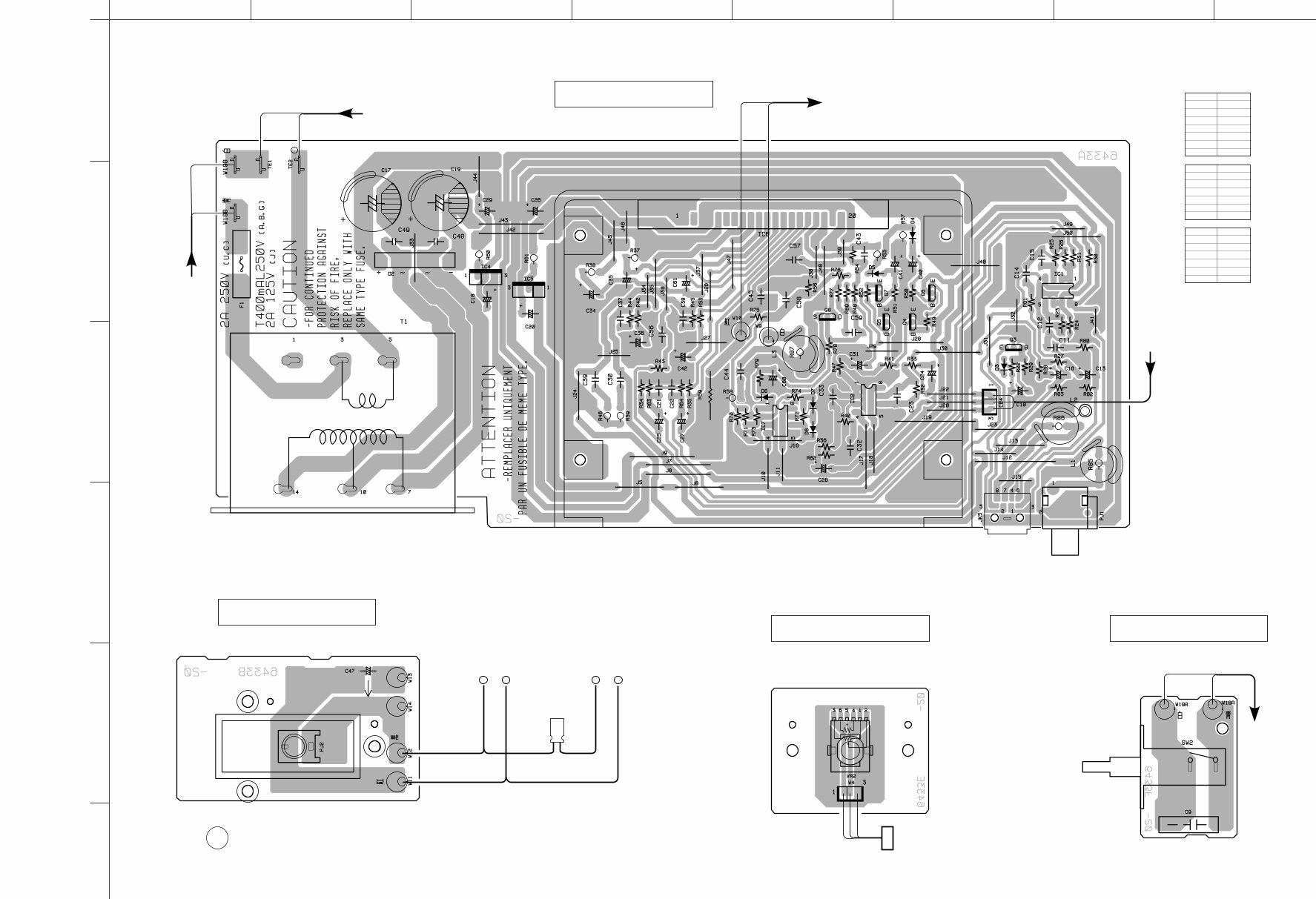
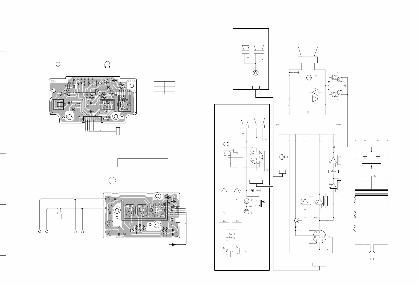
■ PRINTED CIRCUIT BOARD (Component side)
▼ Satellite Speaker (L ch)
▼ Subwoofer
Ref. No. Location
D2 B2
D3 F3
D4 F2
D5 E2
D6 E3
D7 E3
D8 E3
Ref. No. Location
IC1 F2
IC2 E3
IC4 C2
IC5 C2
IC6 E2
IC7 E3
● Semiconductor Location
Ref. No. Location
Q3 F3
Q4 F2
Q5 E2
Q6 F2
Q7 E2
Q8 E2
A B C D E F G H
1
2
3
4
5
6
YST-MS50(M)
■ BLOCK DIAGRAM
8 9
MAIN ( C ) P. C. B.
TO : MAIN ( D )
VOLUME
(HEADPHONE) (POWER)
2
1
7
5
8
4
3
6
MAIN ( D ) P. C. B.
TO
SUB Wo.
INPUT2
INPUT1
R
+ –
+ –
2.2µ
SPEAKER
(MIDRANGE)
SPEAKER
(TWEETER)
RE
BL
RE
FROM : MAIN ( C )
Q2
Q3
Q8
SW1
POWER
SW2
F1
D2
IC4
GND
IN
+
–
OUT
IC5
GND
IN
OUT
~
POWER
TRANSFORMER
Regulator
(POWER)
Q1
3
5
VOLUME
VR1
VR2
IR
JK4
INPUT 1
INPUT 2
JK3
Rch SATELLITE SPEAKER
Lch SATELLITE SPEAKER
IL
3
1
G
4
7
6
JK2
8
2
5
+12
+12
+12
PWS
TO
SUB Wo.
TO LEFT
SPEAKER
TO RIGHT
SPEAKER
OL
1
7
IC3
(NJM4556AL)
OR
RSP–
RSP+
TWEETER
MIDRENGE
+
+
JK1
(HEADPHONE)
–
–
TWEETER
MIDRENGE
+
+
–
–
SUBWOOFER
SP+
SP–
E
–12
3
1
G
4
7
6
8
2
5
+12
E
OL
PWS
OR
RSP–
RSP+
JK5
–12
–12
3
5
–12
–12
+12
+12
1
7
H. P. F
12dB/oct
H. P. F
12dB/oct
–12
+12
–6dB/oct
–12
+12
–12dB/oct
EQ Amp
IC1,2
(NJM4558D)
Mute
Power Amp.
IC6
(STK408-040E)
IC1
IC2
IC2
IC1
IC7
IC7
(NJM4558D)
+12
–12
2
7
20
1
18
+12
1
6
–12
6
+12
7
–12
3
17
SWI
SRI
SLI
PWS1
RSP+
LSP+
PJ1
TO
SUB Wo.
PJ2
16
12
14
9
8
5
3
1
+B
–B
–B
+B
BASS
Rectifier
Q6
Q7
Q5
Q4
~
A. N. I. C
ON
OFF
■ PRINTED CIRCUIT BOARD (Component side)
▼ Satellite Speaker (R ch)
Ref. No. Location
IC3 B2
Q1 B2
Q2 B2
● Semiconductor Location
A B C D E F G H
1
2
3
4
5
6
I J K
7
8
YST-MS50(M)
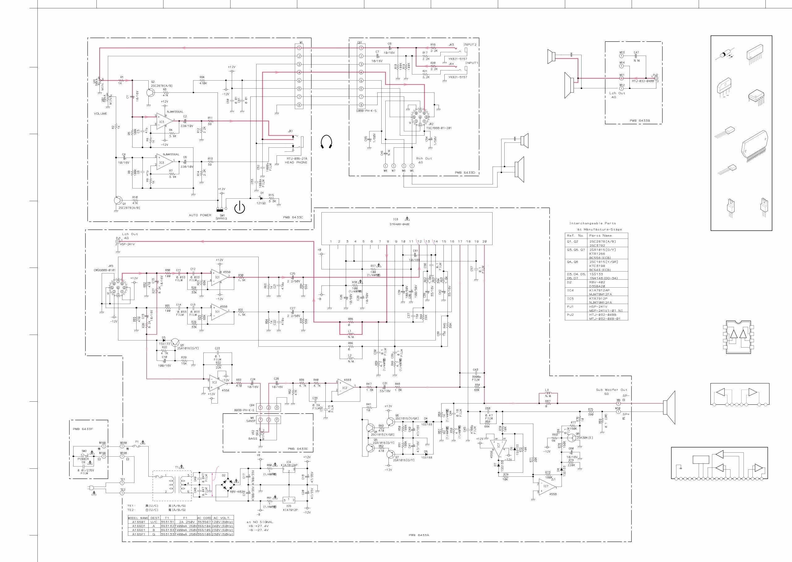
■ SCHEMATIC DIAGRAM
* All voltage are measured with a 10MΩ/V DC electric volt meter.
* Components having special characteristics are marked Z and
must be replaced with parts having specifications equal to those
originally installed.
* Schematic diagram is subject to change without notice.
10
IC1, 2, 7 : NJM4558D
Dual OP-Amp
IC3 : NJM4556AL
Dual OP-Amp
–IN1
2
+IN1
3
–VCC
4
+IN2
5
–IN2
6
OUT2
7
+VCC
8
OUT1
1
–
+
–
+
IC6 : STK408-040E
3 Channels AF Power Amp
20 19 18 17 16 15 14 13 12 11 10 9 8 7 6 5 4 3 2 1
THERMAL
SENSOR
SUB CH.1
–
+
CH.3
–
+
–
+
CH.2
SUB GND
N. C.
CH.2 –VCC
CH.1 –VCC
CH.1,2,3 +VCC
CH.1 OUT
CH.2 OUT
PRE –VCC
PRE +VCC
CH.1 IN
CH.1 NF
C. C. C. BIAS
CH.2 NF
CH.2 IN
CH.3 NF
CH.3 IN
CH.2 –VCC
CH.3 OUT
LIMITER
A.N.I.C
POWER AMP
LPF
HPF
PHONE AMP
POWER SUPPLY
0
0
0
0
0
0
11.7
0
0
0
-11.5
0
0
0
11.4 11.7 11.4
10.4
0
0
0
11.7
0
0
0
-11.5
0
0
0
-11.5
0
0
0
11.7
0
-27.1
-0.2
-0.2
-0.1
-0.1
-24.3
-0.1
-0.1
25.6
-25.5
0
0
27.1
-27.1
-27.1
0
0 0
0 0
0
0 0
0
0
0
0
0
0
11.7
-11.5
-1.5
0
0
0
0
0
0 0
0
0
0
0.2
-11.5
0.2
0
11.7
11.7
0
27.1
-11.5
0
-27.1
-27.1
AC43.2
27.1
+
–
+
–
SATELLITE
MIDRANGE
L ch
SATELLITE
TWEETER
L ch
2.2µ
+
–
+
–
SATELLITE
MIDRANGE
R ch
SATELLITE
TWEETER
R ch
2.2µ
RE BL
TO
SUB Wo.
(HEADPHONE)
TO RIGHT
SPEAKER
TO LEFT
SPEAKER
MAIN (C)
VOLUME
(POWER)
INPUT 2
INPUT 1
WOOFER
+
–
MAIN ( D )
RE
BL
MAIN ( B )
TO
SUB Wo.
MAIN ( F )
POWER MAIN ( E )
BASS
MAIN ( A )
WH
RE
BE
WH
BL
WH
BR
BE
ON OFF
NJM4556AL
NJM4558D
1SS133
Anode
Cathode
B
C
E
2SA1015 (O, Y)
2SC1815 (Y, GR)
2SC2878 (A, B)
RBV-402
D
G
S
NJM78M12FA
STK408-040E
PIN CONNECTION DIAGRAM OF TRAN-
SISTORS, DIODES AND ICS.
+
–
2SK304 (E)
1
20
1: OUTPUT
2: COMMON
3: INPUT 3
2
1
NJM79M12FA
1:COMMON
2:INPUT
3:OUTPUT 3
2
1
1
4
8
1
8
– +
OUT1
–IN1
–VCC
+VCC
OUT2
1
2
3
4 5
+IN1 –IN2
+IN2
–+
6
7
8

YST-MS50(M)
YST-MS50
(M)
11
ABBREVIATIONS IN THIS LIST ARE AS FOLLOWS :
C.A.EL.CHP : CHIP ALUMI. ELECTROLYTIC CAP
C.CE : CERAMIC CAP
C.CE.ARRAY : CERAMIC CAP ARRAY
C.CE.CHP : CHIP CERAMIC CAP
C.CE.ML : MULTILAYER CERAMIC CAP
C.CE.M.CHP : CHIP MULTILAYER CERAMIC CAP
C.CE.SAFTY : RECOGNIZED CERAMIC CAP
C.CE.TUBLR : CERAMIC TUBULAR CAP
C.CE.SMI : SEMI CONDUCTIVE CERAMIC CAP
C.EL : ELECTROLYTIC CAP
C.MICA : MICA CAP
C.ML.FLM : MULTILAYER FILM CAP
C.MP : METALLIZED PAPER CAP
C.MYLAR : MYLAR FILM CAP
C.MYLAR.ML : MULTILAYER MYLAR FILM CAP
C.PAPER : PAPER CAPACITOR
C.PLS : POLYSTYRENE FILM CAP
C.POL : POLYESTER FILM CAP
C.POLY : POLYETHYLENE FILM CAP
C.PP : POLYPROPYLENE FILM CAP
C.TNTL : TANTALUM CAP
C.TNTL.CHP : CHIP TANTALUM CAP
C.TRIM : TRIMMER CAP
CN : CONNECTOR
CN.BS.PIN : CONNECTOR, BASE PIN
CN.CANNON : CONNECTOR, CANNON
CN.DIN : CONNECTOR, DIN
CN.FLAT : CONNECTOR, FLAT CABLE
CN.POST : CONNECTOR, BASE POST
COIL.MX.AM : COIL, AM MIX
COIL.AT.FM : COIL, FM ANTENNA
COIL.DT.FM : COIL, FM DETECT
COIL.MX.FM : COIL, FM MIX
COIL.OUTPT : OUTPUT COIL
DIOD.ARRAY : DIODE ARRAY
DIODE.BRG : DIODE BRIDGE
DIODE.CHP : CHIP DIODE
DIODE.VAR : VARACTOR DIODE
DIOD.Z.CHP : CHIP ZENER DIODE
DIODE.ZENR : ZENER DIODE
DSCR.CE : CERAMIC DISCRIMINATOR
FER.BEAD : FERRITE BEADS
FER.CORE : FERRITE CORE
FET.CHP : CHIP FET
FL.DSPLY : FLUORESCENT DISPLAY
FLTR.CE : CERAMIC FILTER
FLTR.COMB : COMB FILTER MODULE
FLTR.LC.RF : LC FILTER ,EMI
GND.MTL : GROUND PLATE
GND.TERM : GROUND TERMINAL
HOLDER.FUS : FUSE HOLDER
IC.PRTCT : IC PROTECTOR
JUMPER.CN : JUMPER CONNECTOR
JUMPER.TST : JUMPER, TEST POINT
L.DTCT : LIGHT DETECTING MODULE
Note) Those parts marked with “#” are not included in the P.C.B. ass'y.
L.EMIT : LIGHT EMITTING MODULE
LED.DSPLY : LED DISPLAY
LED.INFRD : LED, INFRARED
MODUL.RF : MODULATOR, RF
PHOT.CPL : PHOTO COUPLER
PHOT.INTR : PHOTO INTERRUPTER
PHOT.RFLCT : PHOTO REFLECTOR
PIN.TEST : PIN, TEST POINT
PLST.RIVET : PLASTIC RIVET
R.ARRAY : RESISTOR ARRAY
R.CAR : CARBON RESISTOR
R.CAR.CHP : CHIP RESISTOR
R.CAR.FP : FLAME PROOF CARBON RESISTOR
R.FUS : FUSABLE RESISTOR
R.MTL.CHP : CHIP METAL FILM RESISTOR
R.MTL.FLM : METAL FILM RESISTOR
R.MTL.OXD : METAL OXIDE FILM RESISTOR
R.MTL.PLAT : METAL PLATE RESISTOR
RSNR.CE : CERAMIC RESONATOR
RSNR.CRYS : CRYSTAL RESONATOR
R.TW.CEM : TWIN CEMENT FIXED RESISTOR
R.WW : WIRE WOUND RESISTOR
SCR.BND.HD : BIND HEAD B-TITE SCREW
SCR.BW.HD : BW HEAD TAPPING SCREW
SCR.CUP : CUP TITE SCREW
SCR.TERM : SCREW TERMINAL
SCR.TR : SCREW, TRANSISTOR
SUPRT.PCB : SUPPORT, P.C.B.
SURG.PRTCT : SURGE PROTECTOR
SW.TACT : TACT SWITCH
SW.LEAF : LEAF SWITCH
SW.LEVER : LEVER SWITCH
SW.MICRO : MICRO SWITCH
SW.PUSH : PUSH SWITCH
SW.RT.ENC : ROTARY ENCODER
SW.RT.MTR : ROTARY SWITCH WITH MOTOR
SW.RT : ROTARY SWITCH
SW.SLIDE : SLIDE SWITCH
TERM.SP : SPEAKER TERMINAL
TERM.WRAP : WRAPPING TERMINAL
THRMST.CHP : CHIP THERMISTOR
TR.CHP : CHIP TRANSISTOR
TR.DGT : DIGITAL TRANSISTOR
TR.DGT.CHP : CHIP DIGITAL TRANSISTOR
TRANS : TRANSFORMER
TRANS.PULS : PULSE TRANSFORMER
TRANS.PWR : POWER TRANSFORMER ASS’y
TUNER.AM : TUNER PACK, AM
TUNER.FM : TUNER PACK, FM
TUNER.PK : FRONT-END TUNER PACK
VR : ROTARY POTENTIOMETER
VR.MTR : POTENTIOMETER WITH MOTOR
VR.SW : POTENTIOMETER WITH ROTARY SW
VR.SLIDE : SLIDE POTENTIOMETER
VR.TRIM : TRIMMER POTENTIOMETER
■ ELECTRICAL PARTS
PARTS LIST
■ WARNING
Components having special characteristics are marked Z and must be replaced
with parts having specifications equal to those originally installed.
● Carbon resistors (1/6W or 1/4W) are not included in the ELECTRICAL PARTS
List. For the parts No. of the carbon resistors, refer to last page.
You're Reading a Preview
What's Included?
 Lifetime Access
Fast Download Speeds
Online & Offline Access
Access PDF Contents & Bookmarks
Full Search Facility
Print one or all pages of your manual
$28.99
Yamaha YST-MS50 POWERED MULTIMEDIA SPEAKERS Service Manual
Viewed 71 Times Today

What's Included?
Lifetime Access
Fast Download Speeds
Online & Offline Access
Access PDF Contents & Bookmarks
Full Search Facility
Print one or all pages of your manual
$28.99

Secure transaction
What's Included?
Lifetime Access
Fast Download Speeds
Online & Offline Access
Access PDF Contents & Bookmarks
Full Search Facility
Print one or all pages of your manual
Description
This service manual for the Yamaha YST-MS50 Powered Multimedia Speakers is an essential resource for both professional mechanics and DIY enthusiasts. It provides detailed information on the front and rear panels, internal view, disassembly procedures, printed circuit board, block diagram, schematic diagram, and parts list, including the parts list for carbon resistors. The manual is in English and consists of 15 pages, available in a format suitable for both Windows and MAC platforms.


