SERVICE MANUAL DIGITAL SOUND PROJECTOR YSP-1100 ■ CONTENTS TO SERVICE PERSONNEL .......................................... 2 FRONT PANEL .............................................................. 3 REAR PANELS .............................................................. 3 REMOTE CONTROL PANELS ...................................... 4 SPECIFICATIONS / 参考仕様 ........................................ 5 INTERNAL VIEW ........................................................... 5 SET MENU TABLE / セットメニュー ............................ 6 SERVICE PRECAUTIONS / サービス時の注意事項 ..... 7 DISASSEMBLY PROCEDURES / 分解手順 ........... 7–13 UPDATING FIRMWARE / ファームウェアの書き込み ..................................... 14–24 SELF DIAGNOSIS FUNCTION (DIAG) / 自己診断機能(ダイアグ) ..................................... 25–42 DISPLAY DATA ........................................................... 43 IC DATA ................................................................. 44–45 BLOCK DIAGRAMS .............................................. 46–47 PRINTED CIRCUIT BOARDS ................................ 48–58 PIN CONNECTION DIAGRAM .................................... 59 SCHEMATIC DIAGRAMS ...................................... 61–68 REPLACEMENT PARTS LIST .............................. 69–93 REMOTE CONTROL .............................................. 94–95 ADJUSTING SYSTEM PARAMETERS / 拡張メニューを設定する ........................................ 96–98 101036 IMPORTANT NOTICE This manual has been provided for the use of authorized YAMAHA Retailers and their service personnel. It has been assumed that basic service procedures inherent to the industry, and more specifically YAMAHA Products, are already known and understood by the users, and have therefore not been restated. WARNING: Failure to follow appropriate service and safety procedures when servicing this product may result in personal injury, destruction of expensive components, and failure of the product to perform as specified. For these reasons, we advise all YAMAHA product owners that any service required should be performed by an authorized YAMAHA Retailer or the appointed service representative. IMPORTANT: The presentation or sale of this manual to any individual or firm does not constitute authorization, certification or recognition of any applicable technical capabilities, or establish a principle-agent relationship of any form. The data provided is believed to be accurate and applicable to the unit(s) indicated on the cover. The research, engineering, and service departments of YAMAHA are continually striving to improve YAMAHA products. Modifications are, therefore, inevitable and specifications are subject to change without notice or obligation to retrofit. Should any discrepancy appear to exist, please contact the distributor's Service Division. WARNING: Static discharges can destroy expensive components. Discharge any static electricity your body may have accumulated by grounding yourself to the ground buss in the unit (heavy gauge black wires connect to this buss). IMPORTANT: Turn the unit OFF during disassembly and part replacement. Recheck all work before you apply power to the unit. P.O.Box 1, Hamamatsu, Japan 2006 All rights reserved. This manual is copyrighted by YAMAHA and may not be copied or redistributed either in print or electronically without permission. YSP-1100 When transporting this unit, be sure to use the unit’s packing materials and box so as to protect it against any damage, in particular, dents in the front grille during transportation. 本機を輸送する場合、輸送時の破損(特に、フロントグリルのへこみ)等を防ぐために必ず専用の梱 包箱を使用してください。 '06.08
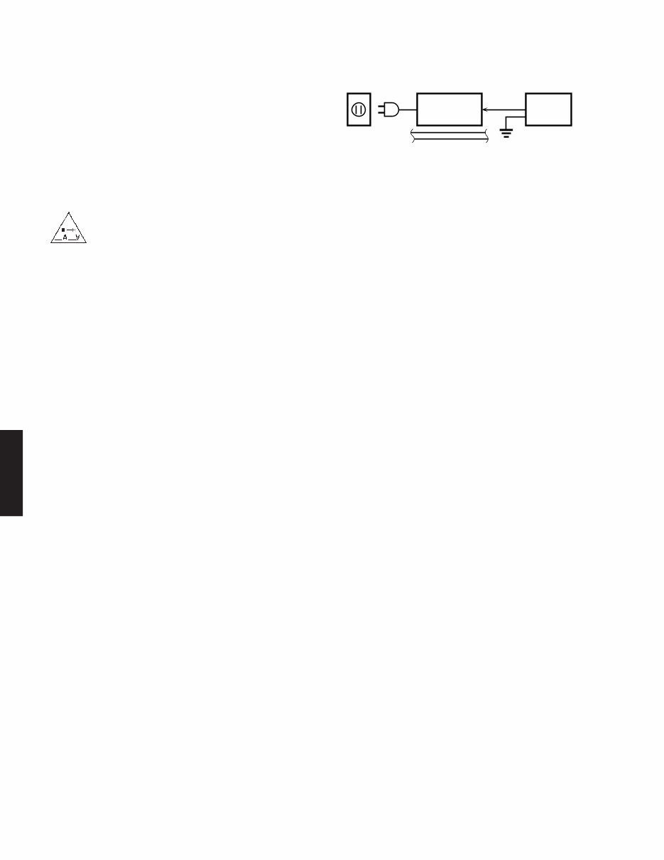
YSP-1100 2 YSP-1100 WARNING: CHEMICAL CONTENT NOTICE! The solder used in the production of this product contains LEAD. In addition, other electrical/electronic and/or plastic (where applicable) components may also contain traces of chemicals found by the California Health and Welfare Agency (and possibly other entities) to cause cancer and/or birth defects or other reproductive harm. DO NOT PLACE SOLDER, ELECTRICAL/ELECTRONIC OR PLASTIC COMPONENTS IN YOUR MOUTH FOR ANY REA- SON WHATSOEVER! Avoid prolonged, unprotected contact between solder and your skin! When soldering, do not inhale solder fumes or expose eyes to solder/flux vapor! If you come in contact with solder or components located inside the enclosure of this product, wash your hands before handling food. WALL OUTLET EQUIPMENT UNDER TEST AC LEAKAGE TESTER OR EQUIVALENT INSULATING TABLE ■ TO SERVICE PERSONNEL 1. Critical Components Information Components having special characteristics are marked s and must be replaced with parts having specifications equal to those originally installed. 2. Leakage Current Measurement (For 120V Models Only) When service has been completed, it is imperative to verify that all exposed conductive surfaces are properly insulated from supply circuits. ● Meter impedance should be equivalent to 1500 ohms shunted by 0.15µF. ● Leakage current must not exceed 0.5mA. ● Be sure to test for leakage with the AC plug in both polarities. “CAUTION” “F501: FOR CONTINUED PROTECTION AGAINST RISK OF FIRE, REPLACE ONLY WITH SAME TYPE 5A, 125V FUSE.” CAUTION F501: REPLACE WITH SAME TYPE 5A, 125V FUSE. ATTENTION F501: UTILISER UN FUSIBLE DE RECHANGE DE MEME TYPE DE 5A, 125V. 本機に搭載されているすべての基板は無鉛ハンダでハンダ 付けされています。 無鉛ハンダにはいくつかの種類がありますが、修理時には 下記のような無鉛ハンダの使用を推奨します。 ・Sn+Ag+Cu(錫+銀+銅) ・Sn+Cu(錫+銅) ・Sn+Zn+Bi (錫+亜鉛+ビスマス) 注意: 無鉛ハンダの融点温度は通常の鉛入りハンダに比べ30 ~40℃程度高くなっていますので、それぞれのハンダ に合ったハンダごてをご使用ください。 All of the P.C.B.s installed in this unit are soldered using the lead free solder. Among some types of lead free solder currently available, it is recommended to use one of the following types for the repair work. • Sn + Ag + Cu (tin + silver + copper) • Sn + Cu (tin + copper) • Sn + Zn + Bi (tin + zinc + bismuth) Caution: As the melting point temperature of the lead free solder is about 30°C to 40°C (50°F to 70°F) higher than that of the lead solder, be sure to use a soldering iron suitable to each solder. About Lead Free Solder / 無鉛ハンダについて
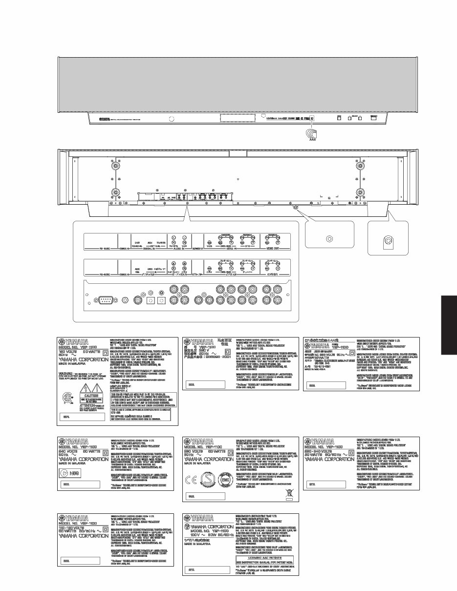
YSP-1100 3 YSP-1100 ■ FRONT PANEL ■ REAR PANELS J model (IR OUT) OPTIMIZER MIC U, C, T, K, A, B, G, E, L, V models J model BOTTOM VIEW U, C models T model K model A model B, G, E models V model J model L model
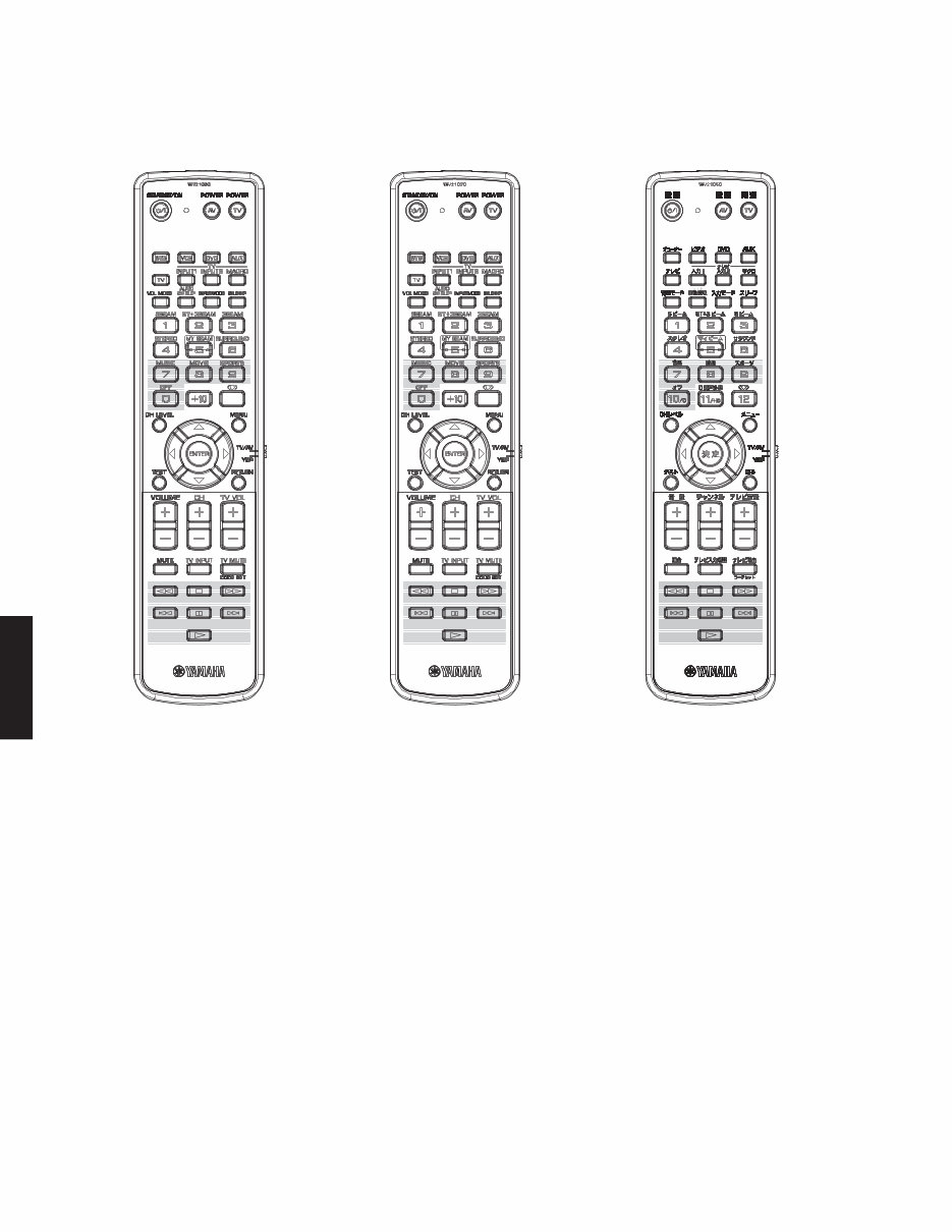
YSP-1100 4 YSP-1100 ■ REMOTE CONTROL PANELS U model C, T, K, A, B, G, E, L, V models J model
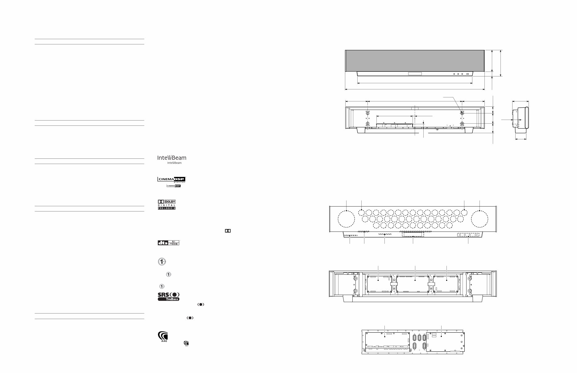
YSP-1100 5 ■ INTERNAL VIEW • DIMENSIONS / 寸法図 ■ SPECIFICATIONS / 参考仕様 6 3 4 5 7 1 DRIVER, WOOFER 2 DRIVER, TWEETER 3 OPERATION (3) P.C.B. 4 OPERATION (4) P.C.B. 5 INPUT (3) P.C.B. 6 OPERATION (1) P.C.B. 7 OPERATION (2) P.C.B. 8 AMP (2) P.C.B. 9 DSP P.C.B. 0 AMP (1) P.C.B. AINPUT (2) P.C.B. BINPUT (1) P.C.B. Front view Rear view Shield unit 2 2 1 1 8 9 A B 0 ■ Amplifier Section / アンプ部 Maximum Power / 実用最大出力 (EIAJ) Woofer [3 ohms, 100 Hz, 10% THD] ................................ 20 W/ch Tweeter [4 ohms, 1 kHz, 10% THD] ................................... 2 W/ch Total Maximum Output Power / 総合最大出力 ........................................................................................... 120 W Minimum RMS Output Power / 定格出力 Woofer [3 ohms, 100 Hz, 0.9% THD] ............................... 14 W/ch Tweeter [4 ohms, 1 kHz, 0.9% THD] ............................... 1.7 W/ch Input Sensitivity/Impedance / 入力感度/インピーダンス Analog input ....................................................... 1.0 V / 32 k-ohms Maximum Input Signal / 最大許容入力 [1 kHz, 0.5% THD] Analog input .............................................................. 2.2 V or more Output Level/Impedance / 出力電圧/出力インピーダンス Woofer PRE OUT ............... 1.5 V / 1.1 k-ohms (less than 120 Hz) Total Harmonic Distortion / 全高調波歪率 [1 W] Woofer [100 Hz] .......................................................... 0.2% or less Tweeter [1 kHz] ........................................................... 0.1% or less ■ Video Section / ビデオ部 Output Level Composite video .................................................... 1 Vp-p/75 ohms Component video Y ............................................. 1 Vp-p/75 ohms Pb, Pr .................................. 0.5 Vp-p/75 ohms Frequency Characteristics Composite video ........................................................ 5 Hz-10 MHz Component video ...................................................... 5 Hz-60 MHz ■ Speaker Section / スピーカー部 Type / 型式 ............................................... 2-way acoustic suspension Magnetic shielding type Drivers / スピーカーユニット Woofer ............................................. 11 cm (4-5/16") cone type x 2 Tweeter ............................................ 4 cm (1-9/16") cone type x 40 Frequency Response / 再生周波数帯域 ................. 55 Hz to 20 kHz Crossover Frequency / クロスオーバー周波数 Beam channel ...................................................................... 350 Hz Stereo channel ....................................................................... 1 kHz ■ Input/Output / 入力/出力 Input Jack / 入力端子 Audio ......................... VCR, TV/STB / ビデオ、テレビ/チューナー Digital (optical) [Fs=32/44.1/48/64/88.2/96 kHz] ................................... TV/STB, AUX / テレビ/チューナー、DVD Digital (coaxial) [Fs=32/44.1/48/64/88.2/96 kHz] .................................................................................... DVD / AUX Video (composite) ....... TV/STB, VIDEO, AUX / テレビ/チューナー、DVD、ビデオ U, C, K, V, J models ........................................................... NTSC T, A, B, G, E, L models .......................................................... PAL Component video ................................... TV/STB, DVD / テレビ/チューナー、DVD Output Jack / 出力端子 Video (composite) U, C, K, V, J models ........................................................... NTSC T, A, B, G, E, L models .......................................................... PAL Component video .............................................. Selected video out Subwoofer ....................................................................... PRE OUT Microphone Input Jack / マイク入力 ..................... Automated system calibration / 自動システム調整 Rmote Input/Output / リモート入力/出力 Input ................................................................................ Remote in RS-232C Output ........................................................... IR out (pass through) ■ General / 総合 Power Supply / 電源電圧 U, C models .......................................................... AC 120 V, 60 Hz T model ................................................................. AC 220 V, 50 Hz K model ................................................................. AC 220 V, 60 Hz A model ................................................................. AC 240 V, 50 Hz B, G, E models ..................................................... AC 230 V, 50 Hz L model .................................................... AC 220-240 V, 50/60 Hz V model .................................................... AC 110-120 V, 50/60 Hz J model ............................................................ AC 100V, 50/60 Hz Power Consumption / 消費電力 .............................................. 50 W Standby Power Consumption (Reference Data) / 待機時消費電力(参考値) ................................................................................ 0.1 W or less Dimensions / 寸法 (W x H x D) ...................... 1030 x 194 x 118 mm (40-9/16" x 7-5/8" x 4-5/8") Weight / 質量 ................................................ 13.0 kg (28 lbs. 10 oz.) Finish / 仕上げ Silver color ........................... U, C, T, K, A, B, G, E, L, V, J models Black color ........................... U, C, T, K, A, B, G, E, L, V, J models Accessories / 付属品 Remote control x 1, Batteries (UM-3) x 2, Power cable x 1, Video pin cable x 1, Audio pin cable x 2, Digital audio pin cable x 1, Optical cable x 1, Cable clip x 1, Fastener x 4, Optimizer microphone x 1, Cardboard microphone stand x 1, DVD-ROM x 1 (J model) U .......... U.S.A. model C ...... Canadian model T .......... Chinese model K ...... Korean model A .......... Australian model B ...... British model G .......... European model E ...... South European model L ........... Singapore model V ...... Taiwan model J ........... Japanese model * Specifications are subject to change without notice due to product improvements. ※ 参考仕様および外観は予告なく変更されることがあります。 TruBass, SRS and the “ ” symbol are registered trademarks of SRS Labs, Inc. TruBass technology is incorporated under license from SRS Labs, Inc. TruBass、SRSと 記号はSRS Lab,Inc.の商標です。 TruBass技術はSRS Labs,Inc.からのライセンスに基づき製品化されて います。 AACロゴマーク はドルビーラボラトリーズの商標です。 The “ ” logo and “IntelliBeam” are trademarks of YAMAHA Corporation. 「インテリビーム」 「IntelliBeam」は、ヤマハ株式会社の登録商標です。 The “ ” logo and “Cinema DSP” are registered trademarks of YAMAHA Corporation. 「シネマDSP」「CINEMA DSP」は、ヤマハ株式会社の登録商標です。 Manufactured under license from Dolby Laboratories. “Dolby”, “Pro Logic”, and the double-D symbol are trademarks of Dolby Laboratories. ドルビーラボラトリーズからの実施権により製造されています。「ドル ビー」、「PRO LOGIC」およびダブルD記号 は、ドルビーラボラト リーズの商標です。 “DTS”, and “Neo:6” are trademarks of Digital Theater Systems, Inc. DTSおよびNeo:6はデジタルシアターシステムズの登録商標です。 Manufactured under license from 1 Ltd. Worldwide patents applied for. The ‘ ’ logo and ‘Digital Sound Projector™’ are trademarks of 1 Ltd. 世界に広く特許申請中の1Ltdからライセンスを受けています。 ‘ ’および、‘Digital Sound Projector TM ’は1Ltdの商標です。 118 (4-5/8") 194 (7-5/8") 1030 (40-9/16") Unit : mm (inch) 単位 : mm (インチ) 160 (6-5/16") 34 (1-5/16") 848 (33-3/8") 79 (3-1/8") 41 (1-5/8") 700 (27-9/16") 4-M6 267 (10-1/2") 17 (11/16") 22.5 (7/8") 70 (2-3/4") 48 (1-7/8") 76 (3") 165 (6-1/2") 165 (6-1/2")
YSP-1100 6 ■ SET MENU TABLE / セットメニュー TRBL (0.5 dB step -12.0 to 0 to +12.0 [dB]) BASS (0.5 dB step -12.0 to 0 to +12.0 [dB]) FRONT, SWFR 80, 100, 120 [Hz] -20 to 0 [dB] 0.3 to 15.0 [m] (0.1 step) 1.0 to 50.0 [ft] (0.5 step) SHELF, WALL [NORMAL], HI ECHO FLAT TO WALL, ANGLE TO WALL OR CORNER 0.0 to 3.0 [m] (0.1 step) 0.0 to 10.0 [ft] (0.5 step) 2.0 to 12.0 [m] (0.1 step) 6.5 to 40.0 [ft] (0.5 step) 2.0 to 12.0 [m] (0.1 step) 6.5 to 40.0 [ft] (0.5 step) 1.8 to 9.0 [m] (0.1 step) 6.0 to 30.0 [ft] (0.5 step) 0.6 to 11.4 [m] (0.1 step) 2.0 to 38.0 [ft] (0.5 step) H.ANGLE FL (1 deg. step -90 deg to 0 to +90 deg) H.ANGLE FR (1 deg. step -90 deg to 0 to +90 deg) H.ANGLE C (1 deg. step -90 deg to 0 to +90 deg) H.ANGLE SL (1 deg. step -90 deg to 0 to +90 deg) H.ANGLE SR (1 deg. step -90 deg to 0 to +90 deg) V.ANGLE.FL (1 deg. step -45 deg to 0 to +45 deg) V.ANGLE.FR (1 deg. step -45 deg to 0 to +45 deg) V.ANGLE.C (1 deg. step -45 deg to 0 to +45 deg) V.ANGLE.SL (1 deg. step -45 deg to 0 to +45 deg) V.ANGLE.SR (1 deg. step -45 deg to 0 to +45 deg) DIST FL (0.1 m step 0.3 to 24.0 [m]) (0.5 ft step 1.0 to 80.0 [ft]) DIST FR (0.1 m step 0.3 to 24.0 [m]) (0.5 ft step 1.0 to 80.0 [ft]) DIST C (0.1 m step 0.3 to 24.0 [m]) (0.5 ft step 1.0 to 80.0 [ft]) DIST SL (0.1 m step 0.3 to 24.0 [m]) (0.5 ft step 1.0 to 80.0 [ft]) DIST SR (0.1 m step 0.3 to 24.0 [m]) (0.5 ft step 1.0 to 80.0 [ft]) F.L. FL (0.1 m step -1.0 to 13.0 [m]) (0.5 ft step -3.5 to 43.5 [ft]) F.L. FR (0.1 m step -1.0 to 13.0 [m]) (0.5 ft step -3.5 to 43.5 [ft]) F.L. C (0.1 m step -1.0 to 13.0 [m]) (0.5 ft step -3.5 to 43.5 [ft]) F.L. SL (0.1 m step -1.0 to 13.0 [m]) (0.5 ft step -3.5 to 43.5 [ft]) F.L. SR (0.1 m step -1.0 to 13.0 [m]) (0.5 ft step -3.5 to 43.5 [ft]) TRBL FL (0.5 dB step -12.0 to 0 to +12.0 [dB]) TRBL FR (0.5 dB step -12.0 to 0 to +12.0 [dB]) TRBL C (0.5 dB step -12.0 to 0 to +12.0 [dB]) TRBL SL (0.5 dB step -12.0 to 0 to +12.0 [dB]) TRBL SR (0.5 dB step -12.0 to 0 to +12.0 [dB]) L | · · · · · · · · C 0 to 95 [%] (5% step) (* 5) C · · · · · · · · | R 0 to 95 [%] (5% step) (* 5) [TV], VIDEO DVD, [AUX] U, C, T, K, A, B, G, E, L, V models [DVD], AUX J model [DVD], AUX U, C, T, K, A, B, G, E, L, V models DVD, [AUX] J model TV, [VCR] U, C, T, K, A, B, G, E, L, V models [TV], VCR J model DVD, [AUX] U, C, T, K, A, B, G, E, L, V models [DVD], AUX J model DVD, [AUX] U, C, T, K, A, B, G, E, L, V models [DVD], AUX J model · · · · | · · · · (0.5 dB step -6.0 to 0.0 [dB]) · · · · | · · · · (0.5 dB step -6.0 to 0.0 [dB]) · · · · | · · · · (0.5 dB step -6.0 to 0.0 [dB]) · · · · | · · · · (0.5 dB step -6.0 to 0.0 [dB]) · · · · | · · · · (0.5 dB step -6.0 to 0.0 [dB]) (* 12) A-Z, a-z, 0-9 -2, -1, OFF DISPLAY OFF, -3, -2, -1, OFF -5 to 0 to +5 (1 step) BLUE, GRAY 1 2 3 4 5 MEMORY AUTO SETUP MANUAL SETUP LANGUAGE SET (* 11) 1) LOAD 2) SAVE 1) BEAM+SOUND OPTIMZ 2) BEAM OPTIMZ ONLY 3) SOUND OPTIMZ ONLY 1) SOUND MENU 2) BEAM MENU 3) INPUT MENU 4) DISPLAY MENU A) TONE CONTROL B) SUBWOOFER SET C) MUTE LEVEL D) AUDIO DELAY E) ROOM EQ F) DD/DTS DYNAMIC RANGE A) SETTING PARAMETERS B) BEAM ADJ C) IMAGE LOCATION A) INPUT ASSIGNMENT (* 10) B) INPUT MODE C) INPUT TRIM D) INPUT RENAME (* 11) A) DIMMER SET B) OSD SET C) UNIT SET CATEGORY 1 MAIN MENU 2 SUB MENU 3 TREBLE BASS BASS OUT CROSS OVER LFE LEVEL DISTANCE MUTE, -20 dB 0 to 160 mS MOUNTING REFLECTING MIN, STD, MAX INSTALLED POSITION INSTALLED HEIGHT ROOM WIDTH (C: LEFT WALL) ROOM LENGTH (C: RIGHT WALL) USER POSITION TO L WALL (* 4) a) HORIZONTAL ANGLE (* 5) b) VERTICAL ANGLE (* 5) c) BEAM TRAVEL LENGTH d) FOCAL LENGTH (* 5) e) TREBLE GAIN ON, OFF LEFT RIGHT OPTICAL IN (1) OPTICAL IN (2) COAXIAL IN COMPONENT IN (1) COMPONENT IN (2) COMPOSITE IN AUTO, LAST OPTICAL IN (1)TV ANALOG OPTICAL IN (2) OPTICAL COAXIAL IN VCR ANALOG ANALOG IN (1) AUX OPTICAL ANALOG IN (2) DVD COAXIAL DVD - > _ DVD STANDARD DIMMER AUTO DIMMER OSD SHIFT OSD BACK COLOR SELECT MENU 4 VALUE [INITIAL] ENGLISH, DEUTSCH, Francais, ESPANOL *4 ..... Displayed only for the FLAT TO WALL setting; distance from the wall on the left side to the user. / 壁置き設定のみ表示。左壁からユーザーまでの距離。 *5 ..... Test tone output. / テストトーン出力。 *10 ... Priority given to COAXIAL when set to the same input. / 同じ入力に設定した場合は、COAXIAL優先。 *11... Displayed only for the U, C, T, K, A, B, G, E, L, V models. *12 ... MAX 8 Character. / 最大8文字。 MEMORY 1, MEMORY 2, MEMORY 3 MEMORY 1, MEMORY 2, MEMORY 3 METERS, FEET (U, C, T, K, A, B, G, E, L, V models)
YSP-1100 7 YSP-1100 (番号順に部品を取り外してください。) 分解・組立時の注意: ・ AC電源コンセントから、電源コードを抜いてください。 ・ やわらかい布等を敷いて その上で作業を行ってください。 ・ フロントグリル等で怪我をする恐れがあります。十分 注意してください。 ・ ネジを閉め忘れると、エアー漏れをすることがあります。 ネジの個数及び位置を確認し、取り付けてください。 ・ 取り付けの際、ケーブル等を部品の隙間に挟み込むこ とがあります。十分注意してください。 ・取り外したスピーカーユニット(ツイーター)はすべて 決められた位置に取り付けてください。 ■ DISASSEMBLY PROCEDURES / 分解手順 (Remove parts in the order as numbered.) Cautions for disassembly and reassembly : • Disconnect the power cable from the AC outlet. • Spread soft cloth or the like and perform the work on it. • Use full care as you may be injured by the front grille or other part. • All screws must be tightened securely to prevent air leakage. Check the number of screws and their positions when installing them. • When installing parts, be careful not to have anything such as cables caught between other parts. • Make sure that all the removed driver (tweeter) parts are reinstalled at specified positions. ■ SERVICE PRECAUTIONS / サービス時の注意事項 安全対策 ・ この製品の内部には高電圧部分があり危険です。修理の 際は、絶縁性の手袋を使用するなどの安全対策を行って ください。 ・ INPUT(1)P.C.B.のC523には電源をOFFにした後も電 荷が残り、高電圧が維持されており危険です。 修理作業前に放電用抵抗(5 kΩ/10 W)をC523の端子間 に接続して放電してください。 (放電用抵抗の接続箇所はP.52“PRINTED CIRCUIT BOARD[INPUT(1)P.C.B.]”およびP.67“SCHEMATIC DIAGRAM[INPUT 2/2]”に記載しています。) Safety measures • Some internal parts in this product contain high voltages and are dangerous. Be sure to take safety measures during servicing, such as wearing insulating gloves. • Note that C523 on the INPUT (1) P.C.B. is dangerous even after the power is turned off because an electric charge remains and a high voltage continues to exist there. Before starting any repair work, perform discharge by connecting a discharge resistor (5 k-ohms/10 W) between C523 terminals. (For the discharge resistor connection points, refer to page 52 “PRINTED CIRCUIT BOARD [INPUT (1) P.C.B.]” and page 67 “SCHEMATIC DIAGRAM [INPUT 2/2]”)
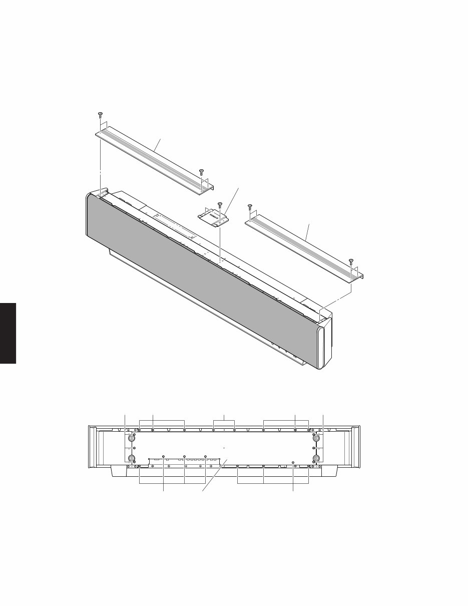
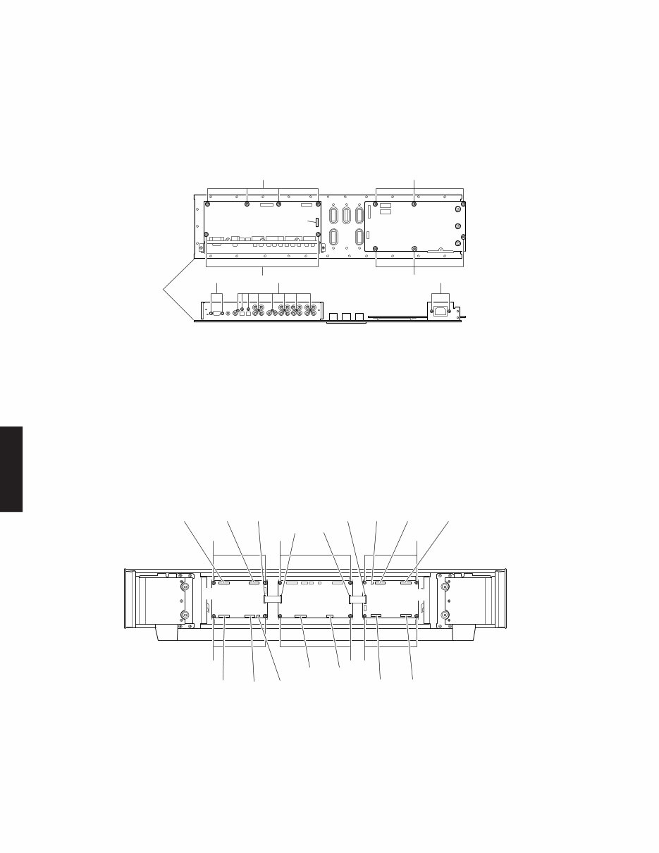
YSP-1100 8 YSP-1100 Fig. 2 3 3 3 3 3 3 3 Rear panel リアパネル 1. Removal of Top Panels and Plate/Top a. Remove 8 screws (1). (Fig. 1) b. Remove 2 top panels. c. Remove 2 screws (2). (Fig. 1) d. Remove the plate/top. 1 1 1 1 2 Top panel トップパネル� Top panel トップパネル� Plate/ top プレート/トップ� Fig. 1 1. トップパネル、プレート/トップの外し方 a. ①のネジ 8本を外します。(Fig. 1) b. トップパネル 2個を取り外します。 c. ②のネジ 2本を外します。(Fig. 1) d. プレート/トップを取り外します。
YSP-1100 9 YSP-1100 2. Removal of Shield Unit a. Remove 22 screws (3). (Fig. 2) b. Remove the rear panel. c. Remove 18 screws (4). (Fig. 3) d. Remove CB2, CB3, CB4, CB504, CB507 and CB508. (Fig. 3) e. Remove 5 pad LNs. f. Remove the shield unit. 2. シールドユニットの外し方 a. 3のネジ 22本を外します。(Fig. 2) b. リアパネルを取り外します。 c. 4のネジ 18本を外します。(Fig. 3) b. コネクター CB2~4、CB504、CB507、CB508を外し ます。(Fig. 3) e. パッド LN 5個を取り外します。 f. シールドユニットを取り外します。 Fig. A Fig. 3 When checking the P.C.B. : • The shield unit removed from the unit does not work because its grounding is loose. Be sure to connect the ground of the shield unit to the chassis or GND with a ground lead or the like. (Fig. A) • Reconnect all cables (connectors) that have been disconnected. • When connecting the cable, use care for the polarity. P.C.B.チェックをする場合には ・ 取り外したシールドユニットはアースが浮いて動作し ませんので、リード線等でシャーシ、またはGNDに接 続してください。(Fig. A) ・外したケーブル(コネクター)をすべて接続します。 ・ ケーブルを接続する際、極性に注意してください。 CB3 CB2 CB508 CB504 CB507 CB4 Shield unit シールドユニット� Pad LN パッドLN 4 4 4 4 4 4 Shield unit シールドユニット� Front panel unit フロントパネルユニット� DSP P.C.B. AMP (R) P.C.B. AMP (L) P.C.B. Ground lead アース線�
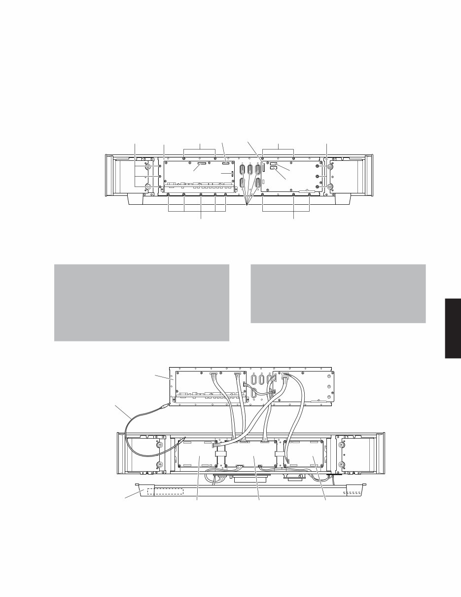
YSP-1100 10 YSP-1100 Fig. 4 Fig. 5 3.INPUT(1)、(2)P.C.B.の外し方 a. 5のネジ 6本、6のネジ 8本、7のジャックスクリュー 2本を外します。(Fig. 4) b. コネクター CB4を外します。(Fig. 4) c.INPUT(2)P.C.B.を取り外します。 d. 8のネジ 6本、9のネジ 2本を外します。(Fig. 4) e.INPUT(1)P.C.B.を取り外します。 3. Removal of INPUT (1) and (2) P.C.B.s a. Remove 6 screws ( 5), 8 screws (6) and 2 jack screws ( 7). (Fig. 4) b. Remove CB4. (Fig. 4) c. Remove the INPUT (2) P.C.B.. d. Remove 6 screws (8) and 2 screws (9). (Fig. 4) e. Remove the INPUT (1) P.C.B.. 4.DSP P.C.B.、AMP(L)、(R)P.C.B.の外し方 a. 0のネジ 4本を外します。(Fig. 5) b. コネクター CB6~9を外します。(Fig. 5) c. DSP P.C.B.を取り外します。 d. Aのネジ 8本を外します。(Fig. 5) e. コネクター CB507、CB509~512、CB707、CB709~712 を外します。(Fig. 5) f. AMP(L)、(R)P.C.B.を取り外します。 4. Removal of DSP P.C.B., AMP (L) and (R) P.C.B.s a. Remove 4 screws (0). (Fig. 5) b. Remove CB6, CB7, CB8 and CB9. (Fig. 5) c. Remove DSP P.C.B.. d. Remove 8 screws (A). (Fig. 5) e. Remove CB507, CB509, CB510, CB511, CB512, CB707, CB709, CB710, CB711 and CB712. (Fig. 5) f. Remove the AMP (L) and (R) P.C.B.s. CB4 Shield unit シールドユニット� 8 5 7 6 8 9 5 INPUT (1) P.C.B. INPUT (2) P.C.B. 0 0 CB510 CB7 CB6 CB709 CB710 CB512 CB511 CB507 A A A A CB509 CB502 CB8 CB9 CB707 CB702 CB712 CB711 DSP P.C.B. AMP (L) P.C.B. AMP (R) P.C.B. R ch L ch
Is your Yamaha YSP-1100 Sound Projector causing you trouble? Don't spend a fortune on repairs or replacements when you can take matters into your own hands!
This comprehensive service and repair manual is utilized by certified Yamaha technicians and is designed to assist you in troubleshooting and fixing your sound projector.
Contents:
FRONT PANEL
REAR PANELS
REMOTE CONTROL PANELS
SPECIFICATIONS
INTERNAL VIEW
SET MENU TABLE
SERVICE PRECAUTIONS
DISASSEMBLY PROCEDURES
UPDATING FIRMWARE
SELF DIAGNOSIS FUNCTION
DISPLAY DATA
IC DATA
BLOCK DIAGRAM
PRINTED CIRCUIT BOARD
PIN CONNECTION DIAGRAM
SCHEMATIC DIAGRAM
PARTS LIST
REMOTE CONTROL
ADJUSTING SYSTEM PARAMETERS
This service manual is incredibly detailed, featuring images and step-by-step instructions to ensure you can effectively repair and service your device.
Rest assured, this is the official service and repair manual in PDF format, ensuring high resolution for quality printing of the necessary pages.
Gain instant access upon payment, eliminating shipping fees and waiting time. You can commence your repairs immediately!
Specifications:
Language: English & Japanese
Format: PDF
Pages: 98
Platform: Windows and MAC
If you're in search of a specific service manual, feel free to reach out to us with your request. With one of the most extensive service manual databases available, we're likely able to assist you!