

LG HLS26W Speaker Sound Bar Service Manual
What's Included?
Fast Download Speeds
Online & Offline Access
Access PDF Contents & Bookmarks
Full Search Facility
Print one or all pages of your manual
P/NO : AFN74972282 APRIL, 2011
Speaker Sound Bar
SERVICE MANUAL
MODEL: HLS26W
CAUTION
BEFORE SERVICING THE UNIT, READ THE “SAFETY PRECAUTIONS”
IN THIS MANUAL.
Website http://biz.lgservice.com
Internal Use Only
MODEL: HLS26W SERVICE MANUAL

1-1
CONTENTS
SECTION 1 ........ GENERAL
SECTION 2 ........ CABINET & MAIN CHASSIS
SECTION 3 ........ ELECTRICAL
SECTION 4 ........ REPLACEMENT PARTS LIST

1-2
SECTION 1
GENERAL
CONTENTS
ESD PRECAUTIONS ....................................................................................................................................... 1-3
PROGRAM DOWNLOAD & UPGRADE GUIDE ........................................................................................... 1-4
SPECIFICATIONS ............................................................................................................................................ 1-5
1-3
ESD PRECAUTIONS
Electrostatically Sensitive Devices (ESD)
Some semiconductor (solid state) devices can be damaged easily by static electricity. Such components
commonly are called Electrostatically Sensitive Devices (ESD). Examples of typical ESD devices are integrated
circuits and some field-effect transistors and semiconductor chip components. The following techniques should
be used to help reduce the incidence of component damage caused by static electricity.
1. Immediately before handling any semiconductor component or semiconductor-equipped assembly, drain off
any electrostatic charge on your body by touching a known earth ground. Alternatively, obtain and wear a
commercially available discharging wrist strap device, which should be removed for potential shock reasons
prior to applying power to the unit under test.
2. After removing an electrical assembly equipped with ESD devices, place the assembly on a conductive surface
such as aluminum foil, to prevent electrostatic charge buildup or exposure of the assembly.
3. Use only a grounded-tip soldering iron to solder or unsolder ESD devices.
4. Use only an anti-static solder removal device. Some solder removal devices not classified as "anti-static" can
generate electrical charges sufficient to damage ESD devices.
5. Do not use freon-propelled chemicals. These can generate electrical charges sufficient to damage ESD
devices.
6. Do not remove a replacement ESD device from its protective package until immediately before you are
ready to install it. (Most replacement ESD devices are packaged with leads electrically shorted together by
conductive foam, aluminum foil or comparable conductive materials).
7. Immediately before removing the protective material from the leads of a replacement ESD device, touch the
protective material to the chassis or circuit assembly into which the device will by installed.
CAUTION : BE SURE NO POWER IS APPLIED TO THE CHASSIS OR CIRCUIT, AND OBSERVE ALL OTHER
SAFETY PRECAUTIONS.
8. Minimize bodily motions when handing unpackaged replacement ESD devices. (Otherwise harmless motion
such as the brushing together of your clothes fabric or the lifting of your foot from a carpeted floor can generate
static electricity sufficient to damage an ESD device).
CAUTION. GRAPHIC SYMBOLS
THE LIGHTNING FLASH WITH APROWHEAD SYMBOL. WITHIN AN EQUILATERAL TRIANGLE, IS
INTENDED TO ALERT THE SERVICE PERSONNEL TO THE PRESENCE OF UNINSULATED
“DANGEROUS VOLTAGE” THAT MAY BE OF SUFFICIENT MAGNITUDE TO CONSTITUTE A RISK OF
ELECTRIC SHOCK.
THE EXCLAMATION POINT WITHIN AN EQUILATERAL TRIANGLE IS INTENDED TO ALERT THE
SERVICE PERSONNEL TO THE PRESENCE OF IMPORTANT SAFETY INFORMATION IN SERVICE
LITERATURE.

1-4
PROGRAM DOWNLOAD & UPGRADE GUIDE
1. AUDIO MICOM
BOOTING FUNCTION DISPLAY USB FUNCTION Insert USB “MICOM UP” DISPLAY
After update, the set is turned off automatically.
2. DSP
BOOTING FUNCTION DISPLAY USB FUNCTION Insert USB “DSP UP” DISPLAY
After update, the set is turned off automatically.
3. MCS
BOOTING FUNCTION DISPLAY USB FUNCTION Insert USB “MCS UP” DISPLAY
After update, “FINISHED” DISPLAY.
• FACTORY RESET:
SET “STOP KEY” + REMOTE CONTROL “2”
• AUDIO MICOM OPTION CODE SETTING (SERVICE INFORMATION FOR EEPROM)
SET “STOP KEY” + REMOTE CONTROL “2” Change the value of Option Code with arrow key
REMOTE CONTROL “STOP KEY” SET(STOP KEY) + REMOTE CONTROL “2” Complete.

1-5
SPECIFICATIONS
• GENERAL
Power requirements Refer to main label.
Power consumption Refer to main label.
Dimensions (W x H x D) (39 x 3 x 20) inches without foot
Net Weight (Approx.) 5.1 lbs
Operating temperature 41 °F to 95 °F (5 °C to 35 °C)
Operating humidity 5 % to 90 %
Bus Power Supply (USB) DC 5 V 500 mA
• INPUTS
DIGITAL IN (OPTICAL IN) 3 V (p-p), Optical jack x 2
PORT. IN 0.5Vrms (3.5 mm stereo jack)
• AMPLIFIER
Stereo mode 70 W + 70 W (4 Ω at 1 kHz)

1-6
MEMO

2-1
SECTION 2
CABINET & MAIN CHASSIS
CONTENTS
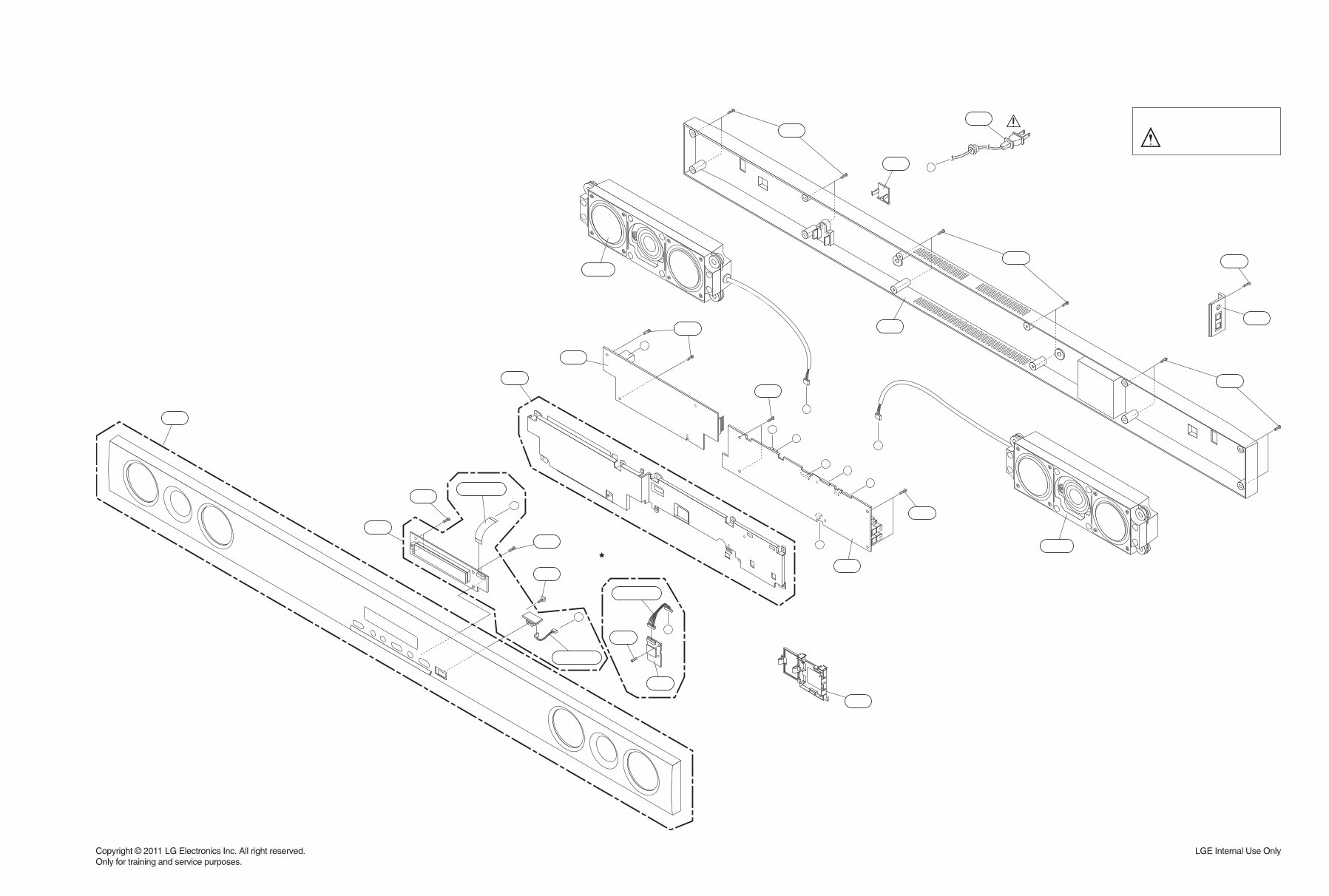
EXPLODED VIEWS ......................................................................................................................................... 2-3
1. RECEIVER BAR SECTION (HLS36W) .................................................................................................... 2-3
2. PACKING ACCESSORY SECTION ......................................................................................................... 2-7

2-2
MEMO
C
F
B
G
G
A
F
D
A
B
C
D
E
300
463
463
480
452
452
452
464
A42
A43
A53
465
253
255
A47
260
261
263
A46
454
454
454
256R
256L
CABLE1
CABLE2
CABLE3
SMPS
FRONT
USB
BLUETOOTH
OPTION
MAIN
2-4 2-3
EXPLODED VIEWS
1. RECEIVER BAR SECTION (HLS26W)
NOTES) THE EXCLAMATION POINT WITHIN AN
EQUILATERAL TRIANGLE IS INTENDED
TO ALERT THE SERVICE PERSONNEL
TO THE PRESENCE OF IMPORTANT
SAFETY INFORMATION IN SERVICE
LITERATURE.
You're Reading a Preview
What's Included?
Fast Download Speeds
Online & Offline Access
Access PDF Contents & Bookmarks
Full Search Facility
Print one or all pages of your manual
$31.99
Viewed 36 Times Today


Secure transaction
What's Included?
Fast Download Speeds
Online & Offline Access
Access PDF Contents & Bookmarks
Full Search Facility
Print one or all pages of your manual
$31.99
The LG HLS26W Speaker Sound Bar Service Manual is a comprehensive guide for repairing and maintaining the LG HLS26W Speaker Sound Bar. This manual is available in English and comes in PDF format. It contains detailed technical information, diagrams, and instructions essential for troubleshooting and repairing the speaker sound bar.
Whether you are a professional mechanic or a DIY enthusiast, this manual provides valuable insights into the inner workings of the LG HLS26W Speaker Sound Bar, making it an indispensable resource for anyone looking to ensure optimal performance and longevity of the device.


