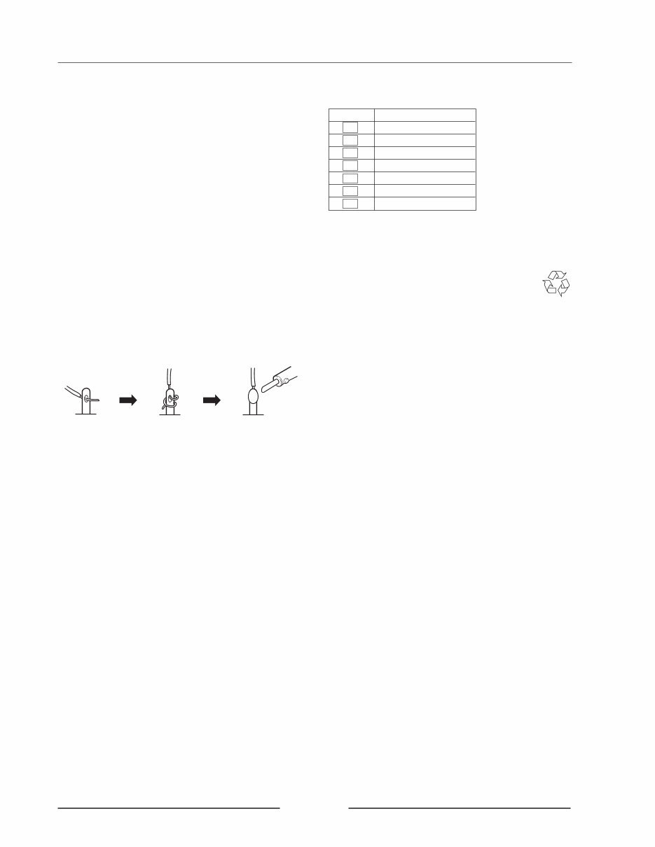
SERVICE MANUAL 2 # SAFETY INSTRUCTIONS # INFORMATIONS 1. Parts identified by the } symbol are critical for safety. Replace them only with the parts number specified. 2. In addition to safety, other parts and assemblies are specified for conformance with such regulations as those applying to spurious radiation. These must also be replaced only with the specified replacements. Examples : Noise blocking capacitors, noise blocking filters, etc. 3. Use specified internal wiring. Note especially : 1) Wires covered with PVC tubing 2) Double insulated wires 3) High voltage leads 4. Use specified insulating materials for hazardous live parts. Note especially : 1) Insulation Tape 2) PVC tubing 3) Spacers (insulating barriers) 4) Insulation sheets for transistors 5) Plastic screws for fixing micro switches 5. When replacing AC primary side components (trans- formers, power cords, noise blocking capacitors, etc.), wrap the ends of the wires securely around the terminals before soldering. 6. Make sure that wires do not contact heat producing parts (heat sinks, oxide metal film resistors, fusible resistors, etc.). 7. Check that replaced wires do not contact sharp edged or pointed parts. 8. Also check areas surrounding repaired locations. 9. Make sure that foreign objects (screws, solder droplets, etc.) do not remain inside the set. SAFETY CHECK AFTER SERVICING After servicing, make measurements of leakage-current or resistance in order to determine that exposed parts are acceptably insulated from the supply circuit. The leakage- current measurement should be done between accessible metal parts (such as chassis, ground terminal, microphone jacks, signal input/output connectors, etc.) and the earth ground through a resistor of 1500 ohms paralleled with a 0.15 μF capacitor, under the unit’s normal working conditions. The leakage-current should be less than 0.5 mA rms AC. The resistance measurement should be done between accessible exposed metal parts and power cord plug prongs with the power switch (if included) “ON”. The resistance should be more than 2.2 M ohms. SYMBOLS FOR PRIMARY DESTINATION Unit destinations are indicated with letters as shown below. Symbols Principal Destinations A U.S.A B England E Europe J Japan V Germany X1 Japan X4 Universal Area MAKE YOUR CONTRIBUTION TO PROTECT THE ENVIRONMENT Used batteries with the ISO symbol for recycling as well as small accumulators (rechargeable batteries), mini-batteries (cells) and starter batteries should not be thrown into the garbage can. Please leave them at an appropriate depot. PRECAUTIONS FOR LITHIUM BATTERY The lithium battery may explode when incorrectly replaced. [OBSERVE THE FOLLOEING WHEN REPLACING] • Replace with the same make and type or equivalent recom mended by manufacturer. • Place battery in correct polarity. • Do not short the terminals. • Do not charge battery. • Do not dispose of battery in fire.
SERVICE MANUAL 3 General Power supply 100-240V AC 50/60Hz 70W (27W without options) Dimensions 526 (W) x 170 (H) x 453 (D) mm (with LCD tilted down) Weight 10.5kg (without options) Display 320 x 240 dots grey-scale graphical LCD w/back light Sound Generator Sampling rate 44.1kHz, 48kHz, 96kHz Data format 24/16 bit linear Sampling time 180/120 (16/24 bit) seconds mono FS=44.1kHz (unexpanded memory) 166/110 (16/24 bit) seconds mono FS=48kHz 82/53 (16/24 bit) seconds mono FS=96kHz 90/60 (16/24 bit) seconds stereo FS=44.1kHz 83/55 (16/24 bit) seconds stereo FS=48kHz 40/26 (16/24 bit) seconds stereo FS=96kHz Memory 16MB standard, expandable to 512MB 168-pin DIMM (PC133/PC100, CL2) slot x 2 Polyphony 64 voices Filter 2-pole x 3 with resonance Envelope generators 3 x Envelope generators (2 multi-stage) LFO 2 x Multi-wave Sequencer Maximum events 300,000 notes (equivalent) Resolution 960 parts per 1/4-note (ppq) Sequences 128 Tracks per sequence 128 MIDI output channels 64 (16 channels x 4 output ports) Song mode 128 songs, 250 steps per song Drum pads 16 (velocity and pressure sensitive) Drum pads banks 6 Sync modes MTC, MIDI clock, SMPTE Inputs/Outputs Rec In LINE/MIC L/R 1/4-inch stereo phone/XLR Combo jack, balanced, 1/4-inch phone, Imp. 18kΩ, 24dBu max./XLR, Imp. 6kΩ, 22dBu max. Rec In PHONO L/R RCA phono x 2 with RIAA EQ, -24dBu max. (1kHz) Main Out L/R 1/4-inch stereo phone/XLR Combo jack, balanced, 1/4-inch phone, Imp. 1.7kΩ, 24dBu max./XLR, Imp. 200Ω, 18dBu max. Assignable Outs (IB-48P required) 1/4-inch stereo phone x 8, balanced, Imp. 1.7kΩ, 18dBu max. Headphone 1/4-inch stereo phone, 60mW (32Ω) Digital Input (IB-4D required) RCA phono x 1, SPDIF Digital Main Output (IB-4D required) RCA phono x 1, SPDIF Word Clock Input (IB-4D required) BNC x 1 (w/75Ω terminator On/Off) SMPTE In 1/4-inch stereo phone, balanced SMPTE Out 1/4-inch stereo phone, balanced Footswitch 1/4-inch phone x 2 MIDI Input 5-pin DIN x 2 MIDI Output 5-pin DIN x 4 SCSI 50-pin high-pitch SCSI connector x 1 USB Host x 1, Slave x 1 (V1.1) Options IB-4D Digital Audio (SPDIF) I/O board IB-4ADT Adat Interface board (2-in/8-out) IB-48P Assignable 8-channel Output Board Standard accessory Power Cable x 1 CD-ROM disc x 1 Drive Mounting Kit x 1 User Guide x 1 * The specifications are subject to change without the prior notice. I. SPECIFICATIONS
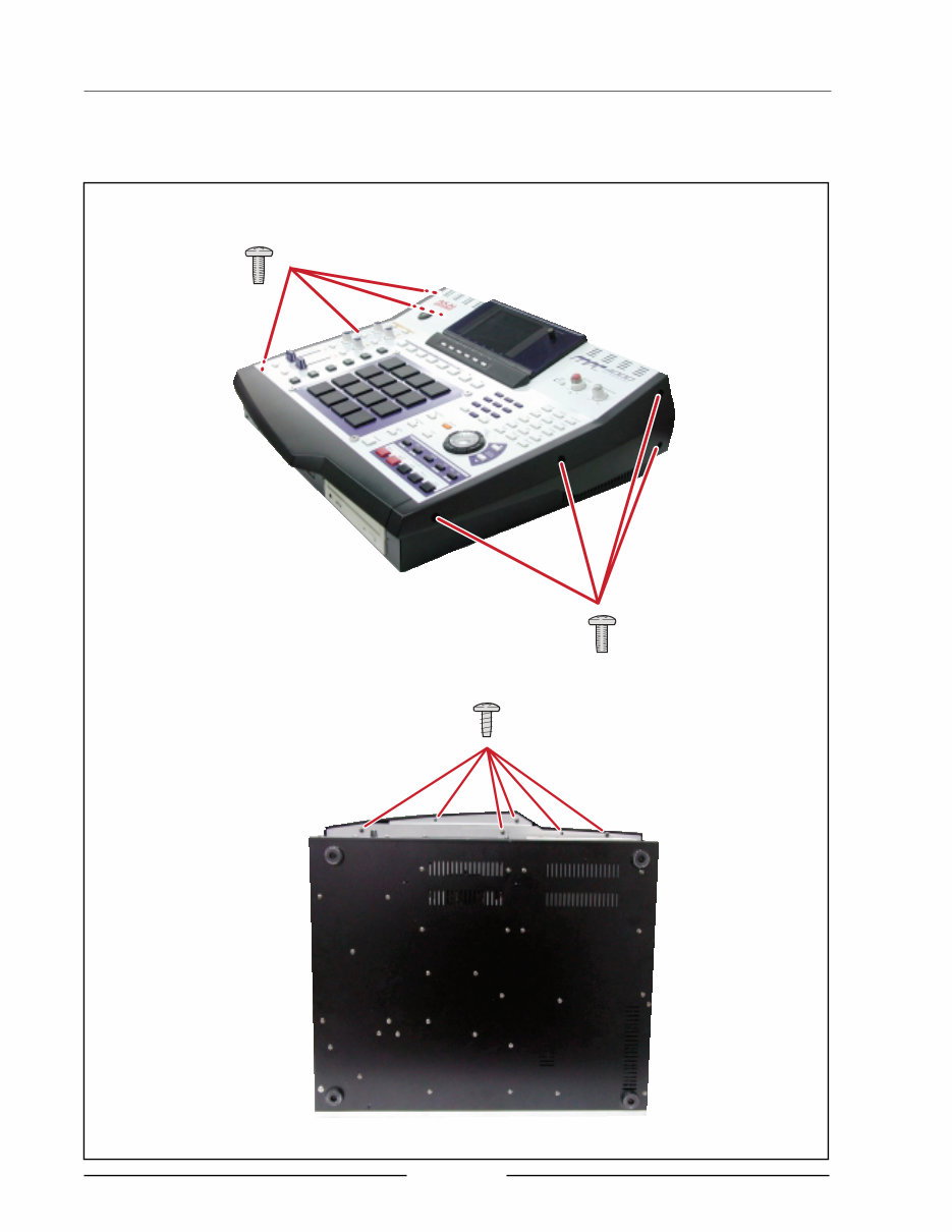
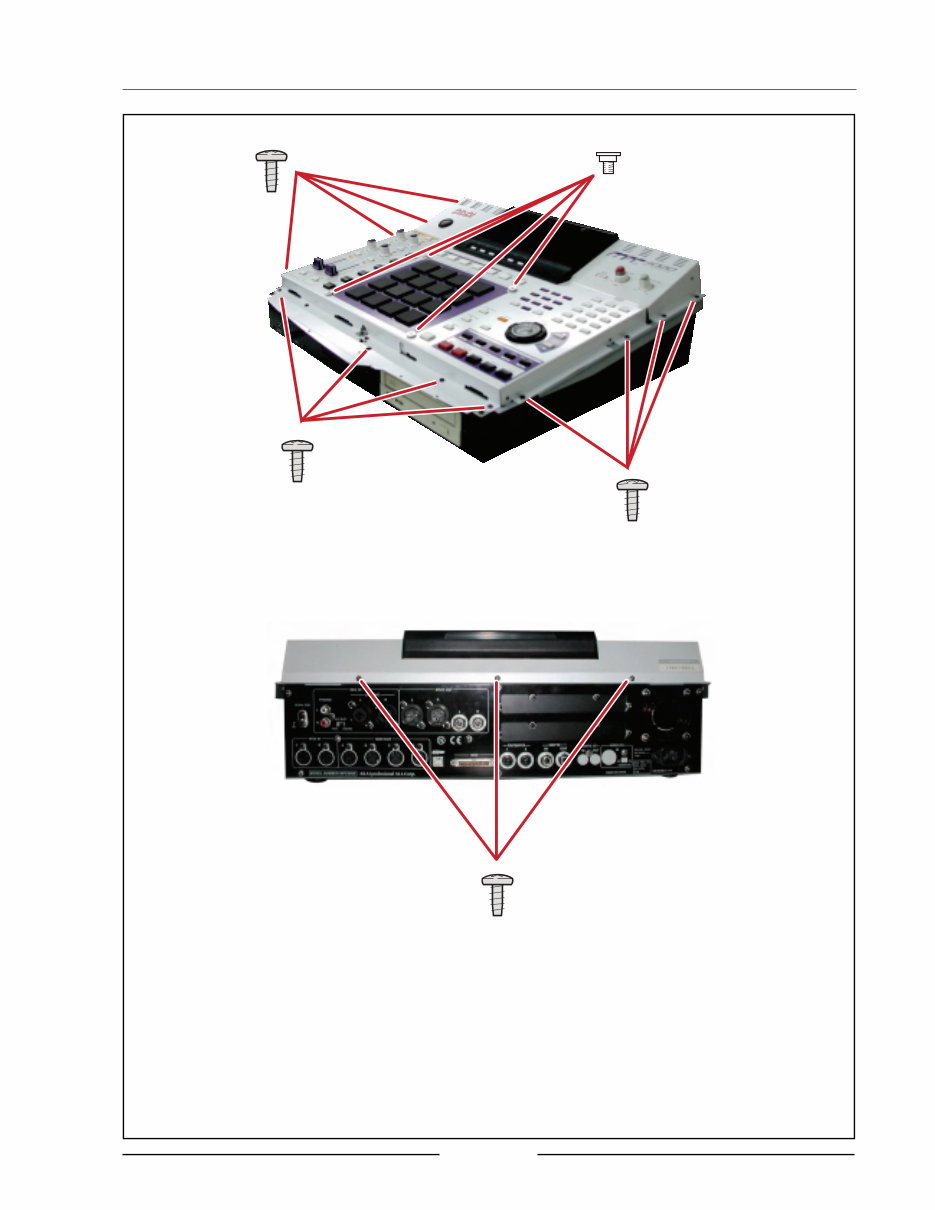
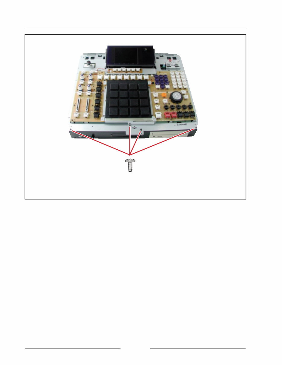
SERVICE MANUAL 4 II. DISASSEMBLY In case of trouble, etc., necessitating dismantling, please dismantle in the order shown in the illustrations. Reassemble in the reverse order. 1. Removal of the OPERATION BLOCK ZS-322570 ST BID40X08STL NI3 ZS-331182 BT BID30X08STL BNI
SERVICE MANUAL 5 ZS-331182 BT BID30X08 STL BNI ZS-331182 BT BID30X08 STL BNI ZS-821548X SCREW TOP COVER NI
SERVICE MANUAL 6 ZS-331182 BT BID30X08 STL BNI
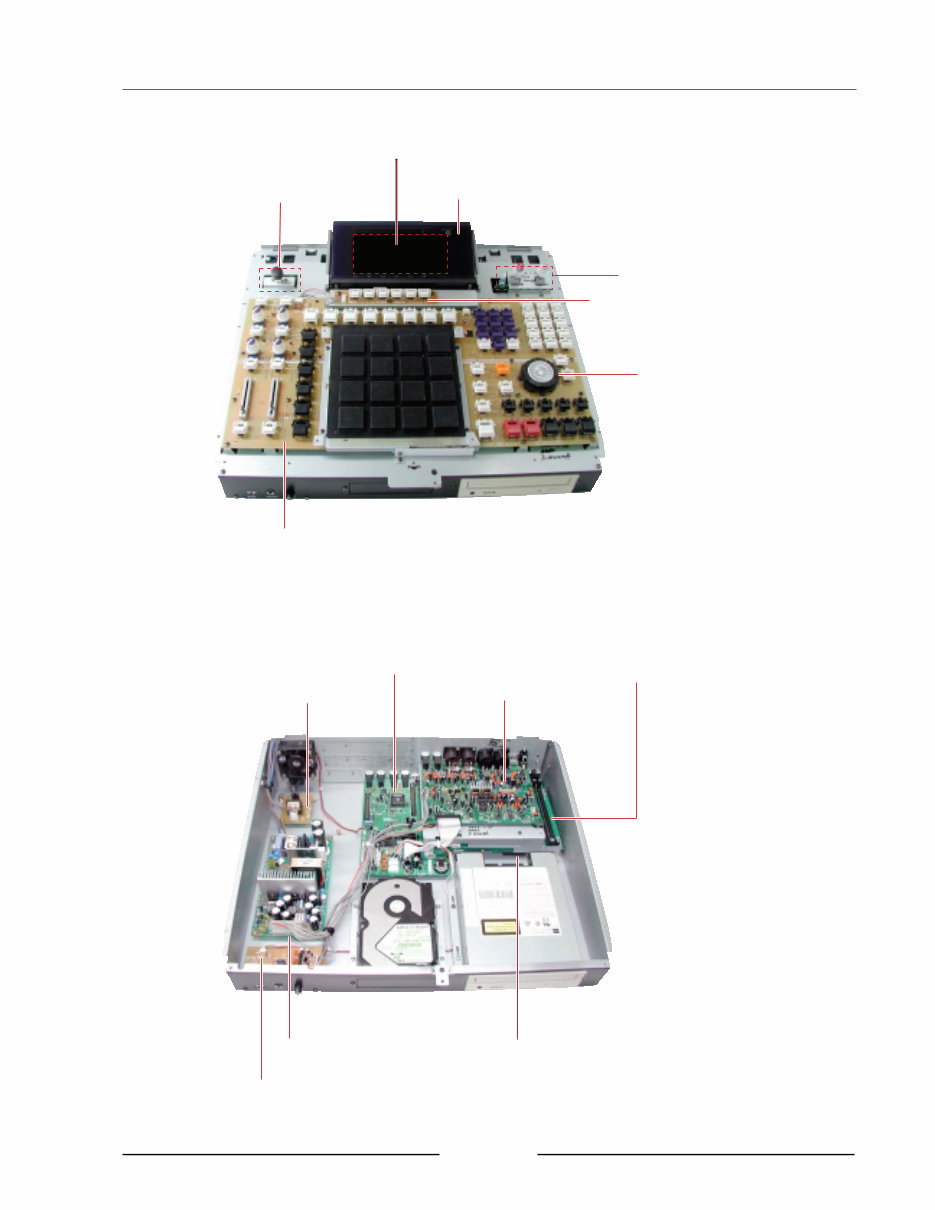
SERVICE MANUAL 7 PC JOG BLK PC FUNCTION BLK PC IO VR BLK PC OPERATION BLK PC POWER SW BLK PC LCD BLK BA-L4016A504F BA-L4016A504C EM-812761J IND LCD BA-L4016A502C BA-L4016A504B BA-L4016A504A BA-L4016A030A PC FILTER BLK PC IO BLK PC IO ADDA BLK PC CPU BLK Z8 PC HEAD PHONE & USB BLK EB4JS BA-L4016A504E BA-L4016A502A BA-L4016A502B BA-L6052A020A BA-L4016A504D BA-LJ038A020A PC POWER BLK SPS-80 III. PRINCIPAL PARTS LOCATION
SERVICE MANUAL 8 IV. OS Update Procedure OS Update Procedure [OS Update procedure from USB] The OS update can be made from the PC via the USB port. You must have the “OS loader software for MPC4000” besides the OS .bin file. The OS loader software includes the OS Loader.exe file, USB driver.inf file, and USB Driver.sys file. 1. Install USB Driver to your PC After all files are un-Zipped, place the USB Driver.inf and USB Driver.sys files into the same folder, e.g. Driver. Boot up the PC and MPC4000 complete and then connect the sampler to the PC using the USB cable. This prompts that the PC found the new device an d the new driver is required. Refer it to the Driver folder you just created. The Driver software will be placed correctly and the MPC4000 is recognized properly. 2. OS update Double click on the OS Loader.exe icon and specify the OS .bin file. It will send the OS to the MPC4000. [Caution] After the update, be sure to initialize the MPC4000 by pressing the GLOBAL key, and then [F6] (INITIAL) and [F5] (DO IT) keys, before turning it off. [OS update procedure from CD-R] To update the OS from the CD-ROM, it requires the OS version later than V1.02 software installed on the MPC4000. You can update the OS from the CD-ROM drive. Be sure to use the CD-ROM that contains the OS for the MPC 4000. You can create the OS disc by using your PC’ s CD-R/W function to write the “MPC4000.bin” file on to an ISO9660 CD-ROM disc. 1. Turn the MPC4000 on and insert the OS disc. 2. Press the LOAD key and select the MPC4000 OS file (.bin file). 3. Press the [F6] (DO IT) key and then the [F6] (INSTALL) key. 4. The OS Update progress appears, i.e. the messages “Please wait ??.” and then “Upgrading of the Flash ROM was successful.” appear accordingly. 5. Press the [F6] (Restart) key. Be sure to initialize the MPC4000 by pressing the GLOBAL key, and then the [F6] (INITIAL) and [F5] (DO IT) keys, before turning it off. Writing Panel OS Program Change the position of the Short Pin P15 on the IO PCB to PROG side. The OS is automatically written to the Panel CPU RAM when the MPC4000 is switched on. Switch the unit off when the “Process completed!” prompt message appeared and then replace the Short Pin to the original position.
SERVICE MANUAL 9 Panel Test Mode To enter the Panel Test Mode, press the GLOBAL key while holding down the SHIFT key in the GLOBAL page [F1] of the GLOBAL Mode. • Moving the Q-link knobs changes the graphics accordingly. • Tapping the PAD shows the amount of pressure applied on the bar graph. • Switching the FOOT Pedal on/off changes the graphics accordingly. • Turning the JOG wheel increases/decreases the value in the Data field. • Pressing the key shows its name at the bottom of the screen. For those keys with the LED, the LED is turned on/off. • Pressing the [F1] key stops the key test. • After stopping the key test, pressing the mode key will abort the test mode. • While the key test is stopped, pressing the SHIFT key and [F6] key shows the A/D converted value of the Q-link/ PAD. CPU Board Test Mode The Test Mode of the MPC4000 CPU Board is performed while the CPU board is mounted on the Z4/Z8 Sampler. When the Z4/Z8 is switched on after the MPC4000 CPU Board is mounted on the Z4/Z8 Sampler, the sampler is turned on with the MPC4000 screen. Install the Z4/Z8 OS using the “OS Loader” of “Boot Overwrite” type via the USB port. Similarly, when the CPU Board is mounted back on the MPC4000 after the Z4/Z8 OS is installed for the test, it boots up with the Z4/Z8 screen. Reinstall the MPC4000 OS using the “OS Loader” of “Boot Overwrite” type. Refer to the Z4/Z8 Service Manual for the operation details of the Test Mode for the CPU Board. V. TEST MODE
SERVICE MANUAL 10 VI. PARTS LIST HOW TO USE THIS PARTS LIST 1. This Parts List lists those parts which are considered necessary for repairs. 2. Parts not shown in the Parts List will not in principle be supplied. 3. How to read the Parts List. WARNING } INDICATES SAFETY CRITICAL COMPONENTS. FOR CONTINUED SAFETY, REPLACE SAFETY CRITICAL COMPONENTS ONLY WITH MANUFACTURER'S RECOMMENDED PARTS. AVERTISSEMENT } IL INDIQUE LES COMPOSANTS CRITIQUES DE SÉCURITÉ. POUR MAINTENIR LE DEGRÉ DE SÉCURITÉDE L'APPAREIL, NE REMPLACER QUE DES PIÉCES RECOMMANDEES PAR LÉ FABRICANT. 1. PC MAIN BOARD BLK Ref. No. Part No. Description D5 ED-431276C D SCHOT 1S30-J T05 D110 ED-431276C D SCHOT 1S30-J T05 : : IC5 EI-811073J ICTRC-6593 IC10 EI-811068J IC HD74HC157FP Service parts classification These reference symbols correspond with component symbols in the Schematic Diagrams. 2. FINAL ASSEMBLY BLK Ref. No. Part No. Description 1. SA-349332 FOOT 2. ZS-344754C ST PAN30x06STL CMT : : 44. SP-417333J COVER TOP 45. ZS-418385J BT BID30X06STL BNI EATRH LOCK 46-A } EW-380905J AC CORD 250S KP300 KS16A H B J [J] 46-B } EW-368420J1 AC CORD 200SKP30KS B AC [A] 46-C } EW-410608J AC CORD 250 KP4819D KS31A B E [ E,V] Symbols for primary destination [A] U.S.A. [J] Japan [B] England [V] Germany [E] Europe [x1] Japan [X4] Universal Area Safety critical component This number corresponds with the individual parts index number in the figure. ATTENTION 1. When placing an order for parts, be sure to list the Part No., Model No. and the description of each part. Otherwise, the non-delivery of the part or the delivery of a wrong part may result. 2. Please make sure that Part No. is correct when ordering. If not, a part different from the one you ordered may be delivered. 3. Since the parts shown in Parts List or Preliminary Service Manual may have been the subject of changes, please use this Parts List for all future reference.
You're Reading a Preview
What's Included?
Lifetime Access
Fast Download Speeds
Online & Offline Access
Access PDF Contents & Bookmarks
Full Search Facility
Print one or all pages of your manual
$33.99
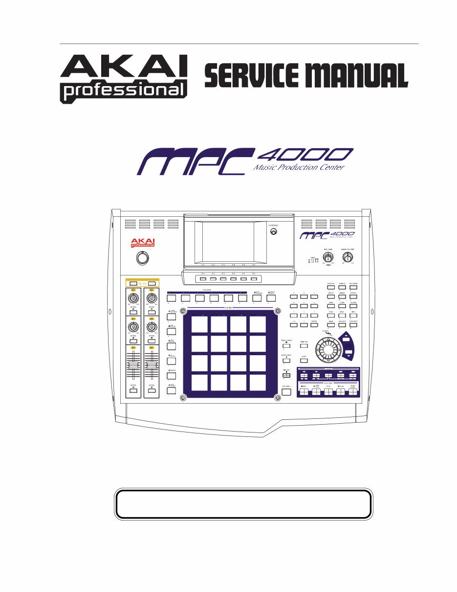
Akai MPC4000 Music production Center Service Manual
The Akai MPC4000 Music Production Center Service Manual is an essential resource for professional mechanics and DIY enthusiasts alike. This manual, available in English, provides comprehensive technical information for servicing the Akai MPC4000 Music Production Center. Whether you are troubleshooting, repairing, or maintaining the MPC4000, this manual offers detailed insights to support your needs.
With its user-friendly format, this manual is easily accessible and beneficial for individuals with varying levels of technical expertise. It is available in PDF format, ensuring convenient access for all users. The manual covers a wide range of topics, including but not limited to maintenance procedures, troubleshooting techniques, and detailed component diagrams.
Reviews
Q&A
Recently Viewed
5,521,897Happy Clients
2,594,462eManuals
1,120,453Trusted Sellers
15Years in Business
Price:
Actual Price:
Akai MPC4000 Music production Center Service Manual








 Lifetime Access




