ORDER NO. PIONEER CORPORATION 4-1, Meguro 1-chome, Meguro-ku, Tokyo 153-8654, Japan PIONEER ELECTRONICS (USA) INC. P.O. Box 1760, Long Beach, CA 90801-1760, U.S.A. PIONEER EUROPE NV Haven 1087, Keetberglaan 1, 9120 Melsele, Belgium PIONEER ELECTRONICS ASIACENTRE PTE. LTD. 253 Alexandra Road, #04-01, Singapore 159936 PIONEER CORPORATION 2005 EFX-1000 RRV3122 DJ EFFECTOR EFX-1000 THIS MANUAL IS APPLICABLE TO THE FOLLOWING MODEL(S) AND TYPE(S). Model Type Power Requirement Remarks EFX-1000 KUCXJ AC120V EFX-1000 TLTXJ AC110 - 240V EFX-1000 WYXJ AC220 - 240V EFX-1000 WAXJ AC220 - 240V For details, refer to "Important Check Points for good servicing". T-IZY JUNE 2005 printed in Japan Downloaded from www.Manualslib.com manuals search engine
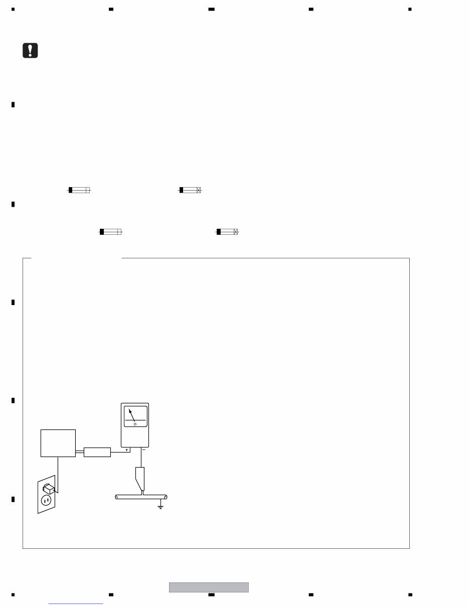
EFX-1000 2 1 2 3 4 1 2 3 4 C D F A B E SAFETY INFORMATION 1. SAFETY PRECAUTIONS The following check should be performed for the continued protection of the customer and service technician. LEAKAGE CURRENT CHECK Measure leakage current to a known earth ground (water pipe, conduit, etc.) by connecting a leakage current tester such as Simpson Model 229-2 or equivalent between the earth ground and all exposed metal parts of the appliance (input/output terminals, screwheads, metal overlays, control shaft, etc.). Plug the AC line cord of the appliance directly into a 120V AC 60 Hz outlet and turn the AC power switch on. Any current measured must not exceed 0.5 mA. ANY MEASUREMENTS NOT WITHIN THE LIMITS OUTLINED ABOVE ARE INDICATIVE OF A POTENTIAL SHOCK HAZARD AND MUST BE CORRECTED BEFORE RETURNING THE APPLIANCE TO THE CUSTOMER. 2. PRODUCT SAFETY NOTICE Many electrical and mechanical parts in the appliance have special safety related characteristics. These are often not evident from visual inspection nor the protection afforded by them necessarily can be obtained by using replacement components rated for voltage, wattage, etc. Replacement parts which have these special safety characteristics are identified in this Service Manual. Electrical components having such features are identified by marking with a > on the schematics and on the parts list in this Service Manual. The use of a substitute replacement component which does not have the same safety characteristics as the PIONEER recommended replacement one, shown in the parts list in this Service Manual, may create shock, fire, or other hazards. Product Safety is continuously under review and new instructions are issued from time to time. For the latest information, always consult the current PIONEER Service Manual. A subscription to, or additional copies of, PIONEER Service Manual may be obtained at a nominal charge from PIONEER. Leakage current tester Reading should not be above 0.5 mA Device under test Test all exposed metal surfaces Also test with plug reversed (Using AC adapter plug as required) Earth ground AC Leakage Test (FOR USA MODEL ONLY) WARNING This product contains lead in solder and certain electrical parts contain chemicals which are known to the state of California to cause cancer, birth defects or other reproductive harm. Health & Safety Code Section 25249.6 - Proposition 65 NOTICE (FOR CANADIAN MODEL ONLY) Fuse symbols (fast operating fuse) and/or (slow operating fuse) on PCB indicate that replacement parts must be of identical designation. REMARQUE (POUR MODÈLE CANADIEN SEULEMENT) Les symboles de fusible (fusible de type rapide) et/ou (fusible de type lent) sur CCI indiquent que les pièces de remplacement doivent avoir la même désignation. This service manual is intended for qualified service technicians ; it is not meant for the casual do-it- yourselfer. Qualified technicians have the necessary test equipment and tools, and have been trained to properly and safely repair complex products such as those covered by this manual. Improperly performed repairs can adversely affect the safety and reliability of the product and may void the warranty. If you are not qualified to perform the repair of this product properly and safely, you should not risk trying to do so and refer the repair to a qualified service technician. Downloaded from www.Manualslib.com manuals search engine
EFX-1000 3 5 6 7 8 5 6 7 8 C D F A B E [Important Check Points for Good Servicing] In this manual, procedures that must be performed during repairs are marked with the below symbol. Please be sure to confirm and follow these procedures. 1. Product safety Please conform to product regulations (such as safety and radiation regulations), and maintain a safe servicing environment by following the safety instructions described in this manual. 1 Use specified parts for repair. Use genuine parts. Be sure to use important parts for safety. 2 Do not perform modifications without proper instructions. Please follow the specified safety methods when modification(addition/change of parts) is required due to interferences such as radio/TV interference and foreign noise. 3 Make sure the soldering of repaired locations is properly performed. When you solder while repairing, please be sure that there are no cold solder and other debris. Soldering should be finished with the proper quantity. (Refer to the example) 4 Make sure the screws are tightly fastened. Please be sure that all screws are fastened, and that there are no loose screws. 5 Make sure each connectors are correctly inserted. Please be sure that all connectors are inserted, and that there are no imperfect insertion. 6 Make sure the wiring cables are set to their original state. Please replace the wiring and cables to the original state after repairs. In addition, be sure that there are no pinched wires, etc. 7 Make sure screws and soldering scraps do not remain inside the product. Please check that neither solder debris nor screws remain inside the product. 8 There should be no semi-broken wires, scratches, melting, etc. on the coating of the power cord. Damaged power cords may lead to fire accidents, so please be sure that there are no damages. If you find a damaged power cord, please exchange it with a suitable one. 9 There should be no spark traces or similar marks on the power plug. When spark traces or similar marks are found on the power supply plug, please check the connection and advise on secure connections and suitable usage. Please exchange the power cord if necessary. 0 Safe environment should be secured during servicing. When you perform repairs, please pay attention to static electricity, furniture, household articles, etc. in order to prevent injuries. Please pay attention to your surroundings and repair safely. 2. Adjustments To keep the original performance of the products, optimum adjustments and confirmation of characteristics within specification. Adjustments should be performed in accordance with the procedures/instructions described in this manual. 4. Cleaning For parts that require cleaning, such as optical pickups, tape deck heads, lenses and mirrors used in projection monitors, proper cleaning should be performed to restore their performances. 3. Lubricants, Glues, and Replacement parts Use grease and adhesives that are equal to the specified substance. Make sure the proper amount is applied. 5. Shipping mode and Shipping screws To protect products from damages or failures during transit, the shipping mode should be set or the shipping screws should be installed before shipment. Please be sure to follow this method especially if it is specified in this manual. Downloaded from www.Manualslib.com manuals search engine
EFX-1000 4 1 2 3 4 1 2 3 4 C D F A B E CONTENTS 1. SPECIFICATIONS ............................................................................................................................................ 5 2. EXPLODED VIEWS AND PARTS LIST ............................................................................................................ 7 2.1 PACKING SECTION .................................................................................................................................. 7 2.2 EXTERIOR SECTION................................................................................................................................ 8 2.3 CONTROL PANEL SECTION .................................................................................................................. 10 3. BLOCK DIAGRAM AND SCHEMATIC DIAGRAM .......................................................................................... 12 3.1 BLOCK DIAGRAM ................................................................................................................................... 12 3.2 OVERALL WIRING DIAGRAM................................................................................................................. 18 3.3 MAIN ASSY (1/3) ..................................................................................................................................... 20 3.4 MAIN ASSY (2/3) ..................................................................................................................................... 22 3.5 MAIN ASSY (3/3) ..................................................................................................................................... 24 3.6 CTRL (1/2), SW1 and SW2 ASSYS......................................................................................................... 26 3.7 CTRL ASSY (2/2) ..................................................................................................................................... 28 3.8 7SEG ASSY ............................................................................................................................................. 30 3.9 MIDI ASSY ............................................................................................................................................... 32 3.10 ACIN, ENCB and MVR ASSYS.............................................................................................................. 33 3.11 POWER SUPPLY UNIT.......................................................................................................................... 34 3.12 VOLTAGES ............................................................................................................................................. 36 3.13 WAVEFORMS ........................................................................................................................................ 38 4. PCB CONNECTION DIAGRAM ..................................................................................................................... 43 4.1 MAIN ASSY ............................................................................................................................................. 44 4.2 CTRL, SW1 and SW2 ASSYS ................................................................................................................. 48 4.3 MIDI, ACIN, ENCB and MVR ASSYS ...................................................................................................... 52 4.4 POWER SUPPLY UNIT............................................................................................................................ 54 5. PCB PARTS LIST ........................................................................................................................................... 56 6. ADJUSTMENT ............................................................................................................................................... 71 7. GENERAL INFORMATION ............................................................................................................................. 72 7.1 DIAGNOSIS ............................................................................................................................................. 72 7.1.1 TEST MODE ...................................................................................................................................... 72 7.1.2 REWRITING THE FIRMWARE.......................................................................................................... 78 7.1.3 POWER ON SEQUENCE.................................................................................................................. 90 7.1.4 DISASSEMBLY .................................................................................................................................. 92 7.2 PARTS...................................................................................................................................................... 94 7.2.1 IC ....................................................................................................................................................... 94 8. PANEL FACILITIES ........................................................................................................................................ 98 Downloaded from www.Manualslib.com manuals search engine
EFX-1000 5 5 6 7 8 5 6 7 8 C D F A B E 1. SPECIFICATIONS • KUCXJ type 1. General Power supply ......................................................... AC 120 V, 60 Hz Power consumption .................................................................. 16 W Operating temperature ................. +5°C to +35°C (+41°F to +95°F) Relative humidity ....................... 5% to 85% (without condensation) Weight ........................................................................ 2.4 kg (5.3 lb) Maximum external dimensions ..... 320 (W) x 234 (D) x 101 (H) mm 12-19/32 (W) x 9-7/32 (D) x 3-31/32 (H) in. 2. Audio Unit Sampling rate ........................................................................ 96 kHz A/D, D/A Resolution .............................................................. 24 bits Frequency characteristics ....................................... 20 Hz to 22 kHz S/N ratio ................................................................................. 83 dB Distortion ............................................................................... 0.02 % Headroom ................................................................................19 dB Input level ............................................... –10 dBV / +4 dBu (22 kΩ) Output level ......................................................... –10 dBV / +4 dBu (RCA pin jacks: 1 kΩ, Phone jacks: 1 kΩ) *–10 dBV / +4 dBu is switchable. 3. Input/Output terminals Audio line input terminal RCA pin jacks ............................................................................ 2 Phone jacks (1/4-inch/6.3 mm in diameter) ............................... 2 Audio line output terminal RCA pin jacks ............................................................................ 2 Phone jacks (1/4-inch/6.3 mm in diameter) ............................... 2 Digital input terminal RCA pin jack .............................................................................. 1 Digital output terminal RCA pin jack .............................................................................. 1 EFX LINK connector (mini-DIN) ..................................................... 1 MIDI input terminal (5-pin DIN) ...................................................... 1 MIDI output terminal (5-pin DIN) .................................................... 1 4. Accessories Operating instructions .................................................................... 1 Digital link cable ............................................................................. 1 Power cord ..................................................................................... 1 Warranty ......................................................................................... 1 NOTE: Specifications and design are subject to possible modification without notice. • TLTXJ type 1. General Power supply ....................................... AC 110 V - 240 V, 50/60 Hz Power consumption .................................................................. 16 W Operating temperature .............................................. +5°C to +35°C Relative humidity ....................... 5% to 85% (without condensation) Weight .................................................................................... 2.4 kg Maximum external dimensions ..... 320 (W) x 234 (D) x 101 (H) mm 2. Audio Unit Sampling rate ........................................................................ 96 kHz A/D, D/A Resolution .............................................................. 24 bits Frequency characteristics ....................................... 20 Hz to 22 kHz S/N ratio ................................................................................. 83 dB Distortion ............................................................................... 0.02 % Headroom ................................................................................ 19 dB Input level ............................................... –10 dBV / +4 dBu (22 kΩ) Output level .......................................................... –10 dBV / +4 dBu (RCA pin jacks: 1 kΩ, Phone jacks: 1 kΩ) *–10 dBV / +4 dBu is switchable. 3. Input/Output terminals Audio line input terminal RCA pin jacks ............................................................................ 2 Phone jacks (1/4-inch/6.3 mm in diameter) ............................... 2 Audio line output terminal RCA pin jacks ............................................................................ 2 Phone jacks (1/4-inch/6.3 mm in diameter) ............................... 2 Digital input terminal RCA pin jack .............................................................................. 1 Digital output terminal RCA pin jack .............................................................................. 1 EFX LINK connector (mini-DIN) ..................................................... 1 MIDI input terminal (5-pin DIN) ....................................................... 1 MIDI output terminal (5-pin DIN) ..................................................... 1 4. Accessories Operating instructions .................................................................... 1 Digital link cable ............................................................................. 1 Power cord ..................................................................................... 1 NOTE: Specifications and design are subject to possible modification without notice. Downloaded from www.Manualslib.com manuals search engine
EFX-1000 6 1 2 3 4 1 2 3 4 C D F A B E Power cord (KUCXJ : ADG7021) (TLTXJ : ADG1127) (WYXJ : ADG1127) (WAXJ : ADG7079) Accessories Digital link cable (8P DIN cable) (DKP3724) L= 2 m Operating Instructions Warranty (KUCXJ type only) • WYXJ type 1. General Power supply ....................................... AC 220 V - 240 V, 50/60 Hz Power consumption .................................................................. 16 W Operating temperature .............................................. +5°C to +35°C Relative humidity ....................... 5% to 85% (without condensation) Weight .................................................................................... 2.4 kg Maximum external dimensions ..... 320 (W) x 234 (D) x 101 (H) mm 2. Audio Unit Sampling rate ........................................................................ 96 kHz A/D, D/A Resolution .............................................................. 24 bits Frequency characteristics ....................................... 20 Hz to 22 kHz S/N ratio .................................................................................. 83 dB Distortion ............................................................................... 0.02 % Headroom ................................................................................ 19 dB Input level ............................................... –10 dBV / +4 dBu (22 kΩ) Output level .......................................................... –10 dBV / +4 dBu (RCA pin jacks: 1 kΩ, Phone jacks: 1 kΩ) *–10 dBV / +4 dBu is switchable. 3. Input/Output terminals Audio line input terminal RCA pin jacks ............................................................................ 2 Phone jacks (1/4-inch/6.3 mm in diameter) ............................... 2 Audio line output terminal RCA pin jacks ............................................................................ 2 Phone jacks (1/4-inch/6.3 mm in diameter) ............................... 2 Digital input terminal RCA pin jack .............................................................................. 1 Digital output terminal RCA pin jack .............................................................................. 1 EFX LINK connector (mini-DIN) ..................................................... 1 MIDI input terminal (5-pin DIN) ....................................................... 1 MIDI output terminal (5-pin DIN) ..................................................... 1 4. Accessories Operating instructions ..................................................................... 1 Digital link cable .............................................................................. 1 Power cord ......................................................................................1 NOTE: Specifications and design are subject to possible modification without notice. • WAXJ type 1. General Power supply ........................................AC 220 V - 240 V, 50/60 Hz Power consumption ................................................................. 16 W Operating temperature .............................................. +5°C to +35°C Relative humidity ...................... 5% to 85% (without condensation) Weight .................................................................................... 2.4 kg Maximum external dimensions...... 320 (W) x 234 (D) x 101 (H) mm 2. Audio Unit Sampling rate ........................................................................ 96 kHz A/D, D/A Resolution ............................................................... 24 bits Frequency characteristics ....................................... 20 Hz to 22 kHz S/N ratio .................................................................................. 83 dB Distortion ............................................................................... 0.02 % Headroom................................................................................ 19 dB Input level ................................................ –10 dBV / +4 dBu (22 kΩ) Output level .......................................................... –10 dBV / +4 dBu (RCA pin jacks: 1 k, Phone jacks: 1 kΩ) *–10 dBV / +4 dBu is switchable. 3. Input/Output terminals Audio line input terminal RCA pin jacks ........................................................................... 2 Phone jacks (1/4-inch/6.3 mm in diameter) ............................. 2 Audio line output terminal RCA pin jacks ........................................................................... 2 Phone jacks (1/4-inch/6.3 mm in diameter) .............................. 2 Digital input terminal RCA pin jack ............................................................................. 1 Digital output terminal RCA pin jack ............................................................................. 1 EFX LINK connector (mini-DIN) ..................................................... 1 MIDI input terminal (5-pin DIN) ...................................................... 1 MIDI output terminal (5-pin DIN) .................................................... 1 4. Accessories Operating instructions .................................................................... 1 Digital link cable ............................................................................. 1 Power cord ..................................................................................... 1 NOTE: Specifications and design are subject to possible modification without notice. Downloaded from www.Manualslib.com manuals search engine
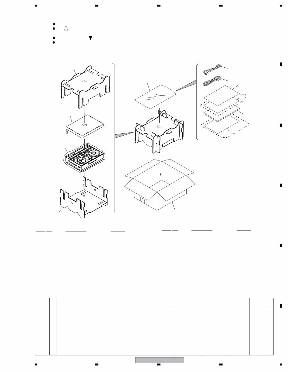
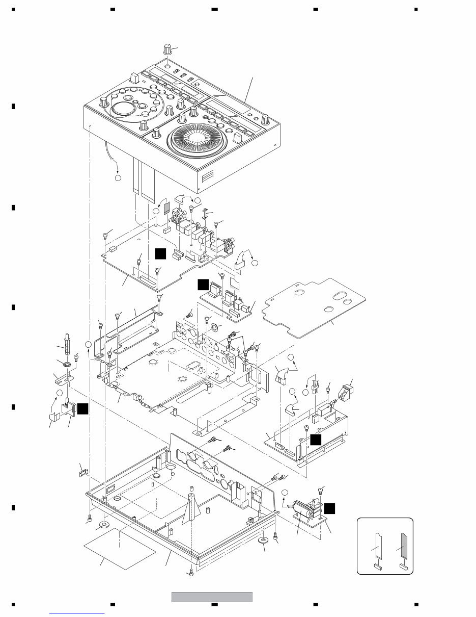
EFX-1000 7 5 6 7 8 5 6 7 8 C D F A B E 2. EXPLODED VIEWS AND PARTS LIST 2.1 PACKING SECTION (1) PACKING SECTION PARTS LIST (2) CONTRAST TABLE EFX-1000/KUCXJ, TLTXJ, WYXJ and WAXJ are constructed the same except for the following: Parts marked by "NSP" are generally unavailable because they are not in our Master Spare Parts List. The mark found on some component parts indicates the importance of the safety factor of the part. Therefore, when replacing, be sure to use parts of identical designation. Screws adjacent to mark on product are used for disassembly. For the applying amount of lubricants or glue, follow the instructions in this manual. (In the case of no amount instructions, apply as you think it appropriate.) NOTES: 7 9 11 10 8 2 4 6 3 1 5 12 KUCXJ Only WYXJ Only Mark No. Description P ar t No. > 1 Powe Cord See Contrast table (2) NSP 2 Polyethylene Bag AHG7117 3 Digital Link Cable(8P DIN Cable)DKP3724 4 Operating Instructions See Contrast table (2) NSP 5 User Registration SH DRM1262 6 WEE Caution Card See Contrast table (2) 7 Pad (A) DHA1645 8 Pad (B) DHA1687 9 Pad (C) DHA1647 10 Packing Case See Contrast table (2) 11 Sheet RHX1006 NSP 12 Limited Warranty See Contrast table (2) Mark No. Description P ar t No. Mark No. Symbol and Description EFX-1000/ KUCXJ EFX-1000/ TLTXJ EFX-1000/ WYXJ EFX-1000/ WAXJ > 1 Power Cord ADG7021 ADG1127 ADG1127 ADG7079 4 Operating Instructions (Chinise/English) DRB1367 Not used Not used Not used 4 Operating Instructions (English/Spanish/ Chinese) Not used DRB1369 Not used Not used 4 Operating Instructions (English/French/Duch/German/Italian/Spanish) Not used Not used DRB1368 Not used 4 Operating Instructions (English) Not used Not used Not used DRB1370 6 WEE Caution Card Not used Not used ARM7099 Not used 10 Packing Case DHG2476 DHG2477 DHG2475 DHG2479 NSP 12 Limited Warranty ARY7043 Not used Not used Not used Downloaded from www.Manualslib.com manuals search engine
EFX-1000 8 1 2 3 4 1 2 3 4 C D F A B E 2.2 EXTERIOR SECTION A A B B C C E E D D A F I G J CONTACT SIDE NON-CONTACT SIDE Refer to "2.3 CONTROL PANEL SECTION" . 18 17 1 13 27 28 16 20 12 15 26 14 4 6 3 12 10 28 2 5 22 21 28 8 9 19 31 31 29 29 29 29 29 7 29 29 31 29 29 30 30 30 30 30 30 29 29 29 30 23 30 28 28 Downloaded from www.Manualslib.com manuals search engine
EFX-1000 9 5 6 7 8 5 6 7 8 C D F A B E (1) EXTERIOR SECTION PARTS LIST (2) CONTRAST TABLE EFX-1000/KUCXJ, TLTXJ, WYXJ and WAXJ are constructed the same except for the following: Mark No. Description P ar t No. 1 MAIN BOARD Assy DWX2401 2 ACIN Assy See Contrast table (2) 3 MIDI Assy DWX2402 4 MVR Assy DWX2444 > 5 POWER SUPPLY Unit DWR1377 6 10P Flexible Cable DDD1293 NSP 7 Earth Lead Wire DE005VF0 8 Connector Assy DKP3725 9 Connector Assy DKP3741 > 10 Ferrite Core DTH1196 11 • • • • • 12 Insulator MO DEC2250 13 Insulation Sheet B DEC2823 14 VOL Support Plate MASTER DNF1719 15 Extension Shaft DNK4348 16 Main Shield Assy DXB1851 NSP 17 PCB Holder REC1220 18 Knob VOL DAA1168 19 Power Knob DAC1895 20 Blind Cap DNK4218 NSP 21 Chassis See Contrast table (2) 22 Block Label DRW2271 23 E Wave Sheet DEC2881 24 • • • • • 25 • • • • • 26 Nut M7 DBN1011 27 Nut M12 DBN1012 28 Screw PMH30P100FTB 29 Screw BBZ30P060FTB 30 Screw BPZ30P080FTB 31 Screw BBZ30P080FTC Mark No. Description P ar t No. Mark No. Symbol and Description EFX-1000/ KUCXJ EFX-1000/ TLTXJ EFX-1000/ WYXJ EFX-1000/ WAXJ 2 ACIN Assy DWR1382 DWR1381 DWR1381 DWR1381 NSP 21 Chassis DNK4618 DNK4621 DNK4617 DNK4620 Downloaded from www.Manualslib.com manuals search engine
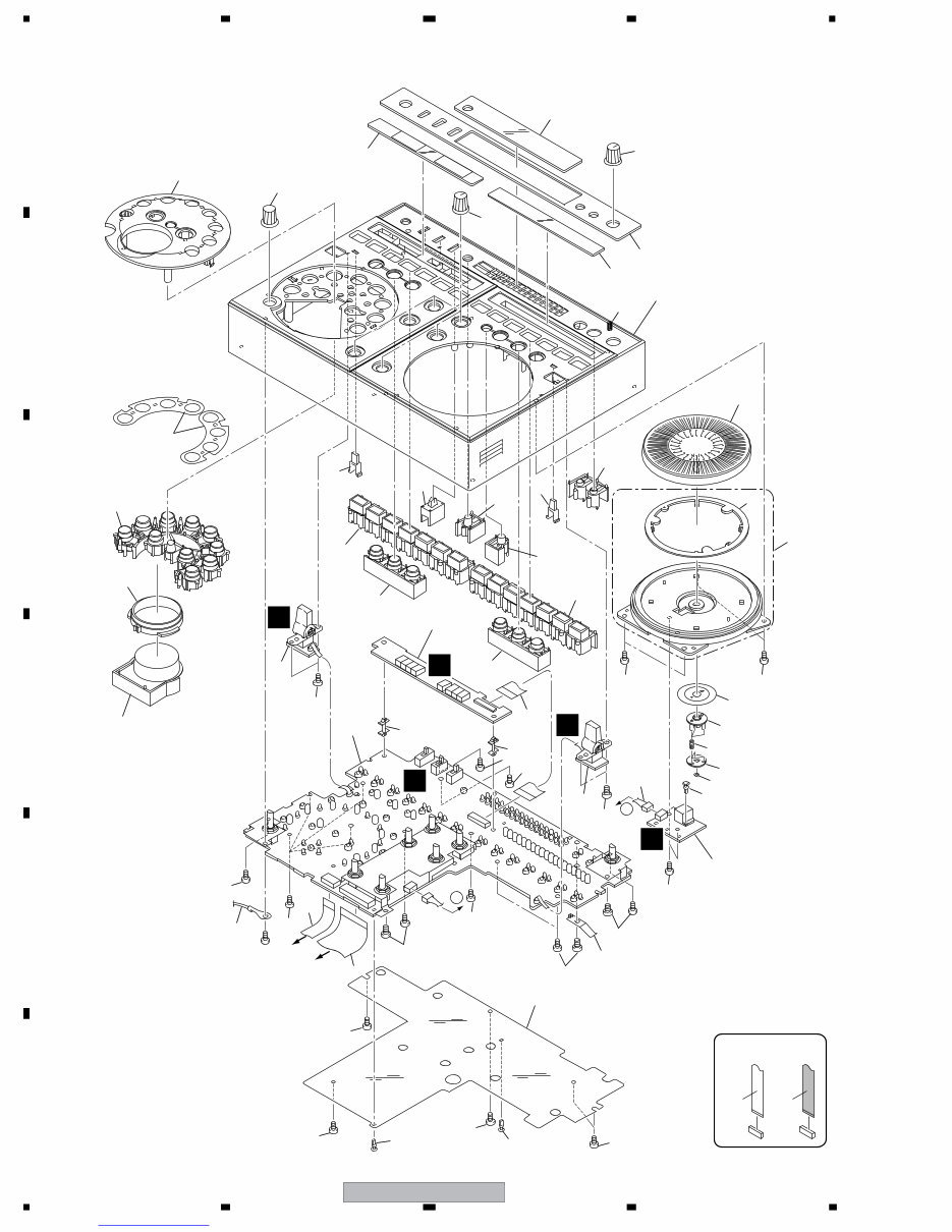
EFX-1000 10 1 2 3 4 1 2 3 4 C D F A B E 2.3 CONTROL PANEL SECTION A A E C H D B To MAIN CN102 To MAIN CN402 CONTACT SIDE NON-CONTACT SIDE 21 21 32 37 33 34 22 36 35 38 31 40 40 25 24 28 30 23 39 3 2 8 7 9 41 17 15 18 29 26 27 1 44 14 16 10 13 12 42 42 5 4 6 11 19 43 11 47 47 47 47 47 47 47 47 47 47 47 47 47 47 47 47 47 20 45 Downloaded from www.Manualslib.com manuals search engine
Are you experiencing issues with your Pioneer EFX-1000 DJ Effector?
Why spend a lot on repairs or replacements when you can easily do it yourself?
This comprehensive service and repair manual is utilized by Certified Pioneer Technicians and is equally beneficial for professional mechanics and DIY enthusiasts.
It covers a wide range of topics including:
Safety & Precautions
Product Specifications
Maintenance
Disassembly & Reassembly
Adjustments
Block Diagram
Schematic Diagram
Exploded Views
Replacement Parts list
This service manual is meticulously detailed with colored images and step-by-step instructions for effective troubleshooting and repair.
It is an official service manual in PDF format, ensuring high-resolution quality for printing.
Gain instant access after payment without any shipping delays, allowing you to commence repairs promptly.
Specifications:
Language: English
Pages: 108
Platform: Windows and MAC
If you are unable to find a specific service manual, feel free to reach out to us. With one of the largest service manual databases, we may be able to assist you.