

Repair Manual Kenwood KDC X590 CD RECEIVER
What's Included?
Fast Download Speeds
Online & Offline Access
Access PDF Contents & Bookmarks
Full Search Facility
Print one or all pages of your manual
© 2006-3 PRINTED IN JAPAN
B53-0393-00
(
N
)
960
CD RECEIVER
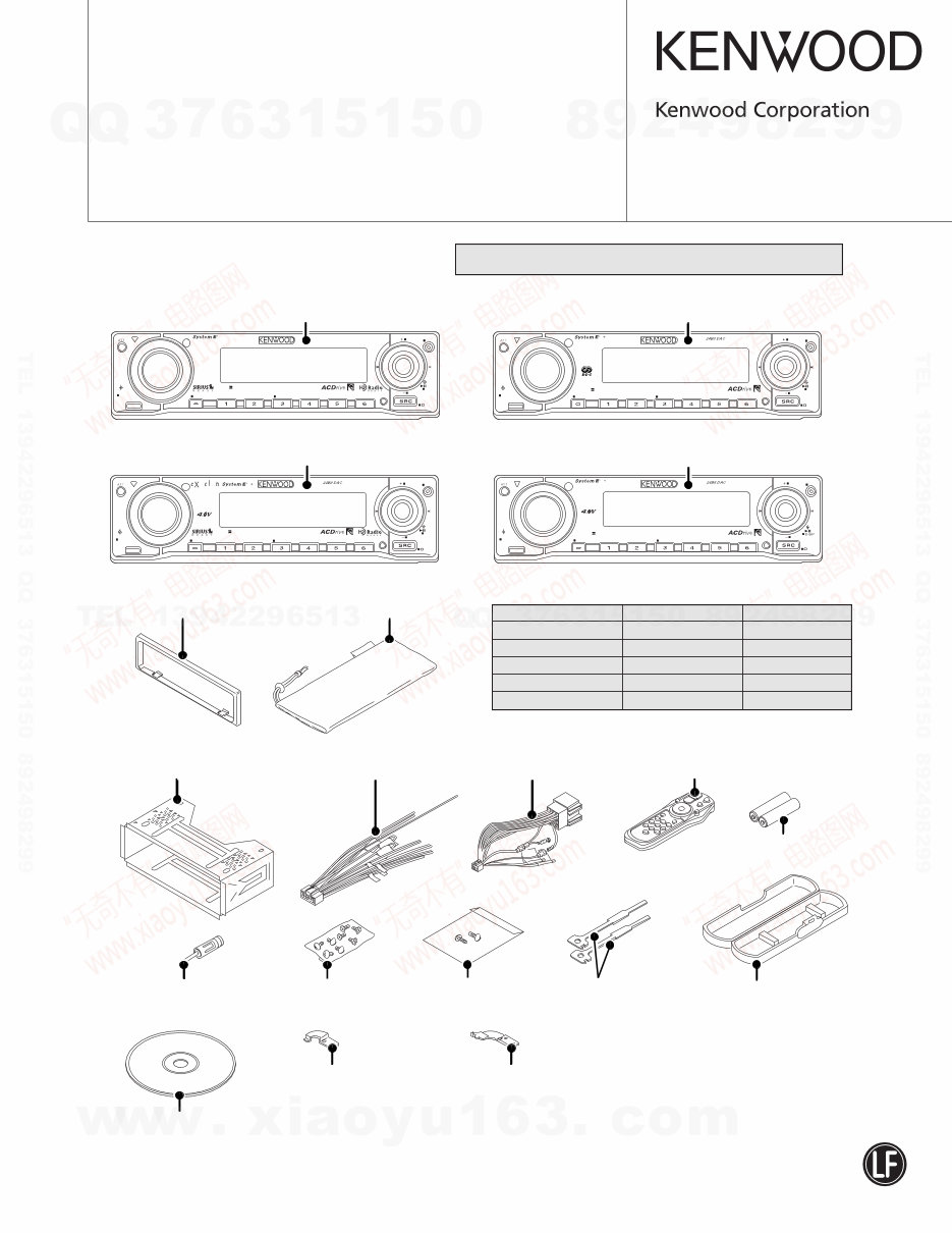
KDC-MP632U
KDC-W6534U/UY
KDC-X590
KDC-X7533U
SERVICE MANUAL
* Depends on the model. Refer to the parts list.
Panel assy
KDC-MP632U (A64-3760-01)
Panel assy
KDC-MP6534U/UY (A64-3762-01)
Mounting hardware assy
(J22-0011-03)
Lever
(D10-4589-04) x2
* DC cord
(E30-xxxx-xx)
* Screw set
(N99-1757-05)
* Escutcheon
(B07-xxxx-xx)
SPARE TDF PANEL
MAIN UNIT NAME TDF PARTS No. TDF NAME
KDC-MP632U Y33-2540-61 TDF-MP66D
KDC-W6534U Y33-2540-63 TDF-W6534U
KDC-W6534UY Y33-2540-63 TDF-W6534U
KDC-X590 Y33-2540-60 TDF-65DX
* Carrying case
(W01-xxxx-xx)
* DC cord
(E30-6412-05)
* Antenna adaptor
(T90-0523-05)
* Plastic cabinet assy
(A02-2743-03)
* Remote controller assy (RC-527)
(A70-2067-15)
Battery
(Not supplied)
Panel assy
KDC-X590 (A64-3759-01)
Panel assy
KDC-X7533U (A64-3761-01)
Mounting hardware (R)
(J22-0259-04)
Mounting hardware (L)
(J22-0258-04)
Screw set
(N99-1780-05)
KDC-X7533U Y33-2540-62 TDF-X7533U
A.RDM
RDM
VOL
AUD
SET UP
SCAN S.MODE REP Q MENU M.RDM F.SEL
KDC-X590
FF
FM SCRL AUTO
AME
s
AM SW
/C.S.
DISP USB
c o
A.RDM
RDM
S.MODE
VOL
AUD
SET UP
SCAN REP Q MENU M.RDM F.SEL
KDC-MP632U
FF
FM SCRL AUTO
AME
s
AM SW
/C.S.
DISP USB
VOL
AUD
SET UP
SCAN REP Q MENU M.RDM F.SEL
KDC-X7533U
FF
AM
FM SCRL AUTO
AME
A.RDM
RDM
S.MODE
s
SW
USB
VOL
AUD
SET UP
SCAN REP Q MENU M.RDM F.SEL
KDC-W6534U
FF
FM SCRL
A.RDM
RDM
TI
AME
S.MODE
s
AM SW
/PTY
DISP USB
* Compact disc
(W01-xxxx-xx)
CD MECHANISM EXTENSION CORD (30P) : E39-0812-05
This product uses Lead Free solder.
2
KDC-MP632U
KDC-W6534U/UY/X590/X7533U
BLOCK DIAGRAM
ELECTRIC UNIT (X34- )
SWITCH UNIT (X16- )
FRONT-END
LX-BUS
E-VOL
IC2
CD MECHA
BU5V
D5V
PREF
PRE+B
A8V
SYSTEM u-COM
BU
PW-IC
SP-OUT
LOGIC
Q400-407
PRE-OUT
PHONE
ACC-DET
Q112
DIMMER
Q108
SURGE-
Q109
BU5V
P-CON-SW
Q1,2
Q103,106
BU-DET
Q111
4V
Q15
IC5
SW14V
Q4,9
SW5V
Q3,11
ANT-CON
Q101,102
Q7,8
TUNER
Q302,303
A8V
Q5,6,10
DC-CN
TUN8V
PRE+B
SERVO+B
BU5V
SW5V
8V
PRE+B
DET
MUTE
BU
DC-CN etc
SW
EJECT
BU5V
PAN5V
FLIP
DET
RESET
IC7
ILLUMI+B
CN
RESET
ENCODER
ROTARY
REMOTE SW5V ILLUMI
KEY
MATRIX
KEY
VFD
IC1
SW5V
Q4,5
R73
PAN5V
IC4
IC2
J1
+B
ILLUMI
ILLUMI+B
ILLUMI
SW
Q305,306
AM+B
AM+B
Q300,301
S1
ED1
FL+B
J3
MUTE
IC6
J2
TUN8V
AM+B
SW5V
W1
A1
SERVO+B
A8V
S4
BU5V
BU5V
EJECT & DSI
ILLUMI
Q304 Q13
BU5V
BU5V
BU5V
J1
DME1
MARINE REMOTE
OPEL DISPLAY
BU5V
SW5V
CD
SERVO
BU5V
BU5V
BU5V
AUX IN
CN4
+B
S3
DET
to GND
FLIP
1W Rx1
S3
J1
OEM REMOTE
CN5 IC9
RDS/
RDBS
SW5V
USB
CN2,3
USB5V
C104,D107,R112
CON
EXT-AMP-
Q107
BU5V
SW20V
SURGE
Q12,21 IC12
SW REG
IC8
D5V
SW
HI-SIDE USB5V
A8V
IC13
FL+B
FL+B
J4
7 1 3
2
10
1
REAR L/R
FRONT L/R
FRONT/REAR/(NF)
SW5V
ANT CON
P-CON
BU DET
ACC
ILLUMI
PHONE
P-ANT
P-CON
B.U.
MUTE DC-DET
PHONE
ACC DET
DIMMER
1
1
2
RST
PHONE
9
5
P.ON
P.ON
P.ON
P.ON
P.ON ILLUMI
AM+B
SELECT
COLOR
BU DET
Q111
Q114
1
1
3
MUTE
3 8
1 2
3
NF L/R
EXT-CONT
FST
P.ON USB/CURRENT DET
2
EX-AMP
P.ON CD
P.ON
DIMMER/
BU DET/
P-CON/P.ON
P.ON CD/
P.ON FL/
ACC DET
P.ON ILLUMI
EX-AMP
ANT CON
P.ON USB CURRENT DET
P.ON FL
KDC-MP632U
KDC-W6534U/UY/X590/X7533U
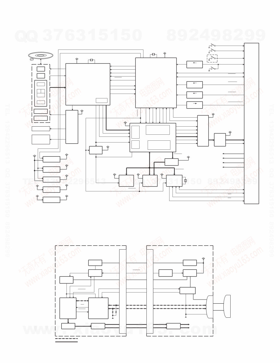
3
BLOCK DIAGRAM
CD PLAYER UNIT (X32-5830-00)
TR COIL
FO COIL
C
F
A B
E
PD
LD
SERVO DSP
MOTOR
DRIVER
SP MOTOR
LOADING &
MOTOR
SLED
IC4
IC2
u-COM
IC1
IC15
IC5
SW3.3V
3V REG
IC21
1.8V REG
IC20
IC19
BU3.3V REG
IC14
A5V REG
DAC
3.3 5V
LPF
IC18
IC13
64Mbit
SDRAM
IC16
MEMORY
FLASH
IC17
8Mbit
D5V (D4V)
S7.5V
A8V
BU5V
AUDIO DSP
DM2
DM1
DPU1
Q7
(SW3.3V)
S4
ONLY
0-01
S2
S1
S3
(BU5V)
3.3
Q6
5V
RESISTOR
3.3
R6,8
5V
(BU5V)
Q3
3.3 5V
3-STATE
BUFFER
IC28
GATE
NAND
IC26
DRIVER
USB
IC25
to X34-
16.893MHz
SW3.3V
S7.5V
RESET
SCK
SI
STB
A0
SO
INTQ
POWER ON 11.500MHz
BU3.3V
D5V
CKO
SW3.3V
CS3.3V
CS1.8V
POWER
BU3.3V
SW A5V
BU5V
A8V
SER2 (3/4WIRE)
LOE/LIM-
8EJE-SW
LOS-SW
12EJE-SW
AUDIO Lch
CS3.3V
CONTROLLER
MEMORY
CS3.3V CS3.3V
SW A5V
I2S
CD I/F
CS3.3V
CS1.8V
&
CS POWER
CS POWER
X1
DA EMPH
I2CDATA
I2CCLK
MRESET
MSTOP
AUDIO MUTE
EMPH
INFINITY 0 DET.
CSRST
S DATA
DATA MUTE
B DATA
CLK
SREQ
BREQ
CS EMPH
DAC RST
DAC MUTE
PCM XCK
PCM DATA
PCM LRCK
PCM BCLK AUDIO Rch
SW A8V
CS3.3V
DATA
LRCK
BCLK
C16
PLL
CS, A20
CS3.3V
CS3.3V
USB CS
X2
6.00MHz
X3
USB D+
USB D-
OC
PO
CSRST
UHC124
ELECTRIC UNIT (X34-) CD PLAYER UNIT (X32-)
u-COM
SESTEM
AUDIO LINE
CONTROLLER
USB HOST
DAC
IC18
DSP
USB LINE
LFP
IC13
BU3.3V
IC25
u-COM
MECHA-
IC1
IC19
IC15
CS3.3V
(CS1.8V)
IC20,21
CONNECTOR
CN1
CONNECTOR
IC1
CN1
CONNECTOR
E-VOL
IC2
USB
5V
SW-REG.
HIGH-SIDE
SWITCH
IC8
IC12
Q1,2
BU5V
CN2 or CN3
RESET
INT
Rch
USB D+
USB D-
Lch
CSRST
P-ON
POWER ON SW
OVER CURRENT
D5V
BU5V
MSTOP
USB GND
USB D-
USB D+
CABLE
BU14V
P-ON
(V-BUS 5V)
USB 5V
4
KDC-MP632U
KDC-W6534U/UY/X590/X7533U
COMPONENTS DESCRIPTION
● ELECTRIC UNIT (X34-415x-xx)
Ref. No. Application / Function Operation / Condition / Compatibility
IC1 System µ-COM Controls FM/AM tuner, the changer, CD mechanism, panel, volume and tone.
IC2 E-VOL Controls the source, volume, tone.
IC3 A8V REF Power Supply Outputs 1.27V.
IC4 Power IC Amplifies the front L/R and the rear L/R to 50W maximum.
IC5 ILLUMI+B Power Supply Outputs 11.25V.
IC6 Muting Logic IC Controls logic for muting.
IC7 Reset IC “Lo” when detection voltage goes below 3.6V or less.
IC8 Hi-side SW
Over current protection of USB power supply.
When pin 1 goes “Hi”, USB5V is ON.
IC9 RDS IC Decodes RDS.
IC10 Installer Memory IC Installer memory.
IC11 Analog IC OP-AMP.
IC12 SW Regulator Supplies power for USB and CD mechanism.
IC13 FL+B Power Supply Outputs 3.0V.
Q1,2 B.U.5V AVR While BU is applied, BU5V AVR outputs +5V.
Q3,11 SW5V When Q11’s base goes “Hi”, SW5V outputs +5V.
Q4,9 SW14V When Q9’s base goes “Hi”, SW14V outputs 14V.
Q5,6,10 AUDIO8V AVR When Q10’s base goes “Hi”, A8V AVR outputs 8.0V.
Q7,8 SERVO+B AVR When Q8’s base goes “Hi”, S+B AVR outputs 7.5V.
Q12,21 Serge Protect for IC12 Outputs 20V when BU is over 20V.
Q13 PANEL5V When the base goes “Lo”, PANEL5V outputs 5V.
Q14,16 4V-PRE+B Protect When 4V-PRE+B is over current, Q14 and Q16 make Q15 turns off.
Q15 4V-PRE+B AVR When the base is 8V, 4V-PRE+B outputs 7.4V.
Q17 IC12 ON/OFF When the base goes “Lo”, IC12 is “ON”.
Q101,102 P-ANT SW When Q102’s base goes “Hi”, P-ANT SW outputs 14V.
Q103,106 P-CON SW When Q106’s base goes “Hi”, AVR outputs 14V.
Q104,105 P-CON Protection
Output protection is applied when P-CON output voltage fall is detected.
The 2 transistors protect Q103 false operation when P-CON SW is “ON”.
Q107 EXT-AMP-CON When the base goes “Lo”, Q107 is turned on.
Q108 Small Lamp DET SW When the base goes “Hi”, Q108 is turned on.
Q109 Serge DET When the base goes “Hi”, IC4 is changed into standby source.
Q111 BU DET When the base goes “Hi”, Q111 is turned on.
Q112 ACC DET When the base goes “Hi”, Q112 is turned on.
Q113 Mute Driver When the base goes “Hi”, pre-out mute driver is turned on.
Q116 Pre-out Mute Driver When the base goes “Lo”, mute driver is turned on.
Q300,301 AM+B When Q301’s base goes “Hi”, AM+B is output.
Q302,303 Tuner8V When Q303’s base goes “Hi”, Tuner8V outputs 8V.
Q304 DSI When the base goes “Hi”, security indicator lights.
Q305,306 SW ILLUMI+B When Q306’s base goes “Hi”, SW ILLUMI+B outputs 11V.
Q400~407 Pre-out Mute SW When the base goes “Hi”, pre-out is muted.
Q408 Pre-out Mute ON/OFF When the base goes “Lo”, pre-out mute is "ON".

KDC-MP632U
KDC-W6534U/UY/X590/X7533U
5
● SWITCH UNIT (X16-374x-xx)
Ref. No. Application / Function Operation / Condition / Compatibility
IC2 Remote Control IC
Q4,5 SW5V The power supply of IC2 is turned on when Q5’s base level goes “Hi”.
Q10 GREEN SW When the base goes “Hi”, LED lights.
Q12~14 Grid Driver Each grid is ON when each transistor’s base is “Lo”.
Q15 RED SW When the base goes “Hi”, LED lights.
Q18 SUB ILLUMI SW When the base goes “Hi”, LED lights.
Q19 DBO ILLUMI SW When the base goes “Hi”, LED lights.
Q20 Key Scan Start SW Key scan starts when the base goes “Hi”.
● CD PLAYER UNIT (X32-5830-00)
Ref. No. Application / Function Operation / Condition / Compatibility
IC1 Mechanism µ-COM
IC2 Signal Processor
IC4 BTL Driver
Spindel motor, sled (including loading & eject) motor and pick-up
actuator
IC5 SW3.3V Regulator 3.3V power supply for IC2, pick-up, IC18 digital part
IC13 Audio Active Filter 2nd LPF
IC14 A5V Regulator 3.3V power supply for DAC
IC15 DSP for Compression Audio Decoder ACDrive decoder, MP3/WMA/AAC decoder
IC16 Compression Audio Codec SDRAM
IC17 Decoder Software & Unique ID Strage Flash ROM
IC18 Audio D-A Converter (24-bit external) External 24-bit for audio
IC19 BU3.3V Regulator 3.3V power supply for µ-com
IC20 1.8V Regulator 1.8V power supply for IC15 core part
IC21
Decoder/SDRAM/Flash ROM/USB Driver 3.3V Power supply for decoder, SDRAM, flash ROM and USB driver.
Regulator 3.3V power supply for IC15 port parts, IC16, IC17, IC25, IC26 and IC28.
IC25 USB Host Controller
IC26
Switching among IC15 & Flash ROM &
For DSP for Compression Audio Decoder, Flash ROM, SDRAM and USB
SDRAM & USB
IC28 Clock SW To SDRAM
Q3 Level Shift 3.3V→5V
Q6,7 Level Shift 3.3V←5V
Q8 APC (Auto Power Control)
Q9,10 Anticipation Sub-beam Delay During non-searching
Q17 USB Hi-side SW
D2 Static Electricity Countermeasure For IC2 built-in reset terminal
D3 Laser Diode Protection
D9 Static Electricity Countermeasure
COMPONENTS DESCRIPTION
6
KDC-MP632U
KDC-W6534U/UY/X590/X7533U
MICROCOMPUTER’S TERMINAL DESCRIPTION
● SYSTEM µ-COM: IC1 on X34- (ELECTRIC UNIT)
Pin No. Pin Name I/O Application
Truth
Processing / Operation / Description
Value Table
1 REMO I Remote control signal input Detects pulse width
2 LX MUTE I Mute request from slave unit H: Mute ON, L: Mute OFF
3 AUD SDA O E-VOL data output
4 AUD SEL O E-VOL control
5 AUD SCL O E-VOL clock output
6 BYTE -
7 CNVSS -
8 XCIN I
9 XCOUT I
10 RESET -
11 XOUT -
12 VSS -
13 XIN - 12.0MHz
14 VCC1 -
15 NMI - Not used
16 CN DET I
Panel communication detection
H: Panel detached, L: Panel attached
(Flip-down panel model only)
17 RDS CLK I RDS decoder clock input
18 LX REQ S I Communication request from slave unit
19 PON AM I/O AM power supply control H: Receiving AM, Hi-z: No AM
20 LX REQ M O Communication request to slave unit
21 TUN IFC OUT I Front-end IFC-OUT input H: Station found, L: No station
22 NC - Not used L fixed
23 RDS AFS M I/O Noise detection time constant switching q Refer to the truth value table
24 RDS QUAL I RDS decoder QUAL input
25 RDS DATA I RDS decoder data input
26 PWIC BEEP O Beep output
27 TUN SCL I/O Front-end I2C clock input and output MAX400kHz
28 TUN SDA I/O Front-end I2C data input and output
29 VFD DATA I/O VFD data input and output
30 VFD INT I VFD INT input INT input
31 VFD CLK O VFD clock output Normal: 125kHz, Low consumption mode: 62.5kHz
H: Canceling reset, L: Reset
32 VFD RST O VFD driver reset L: Momentary power down, panel detached or 11
minutes after ACC OFF
33 ROMCOR SDA I/O
E2PROM I2C data input and output for
ROM correction
34 ROMCOR SCL I/O E2PROM I2C clock output for ROM correction
Panel 5V control
L: ON
35 PON PANEL I/O
(Flip-down panel model only)
Hi-Z: Momentary power down, panel detached or 11
minutes after ACC OFF
36 DSI I/O
DSI/EJECT LED control OFF: Hi-z, Pulse drive: Panel detached
(Flip-down panel model only) H: Illumination ON or panel opened (POWER ON)
37,38 NC - Not used L fixed
KDC-MP632U
KDC-W6534U/UY/X590/X7533U
7
Pin No. Pin Name I/O Application
Truth
Processing / Operation / Description
Value Table
39 EPM I Flash EPM input
40 PANEL DET I Panel detection (Flip-down panel model only) L: Panel detached, H: Panel attached
41 NC - Not used L fixed
42 ROMCOR DET I E2PROM writing request H: Writing
43 PON FL O FL+B control H: FL+B ON, L: FL+B OFF
44 VFD CS O VFD chip select control
45 ROTARY CW I VOL key input Detects pulse width
46 ROTARY CCW I VOL key input Detects pulse width
47 CD DISC12 SW I 12cm CD detection
48 CD LOS SW I CD loading detection
49 CD MUTE R I Rch CD mute request H: Normal, L: Requesting Rch mute
50 CD MUTE L I Lch CD mute request H: Normal, L: Requesting Rch mute
51 CD MRST O CD mecha µ-COM reset H: Normal, L: Reset
52 CD MSTOP O CD mechanism µ-COM stop H: Mecha µ-COM operates, L: Mecha µ-COM stops
53 CD DISC8 SW I 8cm CD detection (Not used)
54 CD LOE LIM SW I CD detection (Chucking SW) H: Loading completes, L: No disc
55 CD LOEJ I/O CD motor control w Refer to the truth value table
56 CD MOTOR O CD motor control w Refer to the truth value table
57 PON ILLUMI I/O Key illumination power supply control H: ON, Hi-Z: OFF
58 PON CD O Power supply control for CD-WMA
L: POWER ON, H: POWER OFF
L: Before M-STOP with reset
59 PON O Power supply H: POWER ON, L: POWER OFF
60 VCC2 -
61 EXT AMP CON I/O EXTERNAL AMP control
62 VSS -
63~65 TYPE 1~3 I Destination switching e Refer to the truth value table
66 TUN TYPE1 I Destination setting 1 r Refer to the truth value table
67 TUN TYPE2 I Destination setting 2 r Refer to the truth value table
68 OEM DISP DATA I/O External display data (Destination K and E only) External display
69 OEM DISP CLK I/O External display clock (Destination K and E only) External display
70 OEM DISP CE I/O
External display control request
External display
(Destination K and E only)
71 EJECT I Eject key input (Flip-down panel model only) L: Eject
72 P CON O External amplifier control H: POWER ON, L: POWER OFF or STANDBY
73 VFD KEY REQ I Communication request from VFD driver Connects to INT
74 ANT CON O Power antenna control Tuner ON: H
75 ILLUMI DET I Dimmer illumination detection L: ON, H: OFF
76 BU DET I Momentary power-down detection L: BU found, H: No BU or momentary power down
77 ACC DET I ACC power supply detection L: ACC found, H: No ACC
78 (PWIC SVR) O SVR discharging circuit
H: POWER OFF or 5 seconds after momentary power
down, L: Other conditions
79 PWIC MUTE O Power IC mute L: STANDBY, momentary power down or TEL mute
80 PWIC STBY O Power IC standby control H: POWER ON, L: POWER OFF
81 LX CON O Start-up request to slave unit H: Slave unit starts up, L: Slave unit stops
MICROCOMPUTER’S TERMINAL DESCRIPTION
8
KDC-MP632U
KDC-W6534U/UY/X590/X7533U
Pin No. Pin Name I/O Application
Truth
Processing / Operation / Description
Value Table
82 MUTE PRE R O Rch preout mute
CD MUTE R is Lo: H (CD playing), Momentary power
down: H, L: DUAL ZONE or NAVI INT
83 MUTE PRE L O Lch preout mute
CD MUTE L is Lo: H (CD playing), Momentary power
down: H, L: DUAL ZONE or NAVI INT
84 MUTE 0 I/O E-VOL front mute L: Mute ON, Hi-Z: Mute OFF
85 MUTE 1 I/O E-VOL rear mute L: Mute ON, Hi-Z: Mute OFF
86 MUTE 2 I/O E-VOL mute (Except front/rear)
87 LINE MUTE I Line mute detection
TEL mute: Below 1V
NAVI mute: Over 2.5V
88 MUTE PRE SW I/O NF preout mute
L: Mute ON, Hi-Z: Mute OFF
OFF fixed: Selecting REAR in REAR/SUB selection
89 PWIC DC DET I DC offset error detection
90 LX RST O Forced reset to slave unit H: Reset, L: Normal
91 MUTE C I/O E-VOL mute L: Mute ON, Hi-Z: Mute OFF
92 NC - Not used L fixed
93 RDS NOISE I FM noise detection
94 AVSS -
95 TUN SMETER I S-meter input
96 VREF - Connects to P.ON
97 AVCC - Connects to VCC
98 LX DATA S I Data from slave unit
99 LX DATA M I/O Data from and to slave unit
100 LX CLK I/O LX-BUS clock
MICROCOMPUTER’S TERMINAL DESCRIPTION
Truth value table
q AFS CONTROL
RDS AFS M Condition
AFS LOW L No sound output with AF search
AFS MID L Sound output with AF search
AFS HIGH Hi-Z Normal reception
w CD MOTOR CONTROL
CD MOTOR CD LOADING/EJECT
Stop L L
Load H L
Eject H H
Brake H Hi-z
r TUNER TYPE
TUN TYPE1 TUN TYPE2
(Pin 66) (Pin 67)
Kenwood brand model L L
OEM model 1 L H
OEM model 2 H L
OEM model 3 H H
e DESTINATION SW
TYPE 3 TYPE 2 TYPE 1
DESTINATION MODEL
(Pin 65) (Pin 64) (Pin 63)
0 0 0 K KDC-X590
0 0 1 K KDC-MP632U
0 1 0 E KDC-W6534U/UY
0 1 1 E DPX501U/UY
1 0 0 M KDC-X7533U
1 0 1 M DPX-MP2090U
1 1 0 K DPX501
1 1 1 J DPX-U077
KDC-MP632U
KDC-W6534U/UY/X590/X7533U
9
MICROCOMPUTER’S TERMINAL DESCRIPTION
● MECHANISM µ-COM: IC1 (X32-: CD PLAYER UNIT)
Pin No. Pin Name I/O Application Processing / Operation / Description
1~5 NC - Not used Opened output L fixed
6 BYTE I External data bus SW input Connects to GND
7 CNVSS I Processor mode SW
L: Single chip mode
H: Microprocessor mode or flash ROM writing
8 MUTE O Audio mute control L: Mute ON, H: Mute OFF
9 NC - Not used Opened output L fixed
10 RESET I Reset detection L: Reset (Flash ROM writing), H: Normal
11 XOUT O Main clock output Connects to resonator
12 VSS - Power supply input Connects to GND
13 XIN I Main clock input Connects to resonator
14 VCC1 - Power supply input Connects to BU3.3V
15 NMI I NMI interruption input Input Hi (Pull-up) fixed
16 MSTOP I STANDBY comeback interrupption L: Stop, H: Stop cancelled (Hi edge)
17 NC - Not used Opened output L fixed
18 DSP INT I DSP interruption signal input H: Interruption (Hi edge)
19~22 NC - Not used Opened output L fixed
23 E2P SCL I/O E2P I2C clock output
Series resistors and E2PROM are not built when
ROM collection is not used.
24 E2P SDA I/O E2P I2C data input and output
Series resistors and E2PROM are not built when
ROM collection is not used.
25,26 NC - Not used Opened output L fixed
27 SCL I System µ-com I2C clock input
28 SDA I/O System µ-com I2C data input and output
29 DSP TXD O Data output for DSP serial data Flash ROM writing: TXD (Pull-up)
30 DSP RXD I Data input for DSP serial data Flash ROM writing: RXD
31 DSP CLK O Clock output for DSP serial data Flash ROM writing: SCLK(Pull-up)
32 DSP STB(BUSY) O DSP data strove signal output Flash ROM writing: BUSY
33 CS SDATA O Data output for decoder serial data
34 CS BDATA I Data input for decoder serial data
35 CS CLK O Clock output for decoder serial data
36~38 NC - Not used Opened output L fixed
39 EPM - Not used (Flash ROM: EPM) Opened output L fixed
40 PON D3.3 O D3.3V POWER ON control H: POWER ON, L: POWER OFF
41 PON A5 O A5.0V POWER ON control H: POWER ON, L: POWER OFF
42 PON CS1 O IC15 series 3.3V POWER ON control H: POWER ON, L: POWER OFF
43 PON CS2 O IC15 series 1.8V POWER ON control H: POWER ON, L: POWER OFF
44 CE - Not used (Flash ROM: CE) Opened output L fixed
45 DRV MUTE O Driver mute L: Stop, H: Mute OFF
46,47 NC - Not used Opened output L fixed
48 ZERO M I 0-bit mute detection
H: Mute ON, L: Mute OFF
(No distinction of Lch/Rch)
49 DE-EMPHASIS O DAC de-emphasis control H: De-emphasis ON, L: De-emphasis OFF
50,51 NC - Not used Opened output L fixed
52 LIM SW I
Laser pick-up inner circumference detection
H: Inner circumference
SW signal input
10
KDC-MP632U
KDC-W6534U/UY/X590/X7533U
MICROCOMPUTER’S TERMINAL DESCRIPTION
Pin No. Pin Name I/O Application Processing / Operation / Description
53 DISC NORMAL O Media discrimination result output (Not used) H: Normal disc, L: Other disc
54 DISC H RW O Media discrimination result output (Not used) H: High reflecting RW disc, L: Other disc
55 DISC RW O Media discrimination result output (Not used) H: Normal RW disc, L: Other disc
56~59 TEST OUT4~1 O Output for test Opened output L fixed
60 VCC2 - Power supply input Connects to BU3.3V
61 TEST OUT0 O Output for test Opened output L fixed
62 VSS - Power supply input Connects to GND
63~66 NC - Not used Opened output L fixed
67 TEST IN3 I TEST IN3 Pull-down connection (L: Normal/H: During test)
68 MODEL SEL I Model determination L: DXM-6810W (X32-583), H: DXM-6820W (X32-587)
69 E2P WRITE I TEST IN1: E2P writing permission Pull-down connection (L: Normal/H: During writing)
70 UNIQ ID I TEST IN0: Uniqe ID writing permission Pull-down connection (L: Normal/H: During writing)
71~73 NC - Not used Opened output L fixed
74 SEARCH O Searching situation output H: During seaching, L: Normal
75,76 NC - Not used Opened output L fixed
77 DSP RST O DSP reset control L: Reset, H: Normal
78 DSP A0 O
DSP command/parameter discrimination H: During parameter transmitting
signal output L: During command transmitting
79 DA EMPHASIS I DSP DA emphasis input H: emphasis ON, L: emphasis OFF
80 ROM EMPHASIS I Decoder ROM emphasis input H: emphasis ON, L: emphasis OFF
81 DATA MUTE O Data output status L: During data output muting, H: During data output
82 CS RST O Decoder reset control L: Reset, H: Nornal
83 NC - Not used Opened output L fixed
84 SREQ O Decoder SREQ signal output
85 BREQ I Decoder BREQ signal input
86~93 NC - Not used Opened output L fixed
94 AVSS - Analog power supply input Connects to GND
95 NC - Not used Opened output L fixed
96 VREF - Reference voltage input Not used: Connects to GND
97 AVCC - Analog power supply input Connects to BU3.3V
98~100 NC - Not used Opened output L fixed
You're Reading a Preview
What's Included?
Fast Download Speeds
Online & Offline Access
Access PDF Contents & Bookmarks
Full Search Facility
Print one or all pages of your manual
$31.99
$41.99
Viewed 99 Times Today


Secure transaction
What's Included?
Fast Download Speeds
Online & Offline Access
Access PDF Contents & Bookmarks
Full Search Facility
Print one or all pages of your manual
$31.99
$41.99
Get your hands on the service manual for the Kenwood KDC X590 CD RECEIVER. This manual is a valuable resource for anyone looking to repair, rebuild, maintain, or service their CD receiver, whether you're a professional mechanic or a DIY enthusiast.
- The manual includes a block diagram and detailed component descriptions, making it easier to understand the inner workings of the CD receiver.
- You'll also find terminal descriptions for microcomputers, test mode instructions, installer memory specifications, and backup memory specifications.
- With 44 pages in total, the manual covers PC board layouts, schematic diagrams, exploded views, parts lists, and specifications.
- It's available in English and compatible with both Windows and Mac systems.
- This printable manual provides easy-to-follow, step-by-step instructions, along with helpful diagrams and pictures, eliminating the need for extensive technical knowledge or skills.
- By having this manual on hand, you can save money on repair and maintenance costs, avoiding overpriced services from repair shops or mechanics.
Don't miss out on the opportunity to have your own copy of this valuable resource!


