

Sony CDP-CX300/CX350/CX691 COMPACT DISC PLAYER Service Manual
What's Included?
Fast Download Speeds
Online & Offline Access
Access PDF Contents & Bookmarks
Full Search Facility
Print one or all pages of your manual
– 1 –
MICROFILM
CDP-CX300/CX350/CX691
US Model
CDP-CX300/CX350/CX691
Canadian Model
CDP-CX300/CX350
AEP Model
UK Model
Australian Model
CDP-CX350
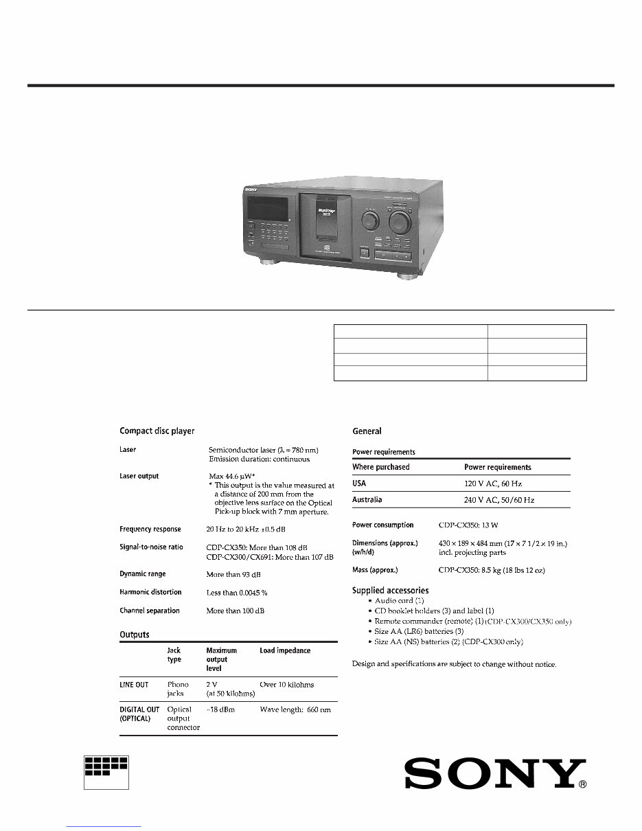
SPECIFICATIONS
SERVICE MANUAL
COMPACT DISC PLAYER
Model Name Using Similar Mechanism NEW
CD Mechanism Type CDM54-KIBD35E
Base Unit Type KSM-213BFN/M-NP
Optical Pick-up Type KSS-213BFN
Photo; CDP-CX350
Downloaded from www.Manualslib.com manuals search engine
– 2 –
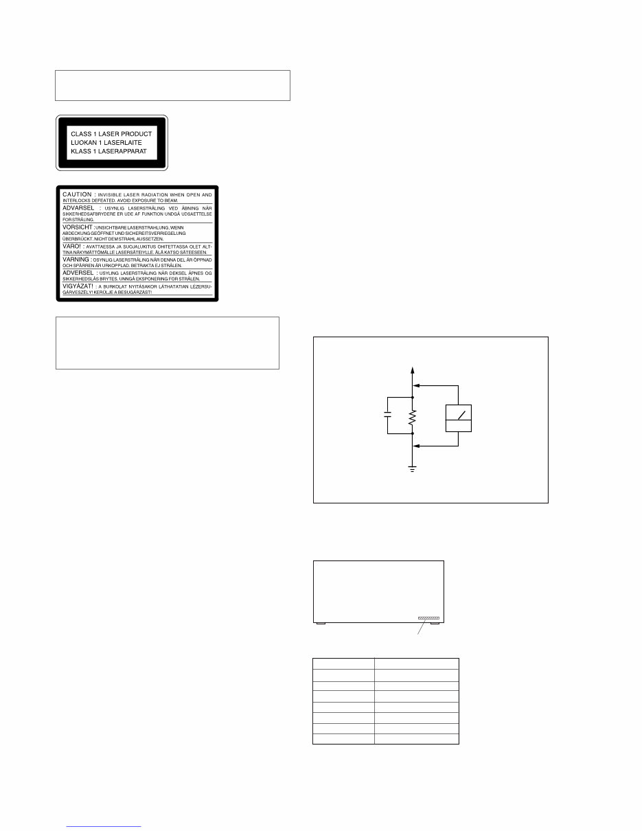
CAUTION
Use of controls or adjustments or performance of procedures
other than those specified herein may result in hazardous ra-
diation exposure.
Notes on chip component replacement
• Never reuse a disconnected chip component.
• Notice that the minus side of a tantalum capacitor may be
damaged by heat.
Flexible Circuit Board Repairing
• Keep the temperature of soldering iron around 270˚C
during repairing.
• Do not touch the soldering iron on the same conductor of the
circuit board (within 3 times).
• Be careful not to apply force on the conductor when soldering
or unsoldering.
Laser component in this product is capable of emitting radiation
exceeding the limit for Class 1.
This appliance is classified as
a CLASS 1 LASER product.
The CLASS 1 LASER PROD-
UCT MARKING is located on
the rear exterior.
The following
caution label is
located inside of
the unit.
PARTS No. MODEL
MODEL IDENTIFICATION
— BACK PANEL —
4-215-964-0π
4-215-964-1π
4-215-964-2π
4-215-964-3π
4-215-964-4π
4-215-964-5π
4-215-964-7π
CX300 : US
CX300 : CND
CX350 : US
CX350 : CND
CX350 : AEP, UK
CX350 : AUS
CX691 : US
SAFETY-RELATED COMPONENT WARNING !!
COMPONENTS IDENTIFIED BY MARK ! OR DOTTED LINE
WITH MARK ! ON THE SCHEMATIC DIAGRAMS AND IN
THE PARTS LIST ARE CRITICAL TO SAFE OPERATION.
REPLACE THESE COMPONENTS WITH SONY PARTS
WHOSE PART NUMBERS APPEAR AS SHOWN IN THIS
MANUAL OR IN SUPPLEMENTS PUBLISHED BY SONY.
ATTENTION AU COMPOSANT AYANT RAPPORT
À LA SÉCURITÉ!!
LES COMPOSANTS IDENTIFIÉS PAR UNE MARQUE !
SUR LES DIAGRAMMES SCHÉMATIQUES ET LA LISTE
DES PIÈCES SONT CRITIQUES POUR LA SÉCURITÉ DE
FONCTIONNEMENT. NE REMPLACER CES COMPOSANTS
QUE PAR DES PIÈCES SONY DONT LES NUMÉROS
SONT DONNÉS DANS CE MANUEL OU DANS LES
SUPPLÉMENTS PUBLIÉS PAR SONY.
SAFETY CHECK-OUT
After correcting the original service problem, perform the follow-
ing safety checks before releasing the set to the customer:
Check the antenna terminals, metal trim, “metallized” knobs, screws,
and all other exposed metal parts for AC leakage. Check leakage as
described below.
LEAKAGE
The AC leakage from any exposed metal part to earth Ground and
from all exposed metal parts to any exposed metal part having a
return to chassis, must not exceed 0.5 mA (500 microampers). Leak-
age current can be measured by any one of three methods.
1. A commercial leakage tester, such as the Simpson 229 or RCA
WT-540A. Follow the manufacturers’ instructions to use these
instruments.
2. A battery-operated AC milliammeter. The Data Precision 245
digital multimeter is suitable for this job.
3. Measuring the voltage drop across a resistor by means of a VOM
or battery-operated AC voltmeter. The “limit” indication is 0.75
V, so analog meters must have an accurate low-voltage scale.
The Simpson 250 and Sanwa SH-63Trd are examples of a pas-
sive VOM that is suitable. Nearly all battery operated digital
multimeters that have a 2V AC range are suitable. (See Fig. A)
Fig. A. Using an AC voltmeter to check AC leakage.
PART NO.
0.15μF
To Exposed Metal
Parts on Set
1.5kΩ
AC
voltmeter
(0.75V)
Earth Ground
• Abbreviation
CND : Canadian model
AUS : Australian model
Downloaded from www.Manualslib.com manuals search engine

– 3 –
TABLE OF CONTENTS
1. SERVICING NOTE .......................................................... 3
2. GENERAL .......................................................................... 6
3. DISASSEMBLY
3-1. Front Panel Assembly ........................................................... 7
3-2. Table (300) Assembly ........................................................... 7
3-3. Base (Door, Gear) Assembly ................................................ 8
3-4. Pop-up Assembly .................................................................. 8
3-5. Mechanism Deck .................................................................. 9
3-6. Base Unit ............................................................................. 9
4. SERVICE MODE ............................................................. 10
5. TEST MODE ..................................................................... 14
5-1. ADJ Mode ......................................................................... 14
5-2. Key and Display Check Mode ............................................ 14
6. ADJUSTMENTS
6-1. Mechanical Adjustments ..................................................... 15
6-2. Electrical Adjustment .......................................................... 17
7. DIAGRAMS
7-1. Circuit Boards Location ...................................................... 20
7-2. Block Diagrams
• BD Section ........................................................................ 21
• Main Section ..................................................................... 23
7-3. Schematic Diagram – BD Section – ................................... 27
7-4. Printed Wiring Board – BD Section – ................................. 29
7-5. Printed Wiring Board – Main Section – .............................. 31
7-6. Schematic Diagram – Main (1/2) Section – ........................ 33
7-7. Schematic Diagram – Main (2/2) Section – ........................ 35
7-8. Printed Wiring Board – T. Sens Section – .......................... 37
7-9. Printed Wiring Board – T. Sens (In) Section – ................... 37
7-10. Printed Wiring Board – D. Sens (Out) Section – .............. 38
7-11. Schematic Diagram – Sensor Section – ............................ 38
7-12. Schematic Diagram – Display Section – ........................... 39
7-13. Printed Wiring Board – Display Section – ........................ 41
7-14. Schematic Diagram – Jog Section – .................................. 43
7-15. Printed Wiring Board – Jog Section – ............................... 44
7-16. Schematic Diagram – Power Section – ............................. 47
7-17. Printed Wiring Board – Power Section – .......................... 48
7-18. Schematic Diagram – Jack Section – ................................ 49
7-19. Printed Wiring Board – Jack Section – ............................. 50
7-20. Schematic Diagram – Sensor/Motor Section – ................. 53
7-21. Printed Wiring Board – Sensor/Motor Section – .............. 54
7-22. IC Block Diagrams ............................................................ 55
7-23. IC Pin Functions ................................................................ 58
8. EXPLODED VIEWS
8-1. Case Section ........................................................................ 60
8-2. Chassis Section ................................................................... 61
8-3. Front Panel Section ............................................................. 62
8-4. Mechanism Section 1 (CDM54-K1BD35E) ....................... 63
8-5. Mechanism Section 2 (CDM54-K1BD35E) ....................... 64
8-6. Mechanism Section 3 (CDM54-K1BD35E) ....................... 65
8-7. Opeical Pick-up Section (KSM-213BFN/M-NP) ............... 66
9. ELECTRICAL PARTS LIST ........................................ 67
SECTION 1
SERVICING NOTE
NOTES ON HANDLING THE OPTICAL PICK-UP BLOCK
OR BASE UNIT
The laser diode in the optical pick-up block may suffer electrostatic
break-down because of the potential difference generated by the
charged electrostatic load, etc. on clothing and the human body.
During repair, pay attention to electrostatic break-down and also
use the procedure in the printed matter which is included in the
repain parts.
The flexible board is easily damaged and should be handled with
care.
NOTES ON LASER DIODE EMISSION CHECK
The laser beam on this model is concentrated so as to be focused on
the disc reflective surface by the objective lens in the optical pick-
up block. Therefore, when checking the laser diode emission, ob-
serve from more than 30 cm away from the objective lens.
The emission check enables continuous checking of the S curve.
LASER DIODE AND FOCUS SEARCH OPERATION
CHECK
Carry out the “S curve check” in “CD section adjustment” and check
that the S curve waveform is output three times.
Downloaded from www.Manualslib.com manuals search engine
– 4 –
CD-TEXT TEST DISC
This unit is able to display the TEXT data (character information) written in the CD on its fluorescent indicator tube.
The CD-TEXT TEST DISC (TGCS-313:J-2501-126-A) is used for checking the display.
To check, perform the following procedure.
Checking Method:
1. Turn ON the power, set the disc on the disc table with the side labeled as “test disc” as the right side, close the front cover, and chuck the
disc.
2. The following will be displayed on the fluorescent indicator tube. (The display switches each time the TIME/TEXT button is pressed.)
Display : CD TEXT TEST DISC (Album Title)
3. Press the · button and play back the disc.
4. The following will be displayed on the fluorescent indicator tube. (If nothing is displayed, press the TIME/TEXT button.)
Display : 1kHz/0 dB/ L&R
5. Rotate ≠ and ± knob to switch the track. The text data of each track will be displayed.
For details of the displayed contents for each track, refer to “Table 1 : CD-TEXT TEST DISC Text Data Contents” and “Table 2 : CD-
TEXT TEST DISC Recorded Contents and Display”.
Restrictions in CD-TEXT Display
In this unit, some special characters will not be displayed properly. These will be displayed as a space or a character resembling it. For details,
refer to “Table 2 : CD-TEXT DISC Recorded Contents and Display”.
Table 1 : CD-TEXT TEST DISC Text Data Contents (TRACKS No. 1 to 41:Normal Characters)
1
2
3
4
5
6
7
8
9
10
11
12
13
14
15
16
17
18
19
20
21
TRACK
No.
Displayed Contents
22
23
24
25
26
27
28
29
30
31
32
33
34
35
36
37
38
39
40
41
TRACK
No.
Displayed Contents
1kHz/0dB/L&R
20Hz/0dB/L&R
40Hz/0dB/L&R
100Hz/0dB/L&R
200Hz/0dB/L&R
500Hz/0dB/L&R
1kHz/0dB/L&R
5kHz/0dB/L&R
7kHz/0dB/L&R
10kHz/0dB/L&R
16kHz/0dB/L&R
18kHz/0dB/L&R
20kHz/0dB/L&R
1kHz/0dB/L&R
1kHz/-1dB/L&R
1kHz/-3dB/L&R
1kHz/-6dB/L&R
1kHz/-10dB/L&R
1kHz/-20dB/L&R
1kHz/-60dB/L&R
1kHz/-80dB/L&R
1kHz/-90dB/L&R
Infinity Zero w/o emphasis//L&R
Infinity Zero with emphasis//L&R
400Hz+7kHz(4:1)/0dB/L&R
400Hz+7kHz(4:1)/-10dB/L&R
19kHz+20kHz(1:1)/0dB/L&R
19kHz+20kHz(1:1)/-10dB/L&R
100Hz/0dB/L*
1kHz/0dB/L*
10kHz/0dB/L*
20kHz/0dB/L*
100Hz/0dB/R*
1kHz/0dB/R*
10kHz/0dB/R*
20kHz/0dB/R*
100Hz Squer Wave//L&R
1kHz Squer Wave//L&R
1kHz w/emphasis/-0.37dB/L&R
5kHz w/emphasis/-4.53dB/L&R
16kHz w/emphasis/-9.04dB/L&R
NOTE : The contents of Track No. 1 to 41 are the same as those of the current TEST DISC-their titles are displayed.
Downloaded from www.Manualslib.com manuals search engine
– 5 –
TRACK
No.
Recorded contents Display
N All the same
N All the same
N All the same
N All the same
N All the same
N All the same
N All the same
XYZ[ \ ] ^ _ (58····
N All the same
N All the same
N All the same
x yz{I} ~ (78····
i¢£¤¥ § (A0···· is not displayed
≥ (A8···· C ª
¬
PR
–
are not displayed
μ • (B0····
•
±
2 3
¶ are not displayed
† ¿ (B8····
1
º are not displayed
N All the same
N All the same
N All the same
Φ ÙÚÛÜY ß (D8····
N All the same
N All the same
oñòóôõö ÷ (F0····
N All the same
N All the same
N All the same
to
N All the same
′
*
42
43
44
45
46
47
48
49
50
51
52
53
54
55
56
57
58
59
60
61
62
63
64
65
66
67
to
99
! ” # $%& ´ (21h to 27h)1kHz 0dB L&R
( ) + , – . / (28h to 2Fh)
0 1 2 3 4 5 6 7 (30h to 37h)
8 9 : ; < = > ? (38h to 3Fh)
@ABCDEFG (40h to 47h)
H I J K LMNO (48h to 4Fh)
PQRSTUVW (50h to 57h)
XYZ [ ¥ ] ^ _ (58h to 5Fh)
a b c d e f g (60h to 57h)
h i j k l mn o (68h to 6Fh)
p q r s t u v w (70h to 77h)
xyz{I} (78h to 7Fh)
i¢£¤¥ § (A0h to A7h) 8859-1
≥ C ª
¬
PR
–
(A8h to AFh)
•
±
2 3
μ ¶ • (B0h to B7h)
†
1
º ¿ (B8h to BFh)
ÀÁÂÃÄÅÆÇ (C0h to C7h)
ÈÉÊË Ì Í Î Ï (C8h to CFh)
DÑÒÓÔÕÖ (D0h to D7h)
ØÙÚÛÜY ß (D8h to DFh)
à á â ã ä åæç (E0h to E7h)
è é ê ë ì í î ï (E8h to FFh)
∂ ñòóôõö ÷ (F0h to F7h)
øùúûüy ÿ (F8h to FFh)
No.66
No.67
to
No.99
~
′
1
4
1
2
3
4
′
˙
1
4
1
2
3
4
Table 2: CD-TEXT TEST DISC Recorded Contents and Display
(In this unit, some special characters cannot be displayed. This is no a fault.)
´
˙
Downloaded from www.Manualslib.com manuals search engine
– 6 –
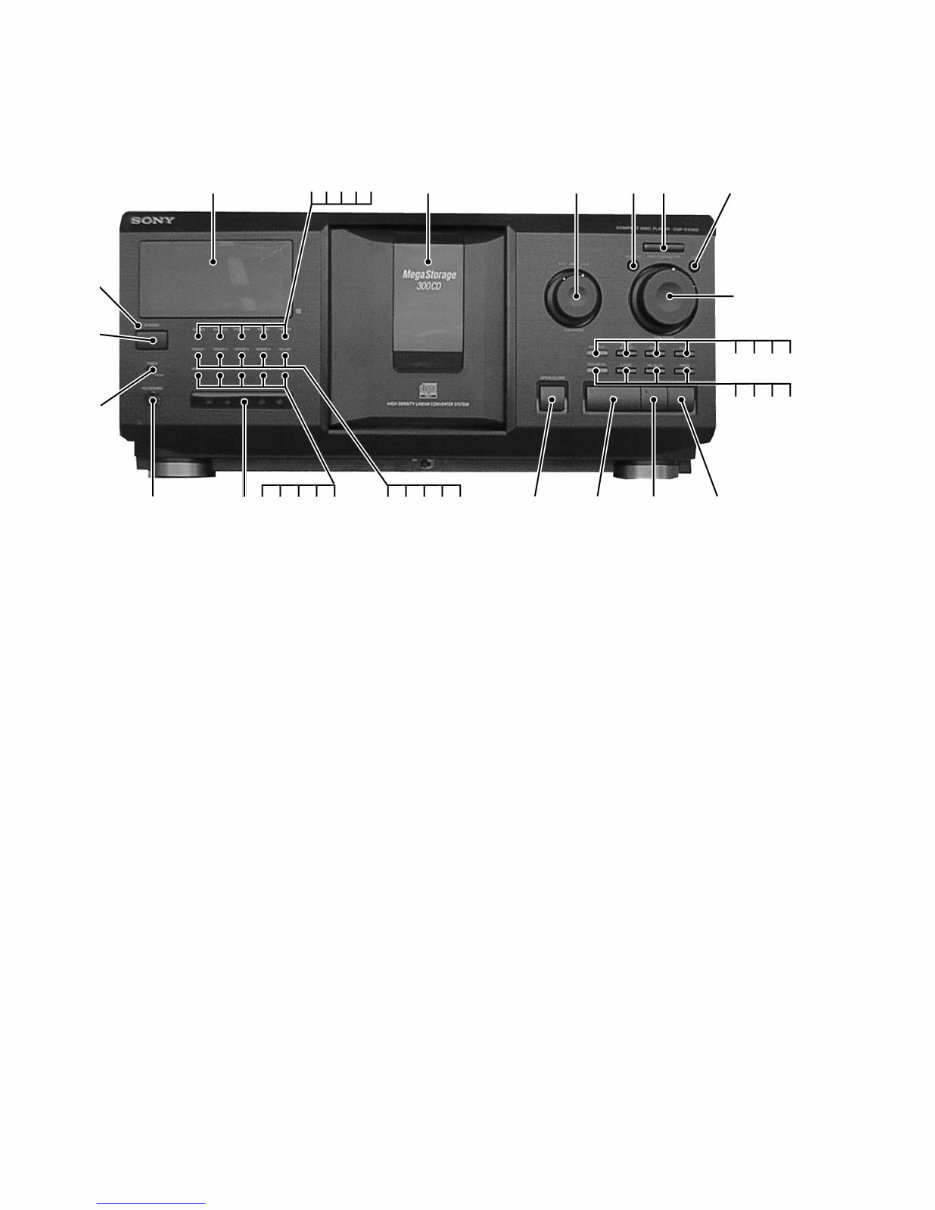
LOCATION OF PARTS AND CONTROLS
1 1/u (power) button
2 STANDBY indicator
3 Display window
4 CONTINUE button
5 SHUFFLE button
6 PROGRAM button
7 REPEAT button
8 TIME/TEXT button
9 Front cover
10 ≠AMS ±/PUSH ENTER knob and button
11 MENU/NO button
12 +100 button
13 YES button
14 DISC/CHARACTER/PUSH ENTER knob and button
15 EASY PLAY button and indicator
16 MEMO/SEARCH button
17 CHECK button
18 CLEAR button
19 MEGA CONTROL button and indicator
20 X-FADE button
SECTION 2
GENERAL
Front Panel
21 NO DELAY button
22 FADER button
23 p (stop)/DISC EJECT button
24 P (pause) button and indicator
25 · (play) button and indicator
26 § OPEN/CLOSE button
27 HIT LIST button and indicator
28 GROUP 4 button and indicator
29 GROUP 3 button and indicator
30 GROUP 2 button and indicator
31 GROUP 1 button and indicator
32 GROUP FILE button
33 GROUP 8 button and indicator
34 GROUP 7 button and indicator
35 GROUP 6 button and indicator
36 GROUP 5 button and indicator
37 IR Repeater window (CDP-CX350)
38 KEYBOARD jack
39 TIMER OFF/PLAY switch
* AMS is abbreviation for Automatic Music Sensor.
3 45678 9 10 11 12
1
2
15 16 17 18
13
14
23 24 25 26 38
39
37
19 20 21 22
31 30 29 28 27 36 35 34 33 32
Photo: CDP-CX350
Downloaded from www.Manualslib.com manuals search engine
– 7 –
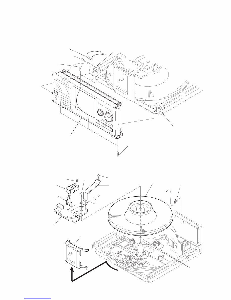
SECTION 3
DISASSEMBLY
Note : Follow the disassembly procedure in the numerical order given.
3-1. FRONT PANEL ASSEMBLY
3-2. TABLE (300) ASSEMBLY
1 Two screws (BVTP 3x8)
3 Two screw (BVTP 3x8)
6 Flat tayp wire(CN701)
2 Three screws (BVTP 3x8)
7 Front panel assembly
5 Remove the claw
4 Remove the claw
LED board
0 Guide (door.T)
1 CD door assembly
3 Two screws (BVTP 3x8)
4 Screw (BVTP 3x8)
5 Bracket (F.W.)
7 Screw (BVTP 3x8)
9 Screw
(BVTP 3x16)
6 LED board
8 Window
!¡ Table (300)assembly
2 Connector (CN)504)
!™ Two washer
Downloaded from www.Manualslib.com manuals search engine
– 8 –
3-3. BASE (DOOR, GEAR) ASSEMBLY
3-4. POP-UP ASSEMBLY
1 Two screws (BVTP 3x8)
2 Cover(front)
4 Guide (Door.B)
6 Bracket (Guide.B)
3 Three screws
(BVTP 3x8)
0 Two screws (BVTP 3x8)
!¡ Three screws (BVTP 3x8)
!™ Base (door.gear) assembly
5 Four screws (BVTP 3x8)
8 Cover(P.T.)
9 Connector (CN508) 7 Two screws (BVTP 3x8)
1 Step screw
3 Pop-up assembly
2 Screw (PTPWH3x6)
Downloaded from www.Manualslib.com manuals search engine
– 9 –
3-5. BACK PANEL ASSEMBLY
3-6. CDM ASSEMBLY
0 Back panel
4 Connector
(CN84)
1 Connector (CN991)
9 Guide (main)
!£ Main board
2 Connector
(CN903)
3 Connector
(CN901)
7 Two screws (BVTP 3x8)
!™ Two screws (BVTP 3x8)
!¡ Two screws (BVTP 3x8) 8 Two screws
(BVTP 3x8)
6 Two screws (BVTP 3x8)
5 Three screws
(BVTP 3x8)
5 Screw
(BVTP 3x8)
8 Power board
4 Screw
6 Two screws
(BVTP 3x8)
2 Two screws
(BVTP 3x8)
9 Three screws
(BVTP 3x8)
1 Three screws
(BVTP 3x8)
3 Three screws
(BVTP 3x8)
7 Four screws
(BVTP 3x8)
0 Bracket(top)
!¡ CDM assembly
Downloaded from www.Manualslib.com manuals search engine
– 10 –
ALL ERASE
This mode is used for clearing information such as the title memo.
Do not execute if information such as the title memo is not to be
erased.
Procedure:
While pressing the CLEAR button with the power OFF, press the
1/u button and turn on the power.
The fluorescent display tube displays “ALL ERASE” and all memo-
ries will be cleared.
AGING MODE
• Mode which repeatedly changes and plays back discs automati-
cally in the unit.
• It will repeat aging as long as no errors occur.
• If an error occurs during aging, it will stop all servos, motors, etc.
instantaneously, display the error number, and stop operations.
However, the stopping conditions differ according to whether the
unit is equipped with the “self-protection function during errors”
described later.
The function serves to maintain the state of the unit when errors
occur.
SECTION 4
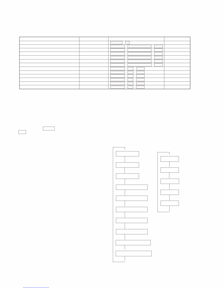
SERVICE MODE
Mode name
ALL ERASE
AGING MODE
LOARDING AGING MODE
TABLE AGING MODE
DOOR POP UP AGING MODE
TABLE LOTATION MODE
TITLE MEMO SHIFT MODE
MODEL NAME DISPLAY
MICROPROCESSOR VERSION DISPLAY
ALL LIT MODE
MECHANISM ADJUSTMENT MODE
SHIPMENT MODE
TITLE MEMO RECORDING CHECK MODE
Power supply state
OFF
ON
ON
ON
ON
ON
ON
ON
ON
ON
ON
ON
ON
Button operation
CLEAR + 1
GROUP 1 + § OPEN/CLOSE + +100
GROUP 2 + § OPEN/CLOSE + +100
GROUP 3 + § OPEN/CLOSE + +100
GROUP 4 + § OPEN/CLOSE + +100
GROUP 5 + § OPEN/CLOSE + +100
GROUP 7 + § OPEN/CLOSE + +100
GROUP 1 + · + +100
GROUP 2 + · + +100
GROUP 3 + · + +100
GROUP 4 + · + +100
GROUP 5 + · + +100
GROUP 6 + · + +100
Remarks
Note 1
Used in adjustment
Note 1
Note 1
Note 1
Do not execute unless with a proper reason, otherwise the memory of the title memo recorded by the customer will be erased.
The title memo recording check mode is not required for servicing. Do not execute.
SPECIAL FUNCTION
This unit is provided with several service modes.
Details are shown in the following table.
1. Disc change
2. Load in
3. TOC read
4. Access of last track
5. 3 second playback
6. Access of first track
7. 3 second playback
8. Load out
9. FRONT COVER open
10. FRONT COVER close
1. No. 60
2. No. 240
3. No. 180
4. No. 300
5. No. 120
Sequence of Aging Mode
$
$
$
$
$
$
$
$
$
Order of Disc Change
(1 cycle takes 3 minutes)
$
$
$
$
$
$
$
$
Downloaded from www.Manualslib.com manuals search engine
You're Reading a Preview
What's Included?
Fast Download Speeds
Online & Offline Access
Access PDF Contents & Bookmarks
Full Search Facility
Print one or all pages of your manual
$31.99
Viewed 59 Times Today


Secure transaction
What's Included?
Fast Download Speeds
Online & Offline Access
Access PDF Contents & Bookmarks
Full Search Facility
Print one or all pages of your manual
$31.99
This service manual for the Sony CDP-CX300/CX350/CX691 Compact Disc Player provides essential technical information for servicing and repair. It includes detailed sections on disassembly, service mode, test mode, adjustments, diagrams, exploded views, and an electrical parts list. The manual spans 60 pages and is available in English. It is compatible with both Windows and MAC platforms.


