

SERVICE MANUAL
D&M Holdings Inc.
Copyright 2013 D&M Holdings Inc. All rights reserved.
WARNING: Violators will be prosecuted to the maximum extent possible.
MODEL JP E3 E2 EK EA E1 E1K E1C
DN-SC2900 P P P
DIGITAL CONTROLLER AND MEDIA PLAYER
Ver. 6
S0658-1V06DM/DG1304
• Some illustrations using in this service manual are slightly different from the actual set.
• Please use this service manual with referring to the operating instructions without fail.
• For purposes of improvement, specifications and design are subject to change without notice.
Please refer to the
MODIFICATION NOTICE.

2
CONTENTS
SAFETY PRECAUTIONS ..........................................................3
NOTE FOR SCHEMATIC DIAGRAM.........................................4
NOTE FOR PARTS LIST ...........................................................4
TECHNICAL SPECIFICATIONS ................................................5
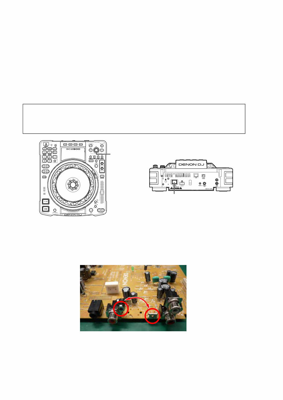
DIMENSION ...............................................................................5
CAUTION IN SERVICING..........................................................6
Initializing DIGITAL CONTROLLER AND MEDIA
PLAYER(Factory Adjust) ...........................................................6
Upgrading the version of the firmware ......................................6
About the POWER PCB UNIT ASSY(8U-110117) ....................6
Service Jigs ...............................................................................6
DISASSEMBLY ..........................................................................7
1. TOP SUB ASSY ....................................................................9
2. PWB USB ............................................................................ 11
3. PWB MAIN ..........................................................................12
4. PWB POWER......................................................................13
5. CD MECHA ASSY ...............................................................14
6. JOG ASSY...........................................................................15
7. PWB TOP FRONT...............................................................16
8. PWB FADER .......................................................................17
9. PWB TOP REAR .................................................................19
10. ...................................................................................... PWB
VFD .........................................................................................21
DIAGNOSTICS OF OPTICAL PICKUP AND REPLACING
MECH UNIT..............................................................................22
1. Mech. unit replacing ............................................................22
2. Laser drive current (Iop) measurement method ..................22
3. Laser current measurement ................................................22
SPECIAL MODE ......................................................................23
Function summary...................................................................23
1. SERVICE MODE .................................................................24
2. Checking the operations of the functions (Function CHK) ..24
3. Checking the operations of the CD drive (CD Drive CHK) ..28
4. Checking the operations of the switches (SW Check) ........32
5. Checking the operation of the panel (Panel CHK) ..............34
6. JOG pulse check mode and Touch sensor check mode (JOG
CHK) .......................................................................................35
7. System information mode (SYSTEM INFO) ........................36
8. Version upgrade procedure of firmware ..............................36
WHEN THE MICROPROCESSOR IS REPLACED WITH A
NEW ONE ................................................................................37
PROCEDURE FOR UPGRADING THE VERSION OF THE
FIRMWARE ..............................................................................37
1. Procedure for upgrading U1101 ..........................................37
2. Procedure for upgrading U100 ............................................38
TROUBLE SHOOTING ............................................................39
MEASURING METHOD AND WAVEFORMS .........................52
WAVEFORMS .........................................................................53
BLOCK DIAGRAM...................................................................54
POWER BLOCK DIAGRAM ....................................................55
LEVEL DIAGRAM....................................................................56
PRINTED WIRING BOARDS...................................................57
POWER...................................................................................57
MAIN ......................................................................................58
CD SLOT ................................................................................58
SOURCE SELECT .................................................................58
VFD ........................................................................................58
USB ........................................................................................58
PANEL1 ..................................................................................59
PANEL2 ..................................................................................61
SLIDE VR ...............................................................................61
RING LED ...............................................................................62
PHOTO SENSOR ...................................................................62
WIRING DIAGRAM ..................................................................63
SCHEMATIC DIAGRAMS (1/7) ...............................................64
POWER UNIT (1/2) .................................................................64
POWER UNIT (2/2) .................................................................65
PANEL1 UNIT .........................................................................66
PANEL2 UNIT .........................................................................66
VFD UNIT................................................................................66
SOURCE SELECT UNIT.........................................................66
SLIDE VR UNIT.......................................................................66
USB UNIT................................................................................66
MAIN UNIT (1/3)......................................................................67
MAIN UNIT (2/3)......................................................................68
MAIN UNIT (3/3)......................................................................69
RING LED UNIT / PHOTO SENSOR UNIT.............................70
EXPLODED VIEW....................................................................71
PARTS LIST OF EXPLODED VIEW........................................72
PACKING VIEW .......................................................................75
PARTS LIST OF PACKING & ACCESSORIES.......................75
SEMICONDUCTORS ...............................................................77
1. IC's ......................................................................................77
2. VF DISPLAY ........................................................................92
PARTS LIST OF P.C.B. UNIT ..................................................97
PANEL PCB UNIT ASSY .........................................................97
MAIN PCB UNIT ASSY .........................................................106
RING LED PCB UNIT ASSY ................................................. 112

3
SAFETY PRECAUTIONS
The following items should be checked for continued protection of the customer and the service technician.
LEAKAGE CURRENT CHECK
Before returning the set to the customer, be sure to carry out either (1) a leakage current check or (2) a line to chassis
resistance check. If the leakage current exceeds 0.5 milliamps, or if the resistance from chassis to either side of the
power cord is less than 460 kohms, the set is defective.
Be sure to test for leakage current with the AC plug in both polarities, in addition, when the set's power is in each state (on,
off and standby mode), if applicable.
CAUTION Please heed the following cautions and instructions during servicing and
inspection.
◎ Heed the cautions!
Cautions which are delicate in particular for servicing
are labeled on the cabinets, the parts and the chassis,
etc. Be sure to heed these cautions and the cautions
described in the handling instructions.
◎ Cautions concerning electric shock!
(1) An AC voltage is impressed on this set, so if
you touch internal metal parts when the set is
energized, you may get an electric shock. Avoid
getting an electric shock, by using an isolating
transformer and wearing gloves when servicing
while the set is energized, or by unplugging the
power cord when replacing parts, for example.
(2) There are high voltage parts inside. Handle with
extra care when the set is energized.
◎ Caution concerning disassembly and
assembly!
Through great care is taken when parts were
manufactured from sheet metal, there may be burrs
on the edges of parts. The burrs could cause injury if
fingers are moved across them in some rare cases.
Wear gloves to protect your hands.
◎ Use only designated parts!
The set's parts have specific safety properties (fire
resistance, voltage resistance, etc.). Be sure to use
parts which have the same properties for replacement.
The burrs have the same properties. In particular, for
the important safety parts that are indicated by the z
mark on schematic diagrams and parts lists, be sure to
use the designated parts.
◎ Be sure to mount parts and arrange the wires
as they were originally placed!
For safety seasons, some parts use tapes, tubes or
other insulating materials, and some parts are mounted
away from the surface of printed circuit boards.
Care is also taken with the positions of the wires by
arranging them and using clamps to keep them away
from heating and high voltage parts, so be sure to set
everything back as it was originally placed.
◎ Make a safety check after servicing!
Check that all screws, parts and wires removed or
disconnected when servicing have been put back in
their original positions, check that no serviced parts
have deteriorate the area around. Then make an
insulation check on the external metal connectors and
between the blades of the power plug, and otherwise
check that safety is ensured.
(Insulation check procedure)
Unplug the power cord from the power outlet,
disconnect the antenna, plugs, etc., and on the power.
Using a 500V insulation resistance tester, check that
the insulation resistance value between the inplug and
the externally exposed metal parts (antenna terminal,
headphones terminal, input terminal, etc.) is 1MΩ or
greater. If it is less, the set must be inspected and
repaired.
Many of the electric and the structural parts used in
the set have special safety properties. In most cases
these properties are difficult to distinguish by sight, and
the use of replacement parts with higher ratings (rated
power and withstand voltage) does not necessarily
guarantee that safety performance will be preserved.
Parts with safety properties are indicated as shown
below on the wiring diagrams and the parts list in this
service manual. Be sure to replace them with the parts
which have the designated part number.
(1) Schematic diagrams.......Indicated by the z mark.
(2) Parts lists.......Indicated by the z mark.
The use of parts other than the
designated parts could cause electric
shocks, fires or other dangerous
situations.
CAUTION Concerning important safety
parts

4
NOTE FOR SCHEMATIC DIAGRAM
WARNING:
Parts indicated by the z mark have critical characteristics. Use ONLY replacement parts recommended by the manufacturer.
CAUTION:
Before returning the set to the customer, be sure to carry out either (1) a leakage current check or (2) a line to chassis resistance check. If
the leakage current exceeds 0.5 milliamps, or if the resistance from chassis to either side of the power cord is less than 460 kohms, the set
is defective.
WARNING:
DO NOT return the set to the customer unless the problem is identified and remedied.
NOTICE:
ALL RESISTANCE VALUES IN OHM. k=1,000 OHM / M=1,000,000 OHM
ALL CAPACITANCE VALUES ARE EXPRESSED IN MICRO FARAD, UNLESS OTHERWISE INDICATED. P INDICATES MICRO-MICRO
FARAD. EACH VOLTAGE AND CURRENT ARE MEASURED AT NO SIGNAL INPUT CONDITION. CIRCUIT AND PARTS ARE SUBJECT
TO CHANGE WITHOUT PRIOR NOTICE.
Parts indicated by "nsp" on this table cannot be supplied.
When ordering a part, make a clear distinction between "1" and "I" (i) to avoid mis-supplying.
A part ordered without specifying its part number can not be supplied.
General-purpose Carbon Chip Resistors are not included are not included in the P.W.Board parts list.
(Refer to the Schematic Diagram for those parts.)
Parts indicated by the z mark have critical characteristics. Use ONLY replacement parts recommended by the manufacturer.
General-purpose Carbon Film Resistor in the P.W.Board parts list. (Refer to the Schematic Diagram for those parts.)
Part indicated by "★" mark is not illustrated in the exploded view.
WARNING:
1.
2.
3.
4.
5.
6.
NOTE FOR PARTS LIST
5
TECHNICAL SPECIFICATIONS
n Audio
(0 dBu =0.775 Vrms, 0 dBV =1 Vrms)
Quantization: 32 bit (internal DSP process)
Sampling frequency: 44.1 kHz (at normal pitch)
Total harmonic distortion: 0.05 % or less
Signal to noise ratio: 106 dB or more (A-weighted)
Head room: 6 dB
Channel separation: 100 dB or more
Frequency response: 20 – 20 kHz, ±0.5 dB
・Analog output
Output level: 2.0 Vrms
・Digital output
Output level: 0.5 Vp-p 75Ω
n Functions
Variable pitch: ±6 % (0.02 % pitch)
±10 % (0.05 % pitch)
±16% (0.05 % pitch)
±100 % (1.0 % pitch)
Pitch bend: Pitch range ±6 % – ±16 % : ±32 %
Pitch range ±100 % : –99 % – +100 %
Search precision: 1/75 sec.
Folder search: 9 layers (including root folder)
n General
USB MIDI input/output: IN : 1 ch, OUT : 1 ch MIDI 1.0, USB B
Power supply:d
U.S.A. and Canada models:
AC 120 V, 60 Hz
European, U.K. and Asia/
Pacific models:
Japan model:
AC 230 V, 50 Hz
AC100V, 50/60 Hz f
Power consumption: 30 W
Operational temperature: +5 °C – +35 °C
Operational humidity: 25 % – 85 %
Storage temperature: –20 °C – +60 °C
326
123.8
366
DIMENSION
6
Initializing DIGITAL CONTROLLER AND MEDIA PLAYER(Factory Adjust)
DIGITAL CONTROLLER AND MEDIA PLAYER initialization should be performed when CD MECHA UNIT was replaced.
(Refer to "3.5. Factory adjustment (Factory Adjust)"(page 30))
1. Turn on the power while pressing the SEL. knob and the HOT LIST button simultaneously
2. Turn the SEL. knob to select "CD Drive CHK" from the "Factory Adjust" mode's top menu.
3. Press the SEL. knob to start adjusting without a disc.
4. The first half of the process is completed in approximately 10 seconds, and "Insert Disc" appears on the VFD dot
display section.
5. After loading the disc, the latter half of the process is performed.
6. The latter half of the process is completed in approximately 10 seconds.
Once the microcomputer has been initialized, "Complete!" appears on the VFD dot display section.
7. To exit the "Factory Adjust" mode, press the POWER ON/OFF button to turn the power off.
Upgrading the version of the firmware
When the panel µcom (U100) or the Touch µcom (U1101) is replaced, update the panel µcom.
(Refer to "PROCEDURE FOR UPGRADING THE VERSION OF THE FIRMWARE"(page 37)
About the POWER PCB UNIT ASSY(8U-110117)
To remove the POWER PCB UNIT ASSY(8U-110117) out of the chassis for check, connect GND terminals of B2002 and
K2000 before checking it.
Service Jigs
When you initialize this unit, you can use the following JIG (Exclusive disk).
Please order it from Denon Official Service Distributor in your region if necessary.
Exclusive disk : TCD-792A (made by ALMEDIO)
NOTE: • If step 6 fails, start over from step 1.
• All user settings will be lost and the factory setting will be recovered after the set is initialized.
So make sure to note down your setting beforehand for restoring after the initialization.
• Always use a disc dedicated for initialization (ALMEDIO's TCD-792A).
SEL.
[ TOP ] [ REAR ]
POWER ON/OFF
CAUTION IN SERVICING
7
DISASSEMBLY
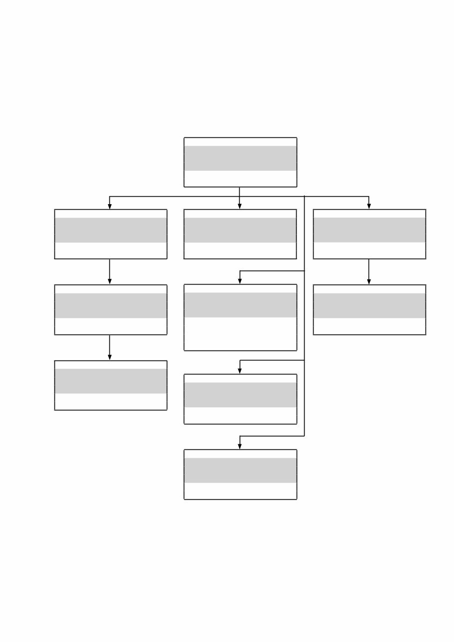
• Disassemble in order of the arrow in the following figure.
• In the case of the re-assembling, assemble it in order of the reverse of the following flow.
• In the case of the reassembling, observe "Caution concerning disassembly and assembly!".
• If wire bundles are untied or moved to perform adjustment or replace parts etc., be sure to rearrange them neatly as
they were originally bundled or placed afterward.
Otherwise, incorrect arrangement can be a cause of noise generation.
TOP SUB ASSY
Refer to "DISASSEMBLY
1.TOP SUB ASSY"
and "EXPLODED VIEW"
TOP CASE SUB ASSY
(Ref. No. of EXPLODED VIEW : F)
PWB USB
Refer to "DISASSEMBLY
2. PWB USB"
and "EXPLODED VIEW"
USB UNIT
(Ref. No. of EXPLODED VIEW : B-7)
PWB MAIN
Refer to "DISASSEMBLY
3. PWB MAIN"
and "EXPLODED VIEW"
MAIN PCB UNIT ASSY
(Ref. No. of EXPLODED VIEW : C)
PWB POWER
Refer to "DISASSEMBLY
4. PWB POWER"
and "EXPLODED VIEW"
POWER PCB UNIT ASSY
(Ref. No. of EXPLODED VIEW : A)
CD MECHA ASSY
Refer to "DISASSEMBLY
5. CD MECHA ASSY"
and "EXPLODED VIEW"
TD-S208-PR4
(Ref. No. of EXPLODED VIEW : 4)
PWB TOP REAR
Refer to "DISASSEMBLY
9. PWB TOP REAR"
and "EXPLODED VIEW"
PANEL1 UNIT
(Ref. No. of EXPLODED VIEW : B-1)
PWB VFD
Refer to "DISASSEMBLY
10. PWB VFD"
and "EXPLODED VIEW"
VFD UNIT
(Ref. No. of EXPLODED VIEW : B-4)
PWB FADER
Refer to "DISASSEMBLY
8. PWB FADER"
and "EXPLODED VIEW"
SLIDE VR UNIT
(Ref. No. of EXPLODED VIEW : B-6)
PWB TOP FRONT
Refer to "DISASSEMBLY
7. PWB TOP FRONT"
and "EXPLODED VIEW"
PANEL2 UNIT
(Ref. No. of EXPLODED VIEW : B-2)
JOG ASSY
Refer to "DISASSEMBLY
6. JOG ASSY"
and "EXPLODED VIEW"
JOG ASSY
(Ref. No. of EXPLODED VIEW : G)
RING LED UNIT
(Ref. No. of EXPLODED VIEW : D)
8
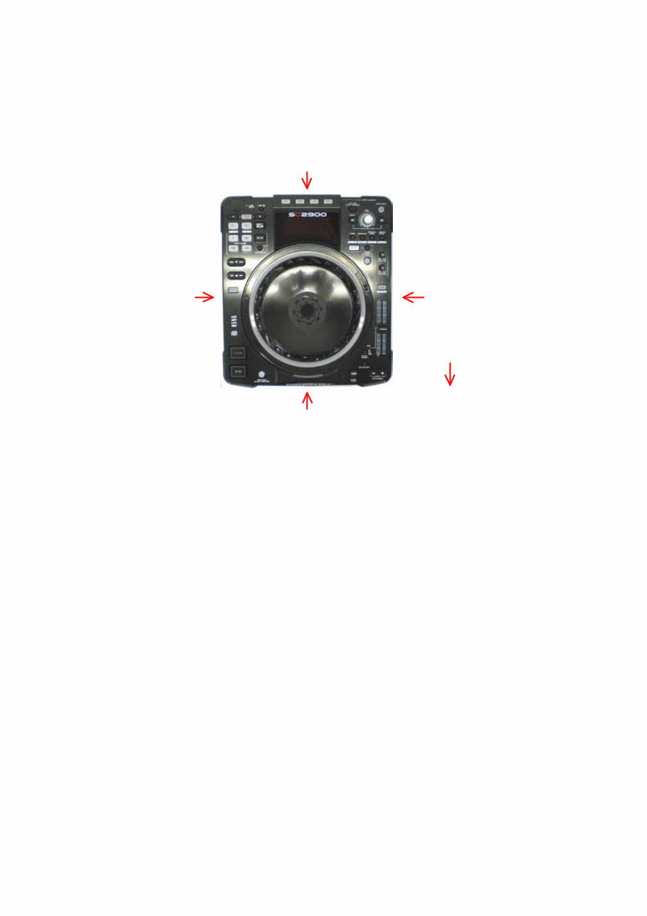
About the photos used for "descriptions of the DISASSEMBLY" section
• The shooting direction of each photograph used herein is indicated on the left side of the respective photograph as
"Shooting direction: ***". (*** : A,B,C,D)
• Refer to the diagram below about the shooting direction of each photograph.
• Photographs with no shooting direction indicated were taken from the top of the set.
The viewpoint of each photograph
(Shooting direction)
[View from the top]
Front side
Shooting direction: B
Shooting direction: D Shooting direction: C
Shooting direction: A
9
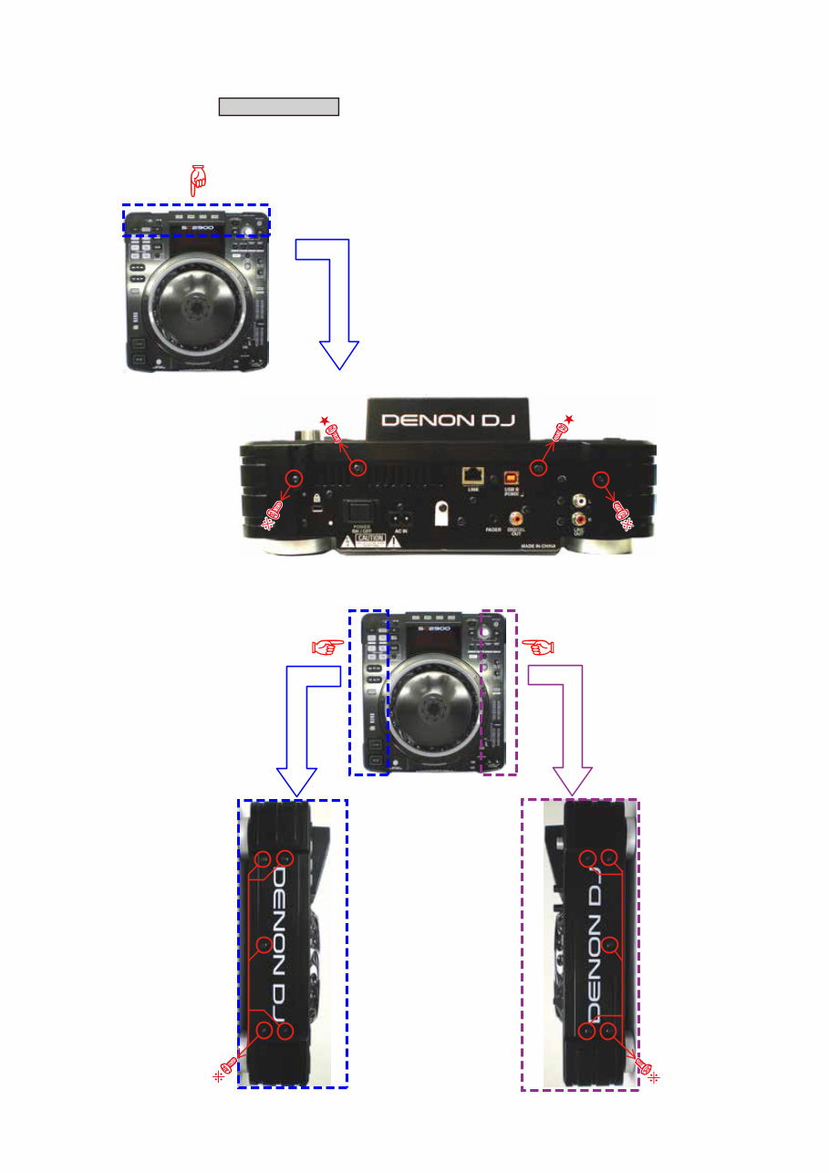
1. TOP SUB ASSY
(1) Remove the screws.
TOP SUB ASSY Proceeding :
Shooting direction: B
Shooting direction: D Shooting direction: C
10
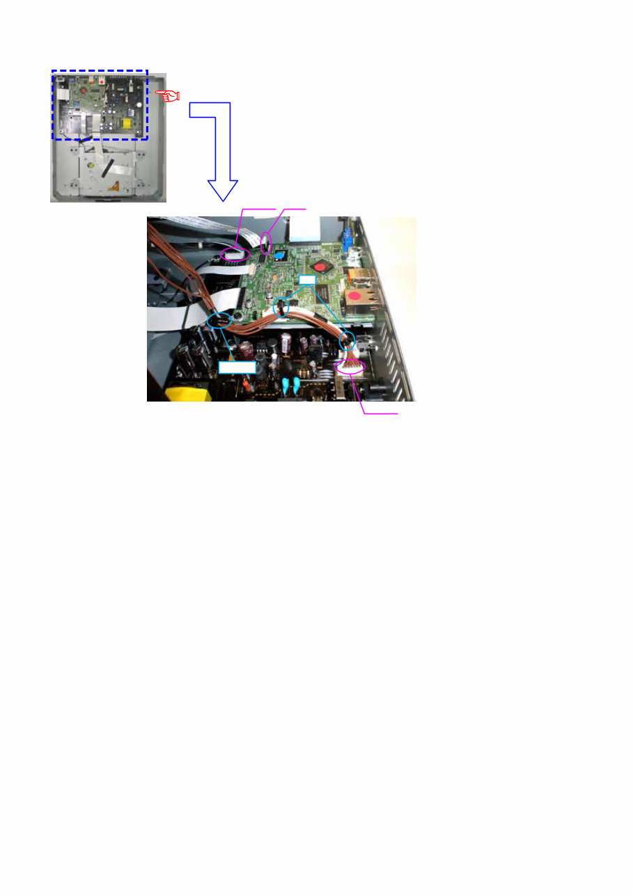
(2) Cut the wire clamp bands, then disconnect the connector wires and FFC.
Shooting direction: D
N0081
FFC N282
Loosen
cut
You're Reading a Preview
What's Included?
 Lifetime Access
Fast Download Speeds
Online & Offline Access
Access PDF Contents & Bookmarks
Full Search Facility
Print one or all pages of your manual
$36.99
Denon DN SC2900 Service Manual & Repair Guide
Viewed 54 Times Today

What's Included?
Lifetime Access
Fast Download Speeds
Online & Offline Access
Access PDF Contents & Bookmarks
Full Search Facility
Print one or all pages of your manual
$36.99

Secure transaction
What's Included?
Lifetime Access
Fast Download Speeds
Online & Offline Access
Access PDF Contents & Bookmarks
Full Search Facility
Print one or all pages of your manual
Description
This service and repair manual is an essential resource for anyone looking to troubleshoot and repair the Denon DN SC2900 USB Midi Controller. Whether you are a professional technician or a DIY enthusiast, this manual provides detailed insights into the device's inner workings.
- Safety & Precautions
- Product Specifications
- Service Mode
- Troubleshooting
- Disassembly & Reassembly
- Semiconductors
- Printed Wiring Boards
- Block Diagram
- Level Diagram
- Wiring Diagrams
- Schematic Diagrams
- Exploded Views
- Replacement Parts list
This comprehensive manual is richly illustrated with pictures and step-by-step instructions, ensuring that you can effectively service and repair the device. It is the official service and repair manual, providing high-resolution pages for optimal print quality.
With instant access upon payment, there are no shipping fees or waiting for postal delivery, allowing you to commence repairs promptly.
Specifications:
- Language: English
- Format: PDF
- Pages: 114


