

Denon DCD-CX3 Service Manual & Repair Guide
What's Included?
Fast Download Speeds
Online & Offline Access
Access PDF Contents & Bookmarks
Full Search Facility
Print one or all pages of your manual
Denon Brand Company, D&M Holdings lnc.
e
●
For purposes of improvement, specifications and
design are subject to change without notice.
●
Please use this service manual with referring to the
operating instructions without fail.
●
Some illustrations using in this service manual are
slightly different from the actual set.
注 意
サービスをおこなう前に、このサービスマニュアルを
必ずお読みください。本機は、火災、感電、けがなど
に対する安全性を確保するために、さまざまな配慮を
おこなっており、また法的には「電気用品安全法」に
もとづき、所定の許可を得て製造されております。
従ってサービスをおこなう際は、これらの安全性が維
持されるよう、このサービスマニュアルに記載されて
いる注意事項を必ずお守りください。
●
本機の仕様は性能改良のため、予告なく変更すること
があります。
●
補修用性能部品の保有期間は、製造打切後 8 年です。
●
修理の際は、必ず取扱説明書を参照の上、作業を行っ
てください。
●
本文中に使用しているイラストは、説明の都合上現物
と多少異なる場合があります。
S-1184 V.05 DE/CDM 0803
SERVICE MANUAL
SUPER AUDIO CD PLAYER
MODEL JP E3 E2 EK E2A E1C E1K EUT
DCD-CX3
Ver. 5
Please refer to the
MODIFICATION NOTICE.
g
2
DCD-CX3
Please heed the points listed below during servicing and inspection.
◎ Heed the cautions!
Spots requiring particular attention when servicing, such
as the cabinet, parts, chassis, etc., have cautions indicated
on labels or seals. Be sure to heed these cautions and the
cautions indicated in the handling instructions.
◎ Caution concerning electric shock!
(1) An AC voltage is impressed on this set, so touching in-
ternal metal parts when the set is energized could
cause electric shock. Take care to avoid electric shock,
by for example using an isolating transformer and
gloves when servicing while the set is energized, un-
plugging the power cord when replacing parts, etc.
(2)There are high voltage parts inside. Handle with extra
care when the set is energized.
◎ Caution concerning disassembly and
assembly!
Though great care is taken when manufacturing parts from
sheet metal, there may in some rare cases be burrs on the
edges of parts which could cause injury if fingers are
moved across them. Use gloves to protect your hands.
◎ Only use designated parts!
The set's parts have specific safety properties (fire resis-
tance, voltage resistance, etc.). For replacement parts, be
sure to use parts which have the same properties. In par-
ticular, for the important safety parts that are marked z on
wiring diagrams and parts lists, be sure to use the desig-
nated parts.
◎ Be sure to mount parts and arrange
the wires as they were originally!
For safety reasons, some parts use tape, tubes or other in-
sulating materials, and some parts are mounted away from
the surface of printed circuit boards. Care is also taken with
the positions of the wires inside and clamps are used to
keep wires away from heating and high voltage parts, so
be sure to set everything back as it was originally.
◎ Inspect for safety after servicing!
Check that all screws, parts and wires removed or discon-
nected for servicing have been put back in their original po-
sitions, inspect that no parts around the area that has been
serviced have been negatively affected, conduct an insu-
lation check on the external metal connectors and between
the blades of the power plug, and otherwise check that
safety is ensured.
(Insulation check procedure)
Unplug the power cord from the power outlet, disconnect
the antenna, plugs, etc., and turn the power switch on. Us-
ing a 500V insulation resistance tester, check that the in-
sulation resistance between the terminals of the power
plug and the externally exposed metal parts (antenna ter-
minal, headphones terminal, microphone terminal, input
terminal, etc.) is 1MΩ or greater. If it is less, the set must
be inspected and repaired.
Concerning important safety
parts
Many of the electric and structural parts used in the set
have special safety properties. In most cases these prop-
erties are difficult to distinguish by sight, and using re-
placement parts with higher ratings (rated power and
withstand voltage) does not necessarily guarantee that
safety performance will be preserved. Parts with safety
properties are indicated as shown below on the wiring dia-
grams and parts lists is this service manual. Be sure to re-
place them with parts with the designated part number.
(1) Schematic diagrams ... Indicated by the z mark.
(2) Parts lists ... Indicated by the z mark.
Using parts other than the designated
parts could result in electric shock, fires or
other dangerous situations.
SAFETY PRECAUTIONS
The following check should be performed for the continued protection of the customer and service technician.
LEAKAGE CURRENT CHECK
Before returning the unit to the customer, make sure you make either (1) a leakage current check or (2) a line to chassis
resistance check. If the leakage current exceeds 0.5 milliamps, or if the resistance from chassis to either side of the
power cord is less than 460 kohms, the unit is defective.
LASER RADIATION
Caution - Class 1M visible and invisible laser radiation when open.
Do not view directly with optical instruments.
CAUTION
CAUTION
s

3
DCD-CX3
サービス、点検時にはつぎのことにご注意願います。
◎注意事項をお守りください!
サービスのとき特に注意を必要とする個所については
キャビネット、部品、シャーシなどにラベルや捺印で注意
事項を表示しています。これらの注意書きおよび取扱説明
書などの注意事項を必ずお守りください。
◎感電に注意!
(1) このセットは、交流電圧が印加されていますので通電
時に内部金属部に触れると感電することがあります。
従って通電サービス時には、絶縁トランスの使用や手
袋の着用、部品交換には、電源プラグを抜くなどして
感電にご注意ください。
(2) 内部には高電圧の部分がありますので、通電時の取扱
には十分ご注意ください。
◎分解、組み立て作業時のご注意!
板金部品の端面の『バリ』は、部品製造時に充分管理をし
ておりますが、板金端面は鋭利となっている箇所が有りま
すので、部品端面に触れたまま指を動かすとまれに怪我を
する場合がありますので十分注意して作業して下さい。手
の保護のために手袋を着用してください。
◎指定部品の使用!
セットの部品は難燃性や耐電圧など安全上の特性を持っ
たものとなっています。従って交換部品は、使用されてい
たものと同じ特性の部品を使用してください。特に配線
図、部品表に z 印で指定されている安全上重要な部品は
必ず指定のものをご使用ください。
◎部品の取付けや配線の引きまわしは、
元どおりに!
安全上、テープやチューブなどの絶縁材料を使用したり、
プリント基板から浮かして取付けた部品があります。また
内部配線は引きまわしやクランパーによって発熱部品や
高圧部品に接近しないように配慮されていますので、これ
らは必ず元どおりにしてください。
◎サービス後は安全点検を!
サービスのために取り外したねじ、部品、配線などが元ど
おりになっているか、またサービスした個所の周辺を劣化
させてしまったところがないかなどを点検し、外部金属端
子部と、電源プラグの刃の間の絶縁チェックをおこなうな
ど、安全性が確保されていることを確認してください。
(絶縁チェックの方法)
電源コンセントから電源プラグを抜き、アンテナやプラグ
などを外し、電源スイッチを入れます。500V 絶縁抵抗計
を用いて、電源プラグのそれぞれの端子と外部露出金属部
[アンテナ端子、ヘッドホン端子、マイク端子、入力端子
など]との間で、絶縁抵抗値が1 MΩ 以上であることを
確認してください。この値以下のときはセットの点検修理
が必要です。
安全上重要な部品について
本機に使用している多くの電気部品、および機構部品は安
全上、特別な特性を持っています。この特性はほとんどの
場合、外観では判別つきにくく、またもとの部品より高い
定格(定格電力、耐圧)を持ったものを使用しても安全性
が維持されるとは、限りません。安全上の特性を持った部
品は、このサービスマニュアルの配線図、部品表につぎの
ように表示していますので必ず指定されている部品番号
のものを使用願います。
(1) 配線図… z マークで表示しています。
(2) 部品表… z マークで表示しています。
指定された部品と異なるものを使用した場
合には、感電、火災などの危険を生じる恐
れがあります。
注 意
注 意
4
DCD-CX3
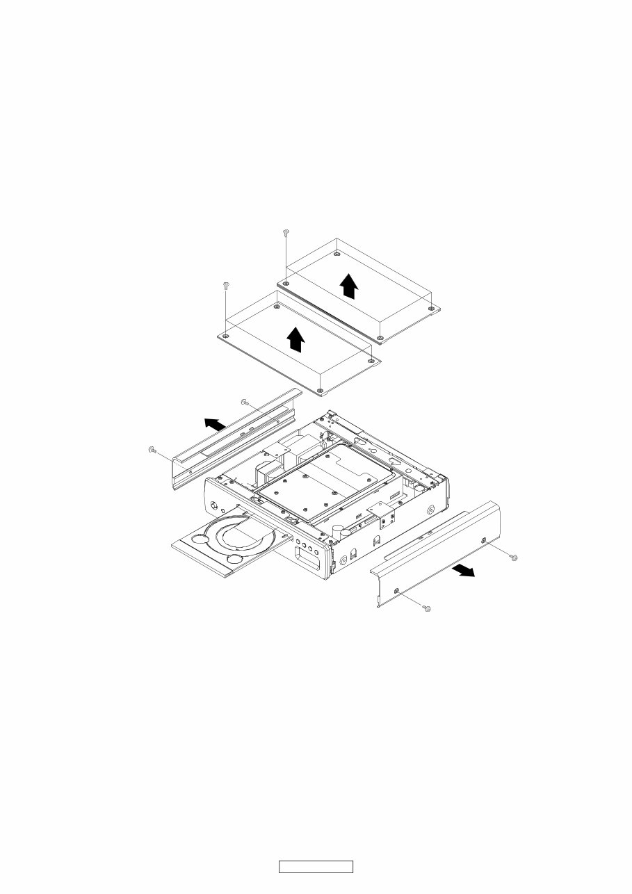
各部のはずしかた
※ セットを分解するときは、トレイを開け、電源 OFF 状
態にしてください。
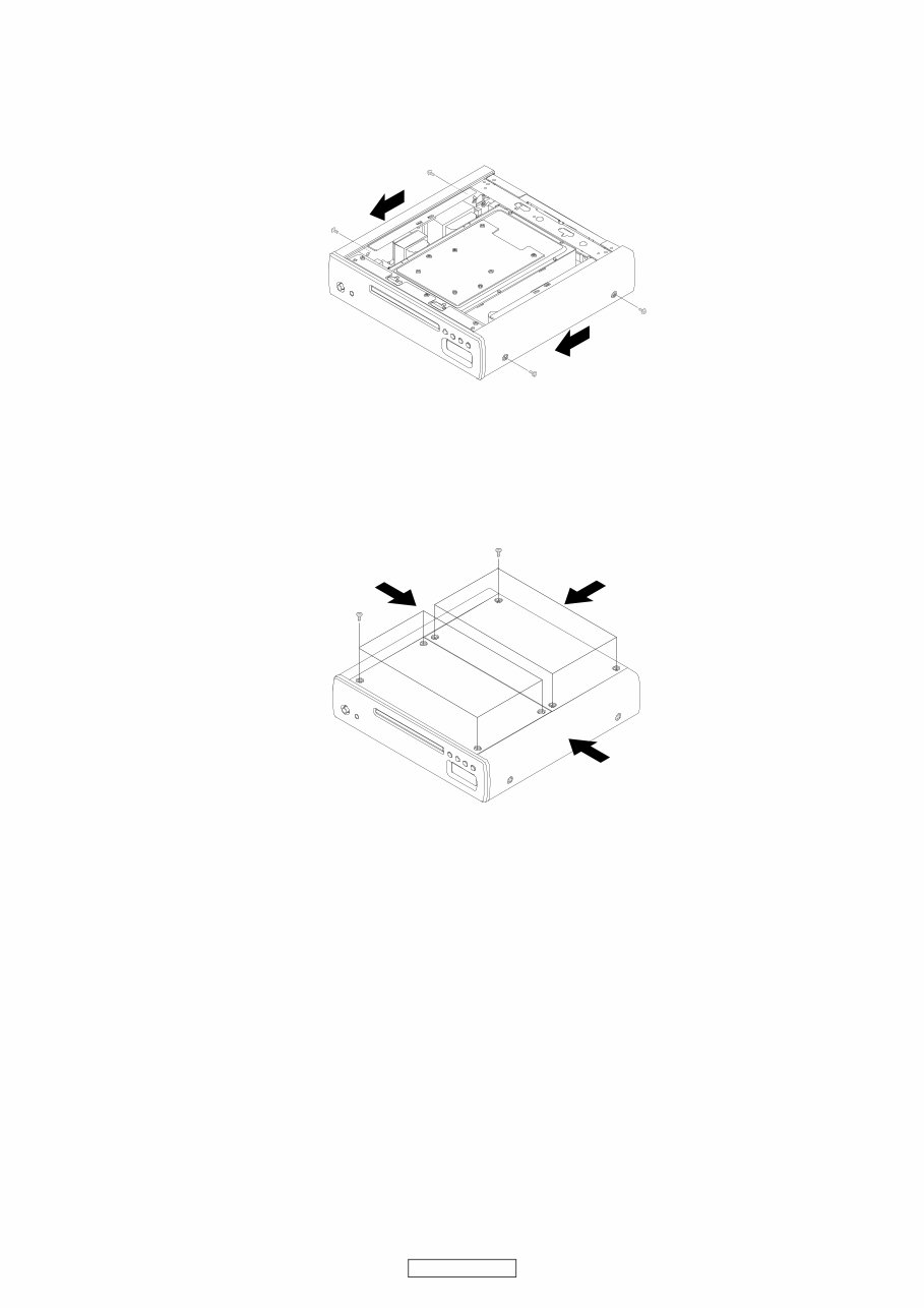
1. トップパネル、サイドパネルのはずしかた
(1) トップパネルを取り付けているネジ 8 本をはずしま
す。
(2) トップパネルを矢印の方向にはずします。
(3) サイドパネルを取り付けているネジ 4 本をはずしま
す。
(4) サイドパネルを矢印の方向にはずします。
DISASSEMBLY
※ When taking the set apart, open the tray and turn the
power "OFF".
1. Top Panel and Side Panel
(1) Remove 8 top screws, then detach Top Panel.
(2) Remove 4 side screws, then detach Side Panel.
5
DCD-CX3
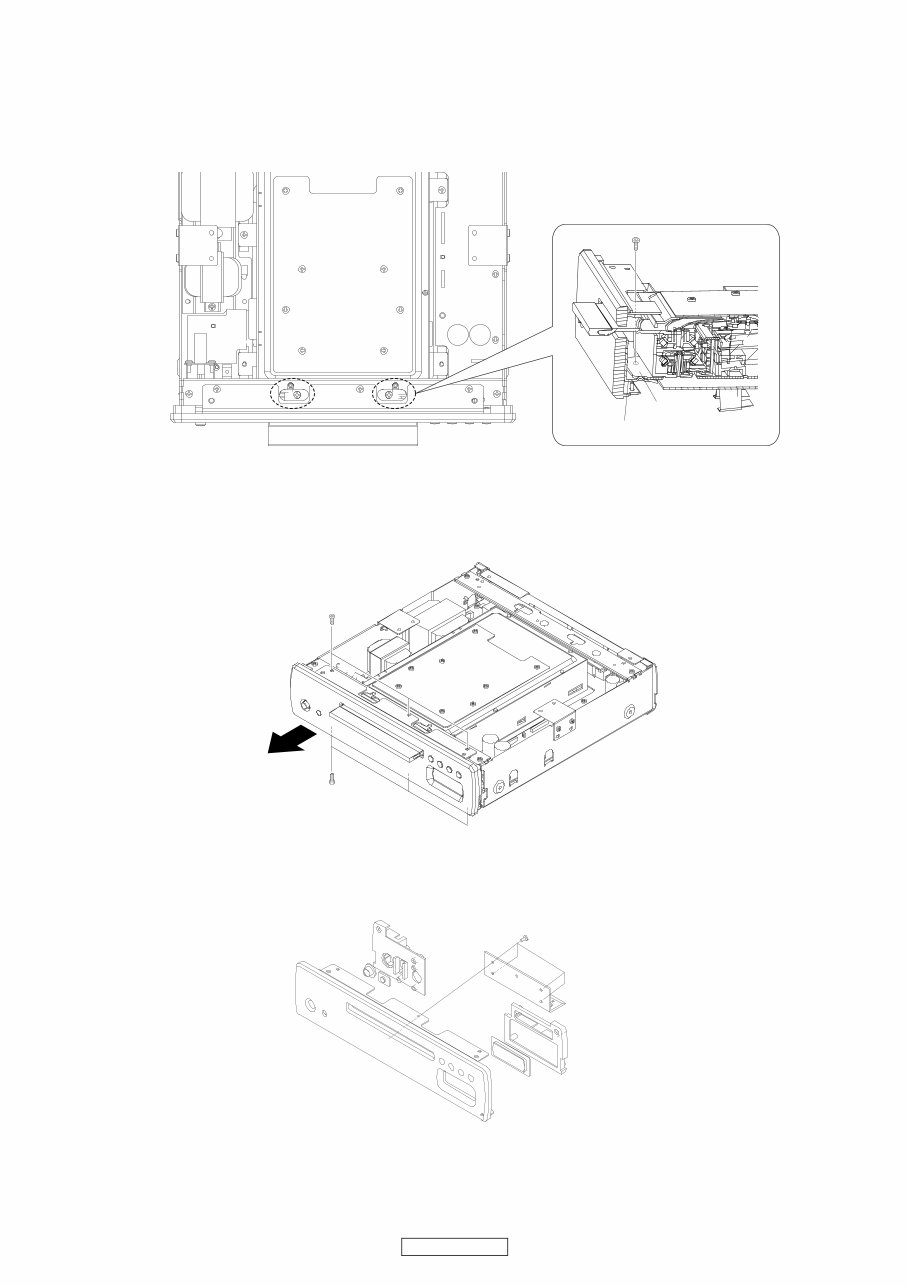
2. フロントパネルのはずしかた
(1) フロントパネル上部の切り欠き部(2ヶ所)からネジが
見える位置まで、トレイを押し込みます。(fig. A 参照)
(2) ネジ2本をはずします。(fig.B 参照)
(3) フロントパネルを取り付けている、上部のネジ 3 本と
底部のネジ 3 本をはずします。
(4) フロントパネルを矢印の方向にはずします。
※ フロントパネルを廃棄する場合は、下図のように分解し
てください。
2. Front Panel Ass’y
(1) Press the tray in to the position at which screws can be
seen through the 2 cuts in the top of the Front Panel.
(Refer to Fig. A)
(2) Remove 2 screws. (Refer to Fig. B)
(3) Remove 3 top screws and bottom 3 screws, then de-
tach the Front Panel Ass’y.
※ If front panel is abandoned, disassemble according to
below.
fig. A
fig. B
MECHA HOLDER
MECHA BRACKET
6
DCD-CX3
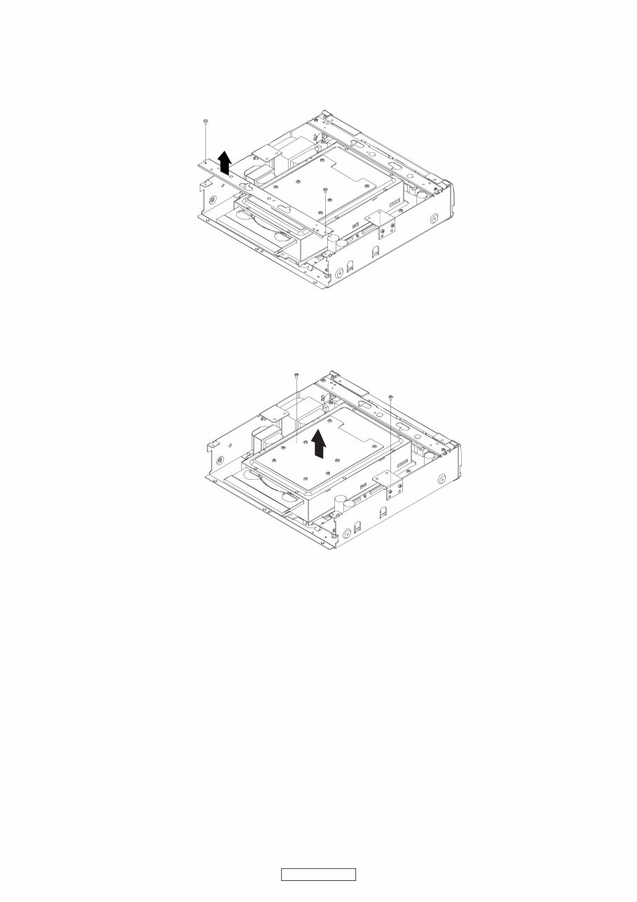
3. SACD メカのはずしかた
(1) フロントアングルを取り付けているネジ2本をはずし
ます。
(2) フロントアングルを矢印の方向にはずします。
(3) メカブラケットを取り付けているネジ 2 本をはずしま
す。
(4) SACD メカを矢印の方向にはずします。
※ SACD メカを廃棄する場合は、メカ分解図のように分解
してください。
3. SACD Mechanism
(1) Remove 2 screws, then detach Front Angle.
(2) Remove 2 Mecha Bracket screws, then detach SACD
Mechanism.
※ If SACD Mechanism is abandoned, disassembles
according to Mechanism exploded view.

7
DCD-CX3
組み立てかた
※ セットを組み立てるときは、トレイを閉めた状態にして
ください。
1. フロントパネルの取り付け
(1) シャーシに SACD メカをのせます。
※ この時点では、メカのネジ止めをおこないません。
(2) フロントアングルを取り付け、ネジ 2 本を締めます。
(3) フロントパネルを取り付け、ネジ 6 本を締めます。
※ ローダーパネルにキズを付けないよう、注意してく
ださい。
ASSEMBLY
※ When assembling set, close the tray.
1. Front Panel
(1) Put the SACD Mechanism on the chassis.
※ At this time, the screw of the mechanism is not tight-
ened
(2) 2 screws of Front Angle are tightened.
(3) 6 screws of Front Panel are tightened.
※ Loader Panel is the parts to which a scratch tends to
be attached. Be fully careful in the case of work.

8
DCD-CX3
2. SACD メカの取り付け
(1) SACD メカを矢印①の方向に押し付けながら左右 ( 矢
印② ) に動かし、フロントパネルとトレイの左右の隙
間が均一になる位置で、後方のネジ 2 本を締めます。
(2) 電源を ON 状態にして、トレイを開け、再び電源 OFF
状態にしてください。
(3) フロントパネル上部の切り欠き部(2ヶ所)からネジ
取り付け部が見える位置まで、トレイを押し込みま
す。
(fig. A 参照)
(4) ネジ2本を締めます。(fig.B 参照)
2. SACD Mechanism
(1) While forcing the SACD mechanism to the direction of
the arrow ① , adjust the left and right (the arrow ② ). 2
screws of the rear are tightened at the position where
the open part of front panel and the space of the both
ends of the tray become equal.
(2) Turn the power "ON", open the tray and turn the power
"OFF".
(3) Press the tray in to the position at which position in
which a screw is tightened can be seen through the 2
cuts in the top of the Front Panel. (Refer to Fig. A)
(4) 2 screws are tightened. (Refer to Fig. B)
①
②
Front Panel
Tray
fig. A
fig. B
MECHA HOLDER
MECHA BRACKET
9
DCD-CX3
3. サイドパネルの取り付け
(1) サイドパネルを矢印の方向に押しながら、ネジ 4 本を
締めます。
4. トップパネルの取り付け
(1) サイドパネルとトップパネルを矢印の方向に同時に
押しながら、トップパネルのネジ 8 本を締めます。
3. Side Panel
(1) 4 screws are tightened forcing Side Panel in the direc-
tion of an arrow.
4. Top Panel
(1) 8 screws of Top Panel are tightened, forcing Side Pan-
el and Top Panel simultaneously to the direction of the
arrow.
10
DCD-CX3
DIAGNOSTICS OF OPTICAL PICKUP
AND REPLACING TRAVERSE UNIT
Make failure diagnostics of the Optical Pickup as follows.
If the laser drive current (Iop) becomes more than 1.5 times
of the initial value, the Optical Pickup should be replaced.
The laser drive current initial value is checked by "Iop
checked Method" of next page.
In case of replacing the Pickup, change the whole part of the
Traverse Unit.
No mechanical adjustment is necessary after the replace-
ment.
光ピックアップの故障診断とトラバー
スユニットの交換
次の順序で故障診断をおこなってください。
レーザー駆動電流 Iop 値が初期値の 1.5 倍以上になってい
る場合は光ピックアップ交換の目安となります。
レーザー駆動電流初期値は、次ページ "Iop 値の確認方法 "
で確認できます。
ピックアップ交換の場合は、トラバースユニット単位での
交換となります。メカの調整は不要です。
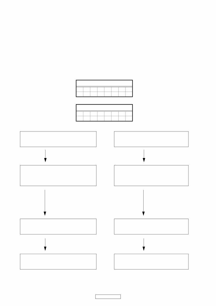
レーザー駆動電流初期値 :
Laser drive current initial value:
FL Display (The display part of 8 digits)
1 2 3 4 5 6 7 8
T 2 3 ― m m m m
FL Display (The display part of 8 digits)
1 2 3 4 5 6 7 8
T 2 1 ― m m m m
Disc no read, unsteady playback, etc.
Laser drive current (Iop) check
HF wave form check
(Refer to WAVE FORMS)
Traverse Unit replacing
Laser current (Iop) memorizing after replacement
Present value exceeds the ini-
tial value by 1.5 times
ディスクを読み込まない
スムーズに再生しない、等
レーザー駆動電流 Iop 値の確認
HF 波形の確認
(WAVE FORMS 参照)
トラバースユニット交換
交換後にレーザー電流値の記憶
現在値が初期値の
1.5 倍になっている
CD:
DVD:
You're Reading a Preview
What's Included?
Fast Download Speeds
Online & Offline Access
Access PDF Contents & Bookmarks
Full Search Facility
Print one or all pages of your manual
$31.99
Viewed 14 Times Today


Secure transaction
What's Included?
Fast Download Speeds
Online & Offline Access
Access PDF Contents & Bookmarks
Full Search Facility
Print one or all pages of your manual
$31.99
This Denon DCD CX3 CD Stereo System service and repair manual is an essential resource for both professional mechanics and DIY enthusiasts. It contains comprehensive technical information required to effectively service and repair your stereo system.
- Specifications
- Adjustments
- Service Modes
- Disassembly & Assembly Instructions
- Troubleshooting
- Wave Forms
- Semiconductors
- Block Diagrams
- Printed Wiring Boards
- Schematic Diagrams
- Exploded Views
- Parts List Catalog
This official advanced service manual in high resolution format provides detailed insights into the inner workings of the stereo system, enabling efficient repairs and maintenance.
Specifications:
- Language: English
- Format: PDF
- Pages: 81


