

D&M Holdings Inc.
SERVICE MANUAL
e
e
Copyright 2012 D&M Holdings Inc. All rights reserved.
WARNING: Violators will be prosecuted to the maximum extent possible.
MODEL JP E3 E2 E1 E1C EA E2R EUT
DCD-720AE P P
DCD-520AE P P
CD PLAYER
Ver. 1
S0444-1V01DM/DG1205
• Some illustrations using in this service manual are slightly different from the actual set.
• Please use this service manual with referring to the operating instructions without fail.
• For purposes of improvement, specifications and design are subject to change without notice.

2
CONTENTS
ABOUT THIS MANUAL .............................................................3
What you can do with this manual ............................................3
Using Adobe Reader (Windows version) ..................................4
SAFETY PRECAUTIONS ..........................................................6
NOTE FOR SCHEMATIC DIAGRAM.........................................7
NOTE FOR PARTS LIST ...........................................................7
TECHNICAL SPECIFICATIONS ..............................................10
DIMENSION .............................................................................10
CAUTION IN SERVICING........................................................ 11
Initializing CD Player ............................................................... 11
Service Jig .............................................................................. 11
Note Handling and Replacement of the Laser pick-up .......12
1. Protection of the LD.............................................................12
2. Precautions when handling the laser CD mechanism .........12
3. Cautions on assembling and adjustment ............................12
4. Determining whether the laser pick-up is defective .............12
DISASSEMBLY ........................................................................13
1. MAIN ASSY .........................................................................15
2. FRONT PANEL ASSY .........................................................16
3. CD MECHANISM ASSY......................................................17
4. AUDIO/POWER ASSY ........................................................18
SPECIAL MODE ......................................................................19
Special mode setting button ....................................................19
1. Version display mode ..........................................................20
2. VFD check mode .................................................................20
3. Cold start mode ...................................................................20
4. CD test mode ......................................................................21
5. CD heart run mode ..............................................................24
6. Laser on time.......................................................................26
7. Main μ-com version up mode ..............................................26
8. Timer check mode ...............................................................26
WHEN THE MICROPROCESSOR IS REPLACED
WITH A NEW ONE...................................................................27
PROCEDURE FOR UPGRADING THE VERSION
OF THE FIRMWARE................................................................27
1. Update for IC11(TMPM330FWFG) ......................................28
2. Update for IC41(TMP92FD28AFG):USB μcom...................32
TROUBLE SHOOTING ............................................................40
FLOW CHART NO.1 ...........................................................40
FLOW CHART NO.2 ...........................................................40
FLOW CHART NO.3 ...........................................................41
FLOW CHART NO.4 ...........................................................41
FLOW CHART NO.5 ...........................................................41
FLOW CHART NO.6 ...........................................................42
FLOW CHART NO.7 ...........................................................42
FLOW CHART NO.8 ...........................................................42
FLOW CHART NO.9 ...........................................................43
MEASURING METHOD AND WAVEFORMS .........................44
WAVEFORMS .........................................................................46
BLOCK DIAGRAM...................................................................49
WIRING DIAGRAM ..................................................................50
LEVEL DIAGRAM....................................................................51
PRINTED WIRING BOARDS...................................................52
SCHEMATIC DIAGRAMS .......................................................57
POWER AUDIO ......................................................................57
FRONT USB............................................................................58
CD MCU ..................................................................................59
EXPLODED VIEW DCD720AE................................................60
EXPLODED VIEW DCD520AE................................................61
EXPLODED VIEW OF CD MECHANISM UNIT.......................62
PARTS LIST OF EXPLODED VIEW DCD720AE ....................63
PARTS LIST OF EXPLODED VIEW DCD520AE ....................65
PARTS LIST OF CD MECHANISM UNIT
DCD720AE&DCD520AE .........................................................67
PACKING VIEW .......................................................................68
PARTS LIST OF PACKING & ACCESSORIES DCD720AE ...68
PARTS LIST OF PACKING & ACCESSORIES DCD520AE ...69
SEMICONDUCTORS ...............................................................70
1. IC's ......................................................................................70
2. FL DISPLAY.........................................................................88
PARTS LIST OF PCB UNIT DCD720AE .................................89
AUDIO_POWER ASS'Y ..........................................................89
CD PCB ASS'Y DCD720AE ....................................................94
PARTS LIST OF PCB UNIT DCD520AE .................................98
AUDIO_POWER ASS'Y ..........................................................98
CD PCB ASS'Y DCD520AE ..................................................102
3
ABOUT THIS MANUAL
Read the following information before using the service manual.
What you can do with this manual
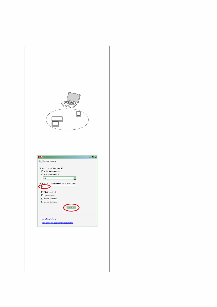
Search for a Ref. No. (phrase)
(Ctrl+Shift+F)
You can use the search function in Acrobat Reader to
search for a Ref. No. in schematic diagrams, printed
wiring board diagrams, block diagrams, and parts lists.
1.Press Ctrl+Shift+F on the keyboard.
• The Search window appears.
Ctrl
Shift
F
2.Enter the Ref. No. you want to search for in the
Search window, and then click the Search button.
• A list of search results appears.
3.Click an item on the list.
• The screen jumps to the page for that item, and
the search phrase is displayed.
4
Using Adobe Reader (Windows version)
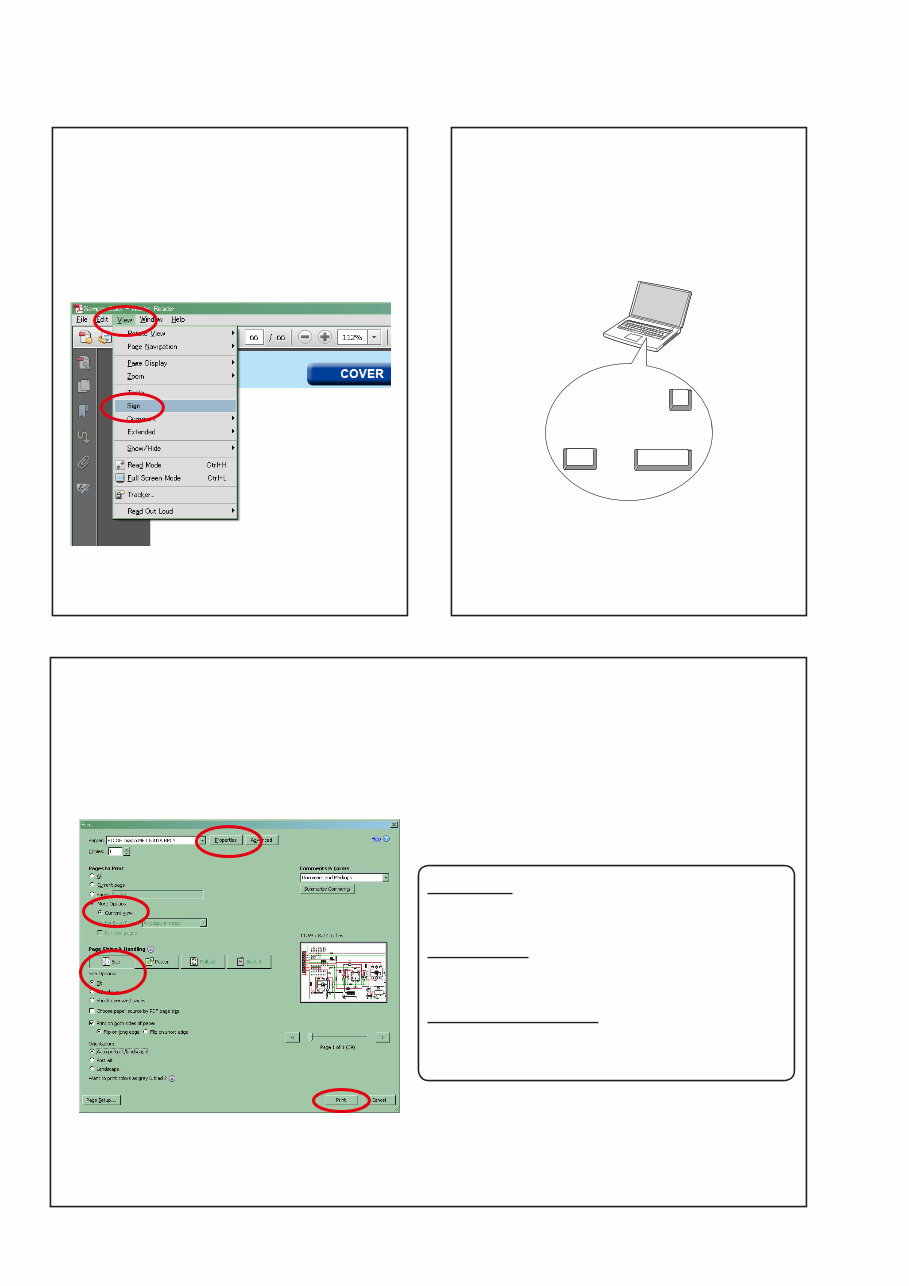
• Properties
Click this button and check that the printer is set to a
suitable paper size.
• Page to print
Select the following checkbox.
"More Options" : "Current View"
• Page Sizing & Handling
Select the following checkbox.
"Size" / "Size Options" : "Fit"
Add notes to this data (Sign)
The Sign function lets you add notes to the data in this
manual.
Save the file once you have finished adding notes.
[Example using Adobe Reader X]
On the "View" menu, click "Sign".
• The Sign pane appears.
[Example using Adobe Reader 9]
On the "Document" menu, click "Sign".
Magnify schematic / printed wiring board
diagrams - 1
(Ctrl+Space, mouse operation)
Press Ctrl +Space on the keyboard and drag the
mouse to select the area you want to view.
• The selected area is magnified.
Ctrl Space
0
• When you want to move the area shown, hold down
Space and drag the mouse.
• When you want to show a full page view, press
Ctrl+0 on the keyboard.
Print a magnified part of the manual
The Properties dialog box and functions will vary depending on your printer.
1. Drag the mouse to magnify the part you want to print.
2. On the "File" menu, click "Print".
3. Configure the following settings in the Print dialog box.
4. Click the Print button to start printing.
5
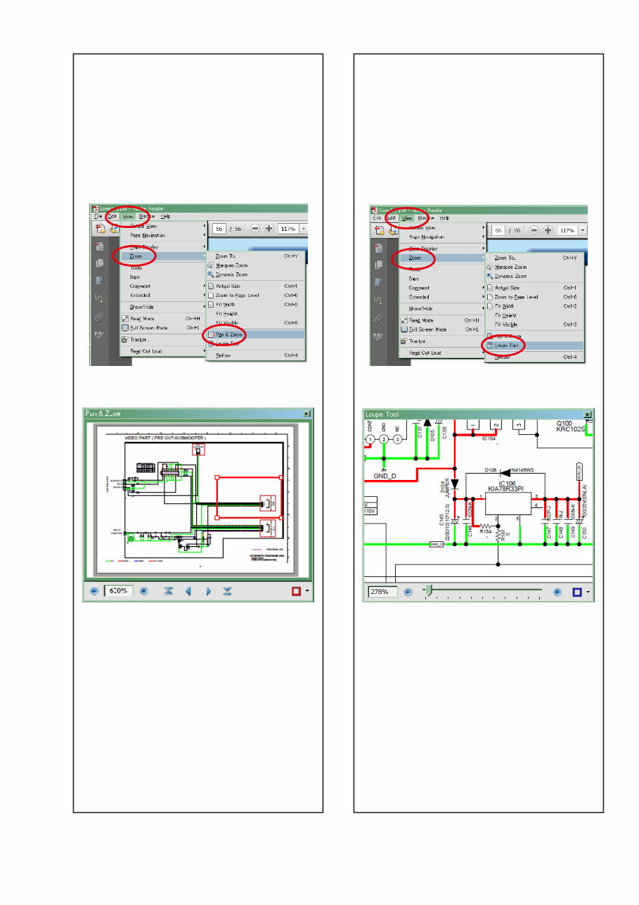
Magnify schematic / printed wiring board
diagrams - 2
(Pan & Zoom function)
The Pan & Zoom function lets you see which part of a
magnified diagram is being shown in a separate window.
[Example using Adobe Reader X]
On the "View" menu, point to "Zoom", and then click
"Pan & Zoom".
• The Pan & Zoom window appears on the screen.
[Example using Adobe Reader 9]
On the "Tools" menu, point to "Select & Zoom", and
then click "Pan & Zoom Window".
Magnify schematic / printed wiring board
diagrams - 3
(Loupe Tool function)
The Loupe Tool function lets you magnify a specific
part of a diagram in a separate window.
[Example using Adobe Reader X]
On the "View" menu, point to "Zoom", and then click
"Loupe Tool".
• The Loupe Tool window appears on the screen.
[Example using Adobe Reader 9]
On the "Tools" menu, point to "Select & Zoom", and
then click "Loupe Tool Window".

6
SAFETY PRECAUTIONS
The following items should be checked for continued protection of the customer and the service technician.
LEAKAGE CURRENT CHECK
Before returning the set to the customer, be sure to carry out either (1) a leakage current check or (2) a line to chassis
resistance check. If the leakage current exceeds 0.5 milliamps, or if the resistance from chassis to either side of the
power cord is less than 460 kohms, the set is defective.
Be sure to test for leakage current with the AC plug in both polarities, in addition, when the set's power is in each state (on,
off and standby mode), if applicable.
CAUTION Please heed the following cautions and instructions during servicing and
inspection.
◎ Heed the cautions!
Cautions which are delicate in particular for servicing
are labeled on the cabinets, the parts and the chassis,
etc. Be sure to heed these cautions and the cautions
described in the handling instructions.
◎ Cautions concerning electric shock!
(1) An AC voltage is impressed on this set, so if
you touch internal metal parts when the set is
energized, you may get an electric shock. Avoid
getting an electric shock, by using an isolating
transformer and wearing gloves when servicing
while the set is energized, or by unplugging the
power cord when replacing parts, for example.
(2) There are high voltage parts inside. Handle with
extra care when the set is energized.
◎ Caution concerning disassembly and
assembly!
Through great care is taken when parts were
manufactured from sheet metal, there may be burrs
on the edges of parts. The burrs could cause injury if
fingers are moved across them in some rare cases.
Wear gloves to protect your hands.
◎ Use only designated parts!
The set's parts have specific safety properties (fire
resistance, voltage resistance, etc.). Be sure to use
parts which have the same properties for replacement.
The burrs have the same properties. In particular, for
the important safety parts that are indicated by the z
mark on schematic diagrams and parts lists, be sure to
use the designated parts.
◎ Be sure to mount parts and arrange the wires
as they were originally placed!
For safety seasons, some parts use tapes, tubes or
other insulating materials, and some parts are mounted
away from the surface of printed circuit boards.
Care is also taken with the positions of the wires by
arranging them and using clamps to keep them away
from heating and high voltage parts, so be sure to set
everything back as it was originally placed.
◎ Make a safety check after servicing!
Check that all screws, parts and wires removed or
disconnected when servicing have been put back in
their original positions, check that no serviced parts
have deteriorate the area around. Then make an
insulation check on the external metal connectors and
between the blades of the power plug, and otherwise
check that safety is ensured.
(Insulation check procedure)
Unplug the power cord from the power outlet,
disconnect the antenna, plugs, etc., and on the power.
Using a 500V insulation resistance tester, check that
the insulation resistance value between the inplug and
the externally exposed metal parts (antenna terminal,
headphones terminal, input terminal, etc.) is 1MΩ or
greater. If it is less, the set must be inspected and
repaired.
Many of the electric and the structural parts used in
the set have special safety properties. In most cases
these properties are difficult to distinguish by sight, and
the use of replacement parts with higher ratings (rated
power and withstand voltage) does not necessarily
guarantee that safety performance will be preserved.
Parts with safety properties are indicated as shown
below on the wiring diagrams and the parts list in this
service manual. Be sure to replace them with the parts
which have the designated part number.
(1) Schematic diagrams.......Indicated by the z mark.
(2) Parts lists.......Indicated by the z mark.
The use of parts other than the
designated parts could cause electric
shocks, fires or other dangerous
situations.
CAUTION Concerning important safety
parts

7
NOTE FOR SCHEMATIC DIAGRAM
WARNING:
Parts indicated by the z mark have critical characteristics. Use ONLY replacement parts recommended by the manufacturer.
CAUTION:
Before returning the set to the customer, be sure to carry out either (1) a leakage current check or (2) a line to chassis resistance check. If
the leakage current exceeds 0.5 milliamps, or if the resistance from chassis to either side of the power cord is less than 460 kohms, the set
is defective.
WARNING:
DO NOT return the set to the customer unless the problem is identified and remedied.
NOTICE:
ALL RESISTANCE VALUES IN OHM. k=1,000 OHM / M=1,000,000 OHM
ALL CAPACITANCE VALUES ARE EXPRESSED IN MICRO FARAD, UNLESS OTHERWISE INDICATED. P INDICATES MICRO-MICRO
FARAD. EACH VOLTAGE AND CURRENT ARE MEASURED AT NO SIGNAL INPUT CONDITION. CIRCUIT AND PARTS ARE SUBJECT
TO CHANGE WITHOUT PRIOR NOTICE.
Parts indicated by "nsp" on this table cannot be supplied.
When ordering a part, make a clear distinction between "1" and "I" (i) to avoid mis-supplying.
A part ordered without specifying its part number can not be supplied.
General-purpose Carbon Chip Resistors are not included are not included in the P.W.Board parts list.
(Refer to the Schematic Diagram for those parts.)
Parts indicated by the z mark have critical characteristics. Use ONLY replacement parts recommended by the manufacturer.
General-purpose Carbon Film Resistor in the P.W.Board parts list. (Refer to the Schematic Diagram for those parts.)
Part indicated by "★" mark is not illustrated in the exploded view.
WARNING:
1.
2.
3.
4.
5.
6.
NOTE FOR PARTS LIST
8
WARNING AND LASER SAFETY INSTRUCTIONS
F ATTENTION D WARNUNG
WAARSCHUWING
AVVERTIMENTO
WARNING
Safety regulations require that the set be restored to its original condition
and that parts which are identical with those specified be used.
Veiligheidsbepalingen vereisen, dat het apparaat in zijn oorspronkelijke
toestand wordt terug gebracht en dat onderdelen, identiek aan de
gespecifieerde worden toegepast.
Bei jeder Reparatur sind die geltenden Sicherheitsvorschriften zu beachten.
Der Originalzustand des Gerats darf nicht verandert werden.
Fur Reparaturen sind Original-Ersatzteile zu verwenden.
Le norme di sicurezza esigono che l’apparecchio venga rimesso nelle
condizioni originali e che siano utilizzati pezzi di ricambiago idetici a quelli
specificati.
Les normes de sécurité exigent que l’appareil soit remis a l’état d’origine et
que soient utilisées les pièces de rechange identiques à celles spécifiées.
“Pour votre sécurité, ces documents
doivent être utilisés par des
spécialistes agrées, seuls habilités à
réparer votre appareil en panne.”
GB NL
I
D
I
F
GB
NL
All ICs and many other semi-conductors are
susceptible to electrostatic discharges (ESD).
Careless handling during repair can reduce life
drastically.
When repairing, make sure that you are connected
with the same potential as the mass of the set via a
wrist wrap with resistance.
Keep components and tools also at this potential.
Tous les IC et beaucoup d’autres semiconducteurs
sont sensibles aux décharges statiques (ESD).
Leur longévité pourrait être considérablement
écourtée par le fait qu’aucune précaution n’est prise
a leur manipulation.
Lors de réparations, s’assurer de bien être relié au
même potentiel que la masse de l’appareil et enfiler
le bracelet serti d’une résistance de sécurité.
Veiller a ce que les composants ainsi que les outils
que l’on utilise soient également a ce potentiel.
Alle IC und viele andere Halbleiter sind
empfindlich gegen elektrostatische
Entladungen (ESD).
Unsorgfältige Behandlung bei der Reparatur
kann die Lebensdauer drastisch vermindern.
Sorgen sie dafür, das Sie im Reparaturfall
dem Massepotential des Gerätes verbunden
sind.
Halten Sie Bauteile und Hilfsmittel ebenfalls
über ein Pulsarmband mit Widerstand mit auf
diesem Potential.
Alle IC’s en vele andere halfgeleiders zijn gevoelig
voor elektrostatische ontladingen (ESD).
Onzorgvuldig behandelen tijdens reparatie kan de
levensduur drastisch doen verminderen.
Zorg ervoor dat u tijdens reparatie via een polsband
met weerstand verbonden bent met apparaat.
Houd componenten en hulpmiddelen ook op
ditzelfde potentiaal.
Tutti IC e parecchi semi-conduttori sono sensibili
alle scariche statiche (ESD).
La loro longevita potrebbe essere fortemente ridatta
in caso di non osservazione della piu grande
cauzione alla loro manipolazione.
Durante le riparazioni occorre quindi essere
collegato allo stesso potenziale che quello della
massa dell’apparecchio tramite un braccialetto a
resistenza.
Assicurarsi che i componenti e anche gli utensili
con quali si lavora siano anche a questo potenziale.
LASER SAFETY
CAUTION VISIBLE AND INVISIBLE LASER RADIATION WHEN OPEN AVOID EXPOSURE TO BEAM
ADVARSEL SYNLIG OG USYNLIG LASERSTRÅLING VED ÅBNING UNDGÅ UDSÆTTELSE FOR STRÅLING
ADVARSEL SYNLIG OG USYNLIG LASERSTRÅLING NÅR DEKSEL Å PNES UNNGÅ EKSPONERING FOR STRÅLEN
VARNING SYNLIG OCH OSYNLIG LASERSTRÅLNING NÄR DENNA DEL ÄR ÖPPNAD BETRAKTA EJ STRÅLEN
VARO! AVATT AESSA OLET ALTTIINA NÄKYVÄLLE JA NÄKYMÄTTÖMÄLLE LASER SÄTEILYLLE. ÄLÄ KATSO SÄTEESEEN
VORSICHT SICHTBARE UND UNSICHTBARE LASERSTRAHLUNG WENN ABDECKUNG GEÖFFNET NICHT DEM STRAHL AUSSETSEN
DANGER VISIBLE AND INVISIBLE LASER RADIATION WHEN OPEN AVOID DIRECT EXPOSURE TO BEAM
ATTENTION RAYONNEMENT LASER VISIBLE ET INVISIBLE EN CAS D'OUVERTURE EXPOSITION DANGEREUSE AU FAISCEAU
USE OF CONTROLS OR ADJUSTMENTS OR PERFORMANCE
OF PROCEDURE OTHER THAN THOSE SPECIFIED HEREIN
MAY RESULT IN HAZARDOUS RADIATION EXPOSURE.
AVOID DIRECT EXPOSURE TO BEAM
WARNING
The use of optical instruments with this product will
increase eye hazard.
Repair handling should take place as much as possible with
a disc loaded inside the player
WARNING LOCATION: INSIDE ON LASER COVERSHIELD
This unit employs a laser. Only a qualified service person should
remove the cover or attempt to service this device, due to
possible eye injury.
100301DM
9
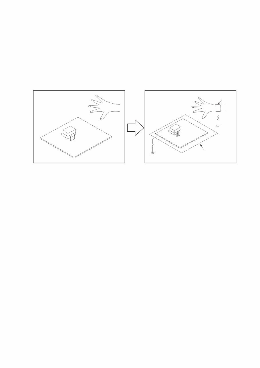
INSTRUCTIONS FOR HANDLING SEMI-CONDUCTORS AND OPTICAL UNIT
Electrostatic breakdown of the semi-conductors or optical pickup may occur due to a potential difference caused by
electrostatic charge during unpacking or repair work.
1. Ground for Human Body
Be sure to wear a grounding band (1 MΩ) that is properly grounded to remove any static electricity that may be
charged on the body.
2. Ground for Workbench
Be sure to place a conductive sheet or copper plate with proper grounding (1 MΩ) on the workbench or other surface,
where the semi-conductors are to be placed. Because the static electricity charge on clothing will not escape through
the body grounding band, be careful to avoid contacting semi-conductors with your clothing
<Incorrect>
CBA
Grounding Band
Conductive Sheet or
Copper Plate
1MΩ
1MΩ
<Correct>
CBA
10
TECHNICAL SPECIFICATIONS
[DCD-720AE] [DCD-520AE]
n Audio performance
• Analog output
Channels: 2 channels 2 channels
Playable frequency range: 2 Hz – 20 kHz 2 Hz – 20 kHz
Playable frequency response: 2 Hz – 20 kHz 2 Hz – 20 kHz
S/N: 112 dB 110 dB
Dynamic range: 100 dB 100 dB
Harmonic distortion: 0.0025 % (1 kHz) 0.003 % (1 kHz)
Wow & flutter: Below measurable limits Below measurable limits
Output level: 2.0 V (10 kΩ) 2.0 V (10 kΩ)
Signal type: 16-bit linear PCM 16-bit linear PCM
Sampling frequency: 44.1 kHz 44.1 kHz
Usable discs: Compact Disc Compact Disc
• Digital output
Optical: –15 – –21 dBm –15 – –21 dBm
Emission wavelength: 660 nm 660 nm
n General
Power supply: AC 230 V, 50/60 Hz AC 230 V, 50/60 Hz
Power consumption: 22 W 13 W
Power consumption in standby mode: 0.3 W 0.3 W
Weight : 4.1kg (DCD-720AE)
4.0kg (DCD-520AE)
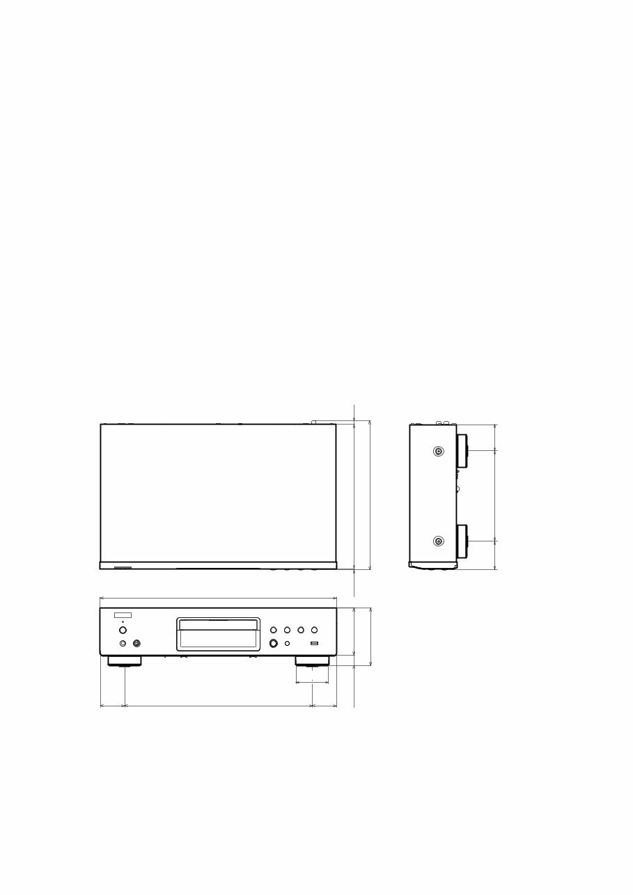
DIMENSION
265.0
273.0
166.0 50.0 49.0
19.0 88.0
107.0
434.0
344.0
60.0
45.0 45.0
2.0 6.0
You're Reading a Preview
What's Included?
 Lifetime Access
Fast Download Speeds
Online & Offline Access
Access PDF Contents & Bookmarks
Full Search Facility
Print one or all pages of your manual
$31.99
Denon DCD-720AE DCD-520AE CD PLAYER Service Manual
Viewed 28 Times Today

What's Included?
Lifetime Access
Fast Download Speeds
Online & Offline Access
Access PDF Contents & Bookmarks
Full Search Facility
Print one or all pages of your manual
$31.99

Secure transaction
What's Included?
Lifetime Access
Fast Download Speeds
Online & Offline Access
Access PDF Contents & Bookmarks
Full Search Facility
Print one or all pages of your manual
Description
The Denon DCD-720AE DCD-520AE CD PLAYER Service Manual is a comprehensive guide for repairing and maintaining the Denon DCD-720AE and DCD-520AE CD players. It is available in English and comes in a digital format compatible with both Windows and Mac platforms.


