

Bang & Olufsen Beosound 9000 mk3 Service Manual
What's Included?
Fast Download Speeds
Online & Offline Access
Access PDF Contents & Bookmarks
Full Search Facility
Print one or all pages of your manual
BeoSound 9000 MKIII
Type 2571, 2572, 2573, 2574, 2575, 2576, 2577, 2580
Service Manual
English, German, French
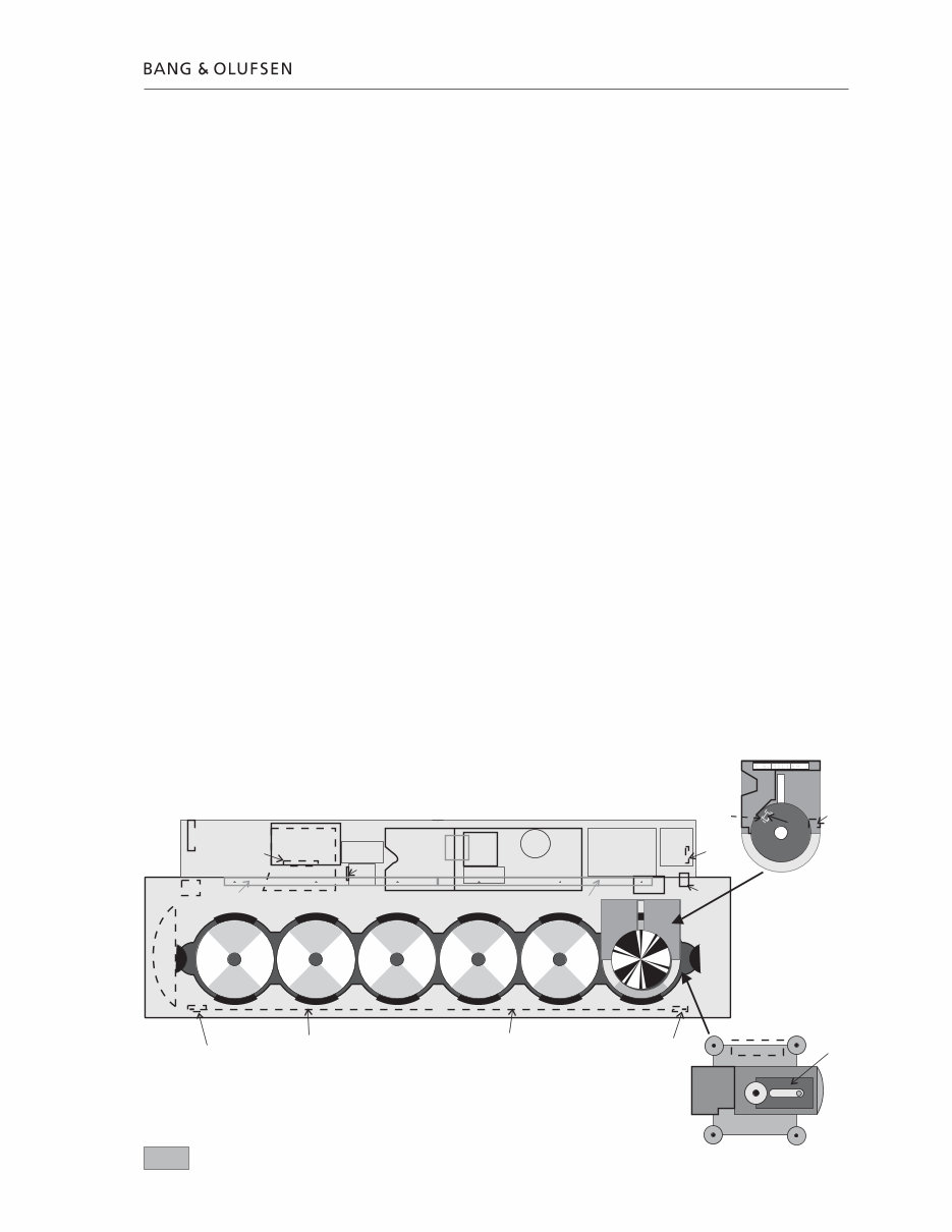
Survey of modules 1.1
1 FM/AM - RDS ....................................... diagram A, AA, B, BB
page 2.11, 12, 13, 14
3 Main Microcomputer ...........................................diagram J
page 2.24
4 Mains Filter ......................................................... diagram N
page 2.29
5 Mains Relay .....................................................diagram N, O
page 2.29, 30
7 Display ................................................................... diagram I
page 2.23
9 Sledge Position ...................................................diagram M
page 2.28
11 Main Keyboard, right ......................................... diagram H
page 2.22
12 Main Keyboard, left ........................................... diagram H
page 2.22
13 Secondary Keyboard .......................................... diagram H
page 2.22
14 IR Receiver ........................................................... diagram H
page 2.22
20 ML Interface ......................................................... diagram E
page 2.18
21 Headphone ......................................................... diagram G
page 2.20,
22 Clamper Position .............................................. diagram I, L
page 2.23, 26
24 Light Indication, left .............................................diagram J
page 2.24
25 Light Indication, right ..........................................diagram J
page 2.24
26 End Stop Detector ..............................................diagram M
page 2.28
27 Safety TX .............................................................diagram M
page 2.28
28 Safety RX .............................................................diagram M
page 2.28
29 Lamp ...................................................................... diagram I
page 2.23
30 IR Transmitter, tacho clamper .............................. diagram I
page 2.23
31 IR Reciever, tacho clamper ................................... diagram I
page 2.23
32 Input/output Select, Sound Adj. ................ diagram E, F, G
page 2.18, 19, 20
34 Power Supply .......................... diagram C, D, G, H, I, J, L, N
page 2.16, 17, 20, 22, 23, 24, 26, 29
35 Motor Control ................................................. diagram L, M
page 2.26, 28
37 Lid Motor ............................................................diagram M
page 2.28
41 CD VAM 1250
CD ......................................................................... diagram C
page 2.16
Turn Table Motor Control .................................. diagram D
page 2.17
95 CD Mechanism, VAM 1250 ............................. diagram C, D
page 2.16, 17
35
3
34
1
20
21
14
27
28
26
5
37
4
9
7
30
31
29
25
24
12
11
13
41
22
95
32
= PCB13, PCB24 and PCB25 placed on the chassis topplate

SPECIFICATION GUIDELINES FOR SERVICE USE BeoSound 9000 MKIII
With FM and AM range and RDS Type 2571 (EU), 2572 (GB), 2573 (USA-CDN), 2574 (J), 2575 (AUS),
2576 (TWN), 2577 (KOR), 2580 (LAT)
Operation Direct keyboard
Beo4, BeoLink 1000
Mechanical functions
Change from playing CD1 to playing CD6
(Lid closed and known CD’s) < 6.5 sec., typical 4 sec.
Position of CD Typical ±1°
Tuner
Number of Programmes 60
Stereo / Mono selection Automatic / manual
Tuner, FM section
Range 87.5-108 MHz
76-90 MHz f. type 2564
Aerial impedance 75 ohm
Usable sensitivity mono (30 dB) Typical 11dBf - 1μV
50 dB quieting stereo ≤ 41dBf
Signal-to-noise at 65 dBf mono ≥ 69dB
Signal-to-noise at 65 dBf stereo ≥ 64dB
Frequency response 20-15000Hz
Distortion + noise mono ≤ 0.6%
Distortion + noise stereo ≤ 0.6%
Intermodulation stereo Typical 0.1%
Stereo channel separation Typical 30dB
Subcarrier product rejection ≥ 50dB
Tuner, AM section
Range LW 153-279 kHz f. type 2571, 2572, 2575, 2576, 2577
MW 522-1611 kHz f. type 2571, 2572, 2575, 2576, 2577
MW 530-1710 kHz f. type 2573, 2580
MW 522-1629 kHz f. type 2574
Antenna Loop 18.1μH (Special)
LW sensitivity 20 dB S/N ratio Typical 66dBμV/m ( 2mV/m )
MW sensitivity 20 dB S/N ratio Typical 60dBμV/m ( 1mV/m )
Harmonic distortion Typical 0.4 %
CD Player
Number of CD’s 6
Disc types 12 cm (5”), 8 cm (3”) with adaptor
Frequency range 20-20.000 Hz ±1dB
Signal-to-noise ratio A-weighted Typical 101dB
Dynamic range ≥ 98 dB
Harmonic distortion ≤ 0.1%
Channel separation ≥ 50 dB
Channel difference ≤ ±1dB
Converter system Bitstream
Preamplifier section
Harmonic distortion ≤ 0.1%
Frequency range ±1dB 10-20000Hz
Channel separation ≥ 50dB
Source separation ≥ 80dB
Signal-to-noise A-weight ≥ 90dB
Volume control ≥ 90dB
Bass control 7.0dB ±2dB at 100Hz
Treble control 7.0dB ±2dB at 10kHz
1.2 Specification guidelines for service use
Specification guidelines for service use 1.3
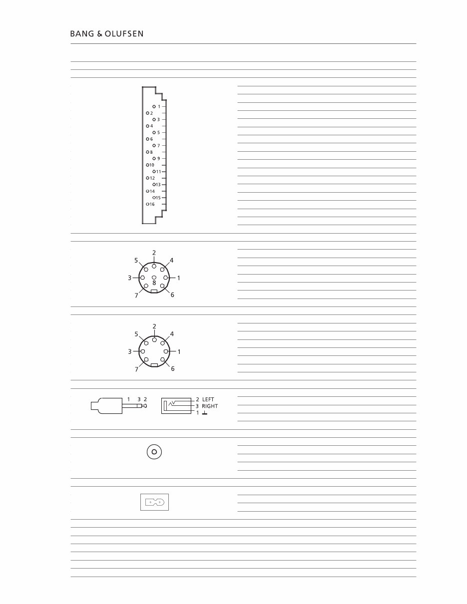
Connections
Master Link Pin 1 Data-, -0.5 V ±0.2 V in relation to Data+
Pin 2 Data+, +0.5 V ±0.2 V in relation to Data-
Pin 3 ML connect > 3 V
Pin 4-6 +supply voltage, +7 V to +15 V
(in stand-by +3 V to +15 V)
Pin 7-10 Not used
Pin 11 -supply voltage, -7 V to -15 V
(in stand-by -2 V to -15 V)
Pin 12 +supply voltage, +7 V to +15 V
(in stand-by +3 V to +15 V)
Pin 13 Audio L- in/out, 2 V Bal, in relation to Audio L+,
Rin 4.4 MW, Rout 150 Ω
Pin 14 Audio L+ in/out, 2 V Bal, in relation to Audio L-,
Rin 4.4 MW, Rout 150 Ω
Pin 15 Audio R- in/out, 2 V Bal, in relation to Audio R+,
Rin 4.4 MW, Rout 150 Ω
Pin 16 Audio R+ in/out, 2 V Bal, in relation to Audio R-,
Rin 4.4 MW, Rout 150 Ω
Shield GND Pin 1 Power up (ON = >2.7 V -1mA)
Pin 2 Signal GND
Pin 3 Audio L out 0 V to 2 V RMS
Pin 4 Speaker ON (ON = >2.7 V -1 mA)
Pin 5 Audio R out 0 V to 2 V RMS
Pin 6 Datalink out (High = >4 V, Low = <0.2 V)
Pin 7 Data GND
Pin 8 PL+ ON Pin 1 Audio L out 1 V RMS, Rout 1 kΩ
Pin 2 GND
Pin 3 Audio L in 0.25 V RMS to 2 V RMS, Rin 47 kΩ
Pin 4 Audio R out 1 V RMS, Rout 1 kΩ
Pin 5 Audio R in 0.25 V RMS to 2 V RMS, Rin 47 kΩ
Pin 6-7 Not used Ø 3.5 mm, 220 W
Digital output CD AES / EBU
IEC 958
0.5Vpp, 75W, 1%
Mains Cable included
Type 2571, 2572, 2577, 2580 – 230V AC
Type 2573, 2576 – 120V AC
Type 2574 – 100V AC
Type 2575 – 240V AC
Power frequency 50-60 Hz
Power consumption Stand.by Typical 1.0W
Power consumption Typical 15W

1.4 Specification guidelines for service use
Dimensions
W x H x D 86.9 x 7 x 30.1 cm
Weight 11.5kg
Finish Black, aluminium
Optional accessories
Beo4 Type 1624, 1625 (I)
Wall bracket horizontal Type 2054
Wall bracket vertical Type 2063
Bracket Type 2053
Stand, adjustable in two heights Type 2065
Cable cover Type 2062
AM loop antenna 8720047
FM antenna 8720048
Type Transformer PCB5 PCB34 PCB1 Mains cable
Mains Relay Power Supply FM/AM
2571 EU 8013551 EU-230V AC 8005661 EU 8000512 EU 8000462 EU 6100273
2572 GB 8013551 EU-230V AC 8005661 EU 8000512 EU 8000462 EU 6100329
2573 US 8013549 US-120V AC 8005664 US 8000536 US 8000462 EU 6100307
2574 JAP 8013548 JAP-100V AC 8005661 EU 8000512 EU 8000535 JAP 6100331
2575 AUS 8013550 AUS-240V AC 8005661 EU 8000512 EU 8000462 EU 6100332
2576 TWN 8013549 US-120V AC 8005664 US 8000536 US 8000462 EU 6100307
2577 KOR 8013551 EU-230V AC 8005661 EU 8000512 EU 8000462 EU 6100386
2580 LAT 8013551 EU-230V AC 8005661 EU 8000512 EU 8000462 EU 6100273
Subject to change without notice
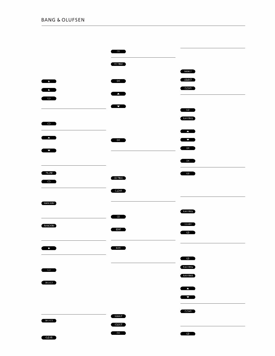
Brief operation guide 1.5
Repeat this procedure for all
the CDs you have loaded…
If you want to clear the posi-
tions for a CD, move the car-
riage to the CD in question…
Press to access the positioning
then function to clear the position
then
Press to clear the position
Naming CDs
Press to play CD
then
Press to access the naming
function
then
Press to reveal the characters
or or numbers one by one
then
Press to move to next
character position
then
Press to store the name
Press while you are naming
CDs or track series in order
to automatically store the
name and exit the naming
function
To clear a name, follow this procedure…
Press to access the naming
function
then
Press to clear the name
then
Press to return to normal
source operation
Listing CDs
Press to play CD
Press to access the naming list
then [CD LIST] appears briefly,
then the name of the current
CD appears
Press to list the names one
or by one and return to names
further up the list
Press to clear a name while
the appropriate name is
displayed
Press to return to normal
source operation
BRIEF OPERATION GUIDE
For more detailed operation see
User’s guide.
Programming a series of tracks
for one CD
Press to play CD
Press to scan the CD
[EDITING?] appears on the
display
then
Press to start scanning the
tracks
Press to include a track
number in the series
or
Press to exclude a track
number from the series
[EDITING OK] appears on the
display when you have
included or excluded the last
track…
then
Press to accept the track
series
To clear a track series…
Choose the CD whose track
series you want to clear
then
Press to access the program-
ming option
then
Press to clear the track series
altogether
Playing edited CDs
Press to start playback of a CD
then
Press to display [EDIT ON]
and start edited playback
Press twice to play a CD in
full and cancel EDIT – [EDIT
OFF] appears on the display
Positioning CDs
Load and adjust a CD manually…
Then press the direct CD
selection button next to this
CD to move the carriage to
the CD …
then
Press to access the
then positioning function for CDs
then
Press to store the position
for this CD
Closeup operation:
Loading CDs
Press to raise the glass door
Press to lower the glass door
or
Press to lower the door and
start playing
CD playback
Press to play a CD
Press to play the next track
on a CD
or
Press to play the same track
again or press twice to play
the previous track
Press to pause playback
Press to resume playing
Random
Press to display [RANDOM
ON] and cut in the random
play function
Press twice to display
[RANDOM OFF] and cancel
the random play function
Press to switch to stand-by
Choosing a sequence of discs
Press to start playback of a CD
Press SELECT and [SELECT
DISC] will appear on the
display
Press the direct CD selection
buttons next to the CDs you
want to include…
Press SELECT to start clearing
a sequence and play all six
CDs
then
Press to clear the sequence
1.6 Brief operation guide
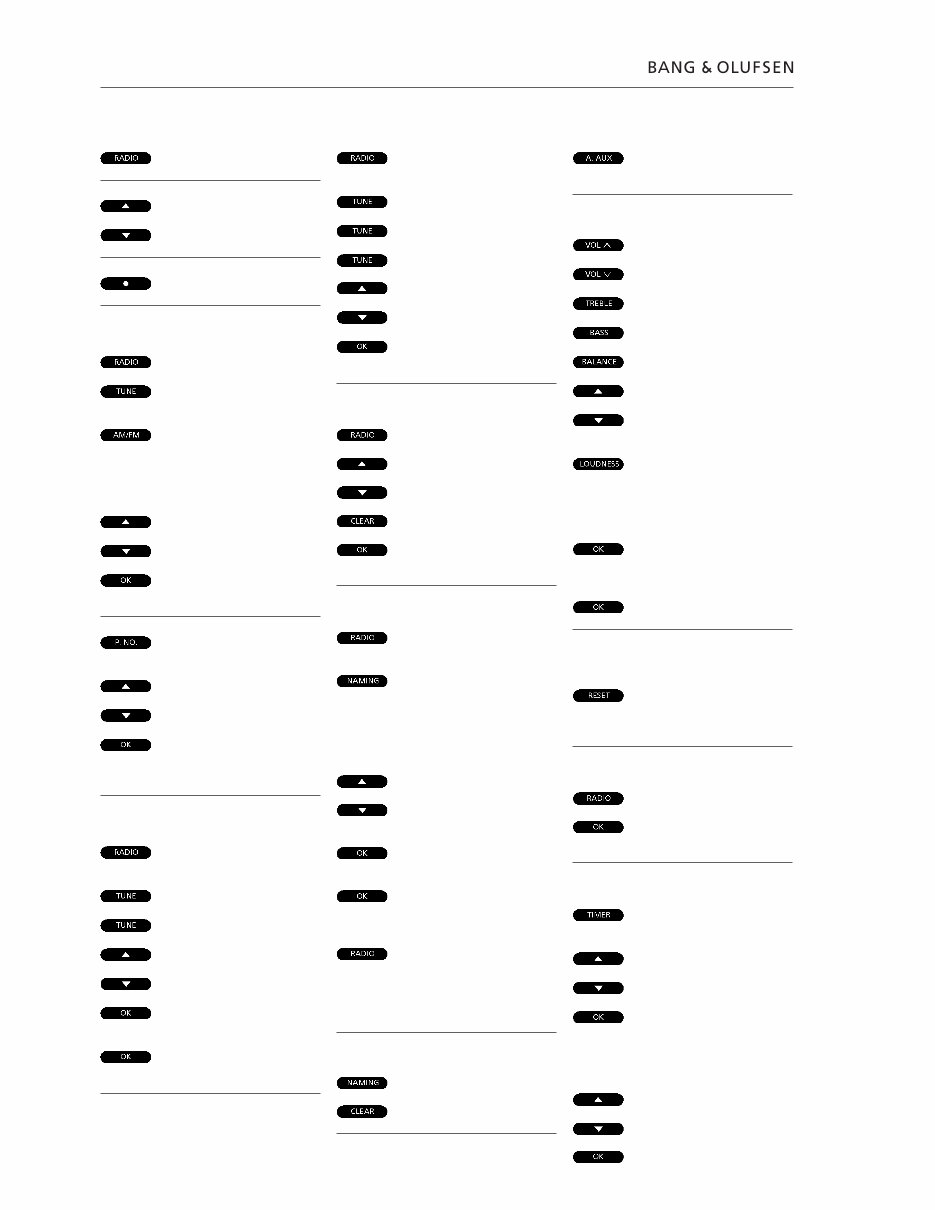
Playing your radio programs
Press to turn on the radio
Press to step through your
or radio programs
Press to switch to stand-by
Presetting radio stations
Press to turn on the radio
Press to start the tuning
function
Press to select [AM] or [FM],
switches from one to the
other, check display for an
indication of which one you
have chosen
then
Press to search for a radio
or station up or down the
frequency band
then
Press to accept the station
you have found
Press to change the displayed
program number
then
Press to select for a program
or number – up or down
then
Press to store your new radio
program – [STORED] appears
on the display
Fine tuning a radio station
Press to turn on the radio pro-
gram you want to fine tune
Press to start the fine tuning
then function
Press to fine tune your
or program towards a higher or
lower frequency
then
Press to accept your fine
tuned program
then
Press again to store program
and program number
Mono/stereo reception
Press to turn on the relevant
radio program
Press to choose [MONO] or
then [STEREO]
then
then
Press to switch from stereo
or to mono
Press to store your new tu-
ning on the program number
Clearing presets...
Press to turn on the radio
Press to search for program
or number
Press to clear the program
then
Press to confirm the clearing
of the radio program
Naming radio programs
Press to turn on the radio
program you want to name
Press to start the naming
function.
The first of the twelve cha-
racter positions blinks, indi-
cating that you can start
“writing” a name
Press to reveal the characters
or one by one
Press to reveal previously
shown characters
then
Press to move to the next
character position
then
Press to store the name of
the radio station [NAMING
OK] will appear on the display
or
Press to store the name and
exit the naming function
You can press RADIO at any
time to store and exit the
naming function
To clear a name…
Press to access the naming
then function
Press to clear the name
Playing auxiliary sources
Press to select extra
equipment
Adjusting sound
Press to raise the volume
Press to lower the volume
Press to access treble
Press to access bass
Press to access balance
Press to raise or lower the
or treble and bass levels; or
adjust the balance between
the left and the right speaker
Press to see the status of the
loudness adjustment function
– [LOUDNESS ON] or [LOUD-
NESS OFF]. Press LOUDNESS
again to change the setting
Press to accept all sound
levels - [SOUND OK?]
appears on the display
then
Press to store all sound levels
If you have not stored your
sound adjustments...
Press to reset the sound
levels to their previously
stored settings
Switching displays, example
Press to turn on the radio
Press repeatedly to change
the radio display indication
Programming Timers
Press to start programming
timers
then
Press to choose a source for
or your Timer or choose a Timer
stand-by
then
Press to accept the Timer
Then program when you
want the Timer to start and
stop…
Press repeatedly until you
or have found the exact time
for starting a Timer play
then
Press to accept start
Brief operation guide 1.7
Repeat the procedure with
the ▲ and ▼ buttons and OK
to program the exact timer
for stopping a Timer
To program a [SINGLE DATE]
Timer...
Press to display the date you
or want to program a Timer for
then
Press to accept the selection
then
Press to store your Timer
programming and return to
normal source operations
Checking or clearing Timers
Press to check your timers
then
Press to see timer program-
or ming number, source and
program number of
individual timer entries
Press repeatedly to display
the details of a particular
programming
When the display reads [OK ?]
then
Press to display [NEXT ?] to
or see your next timer program-
ming entry
then
Press to see your next entry –
If there are no more entries,
[NO MORE], will appear on
the display
Press clear while information
regarding a timer program-
ming is displayed on the
display – [CLEARED] will
appear on the display after
pressing CLEAR
Setting and using the built-in
clock
Press to show the clock
Press to see the date and
year
To display the clock
permanently…
Press when Date and Year is
displayed and change the
display to time and ON e.g.
[14:40 ON] – press again to
cancel the permanent
showing of the clock e.g.
[14:41 OFF].
Option programming Beo4
hold
while pressing
Until the Beo4 display reads
OPTIONS?
then
Until the display reads A:OPT
then
Disable the remote control
function
or
Enable the remote control
function
Option programming
BeoLink 1000
Disable the remote control
function
or
Enable the remote control
function
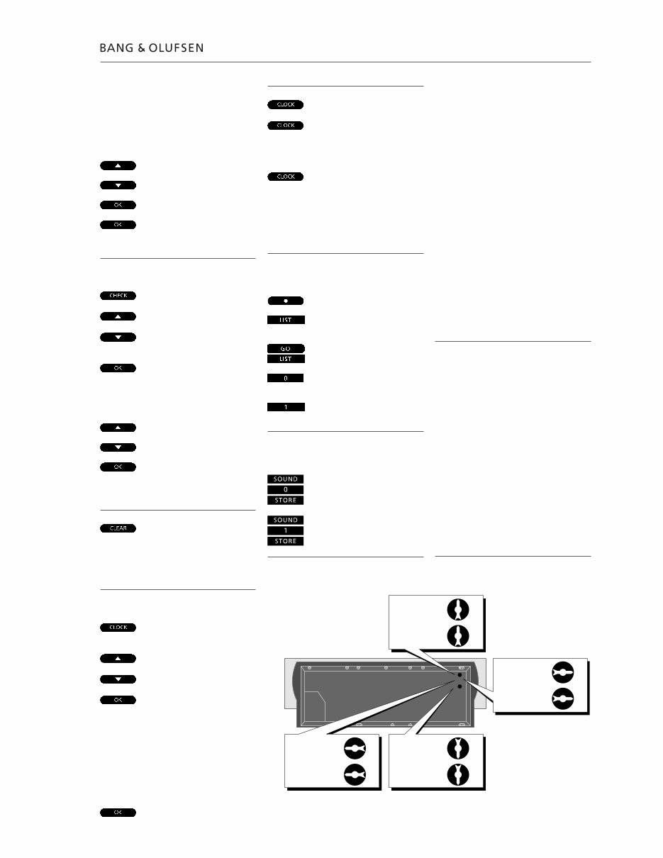
Centering the CD drive mechanism
Centered for a horizontal position.
Used for the bracket type 2054.
Centered for a vertical
position.
Centered for a
horizontal position.
Used for the bracket
type 2053.
Centered for a flat or near
flat position. This is the
factory setup.
Automatic demonstration
The product can be brought into
automatic demonstration mode in which
it plays back 90 randomly chosen tracks.
Each track is played back for 20 seconds.
Load six CD’s with at least ten tracks each.
Bring the product into stand-by.
Press: SHIFT 9 1 9 9 6.
The remote control terminal must be in
audio mode.
(SHIFT is found under LIST on Beo4)
The automatic demonstration can be
stopped by bringing BeoSound 9000 into
stand-by, which is done by actuating
stand-by on the product.
During the automatic demonstration the
sound will be muted. Demute the product
if you want sound.
Locking of glass lid
The glass lid can be locked so that it
cannot be operated on the product.
Press: SHIFT 9 0 3 6 9.
The remote control terminal must be in
audio mode.
The display reads: LOCK.
The function is stopped by pressing:
SHIFT 9 0 3 6 9.
The remote control terminal must be in
audio mode.
SHIFT is found under LIST on Beo4
The display reads: UNLOCK.
The sledge must be in
position 1.
Press to call up the built-in
clock
then
Press to set time, date/month
or or year…
then
Press to accept the changes
and reveal the next display -
Repeat this setting
procedure for date/month
and year…
When you have set or
changed the year, the
display now reads [CLOCK
OK?]
then
Press to store your new
setting of the clock

1.8 Brief operation guide
The PIN-code system
Activate the PIN-code system
While the BeoSound 9000 is in stand-by
mode you can set up the PIN-code.
Change or delete your PIN-code
While the PIN-code function is turned on you
can always make changes to the PIN-code.
Press p twice followed
by PAUSE to activate
the PIN-code function.
The display shows NEW
PIN for 1.5 sec.…
…then you can enter a
PIN-code
Press to select a digit*
Press to accept the digit
The digit is replaced by a
*
and the next under-
score blinks. Continue to enter the last three digits
in the same manner.
If you wish to change the entered digits…
Press to start entering
from the beginning
When the PIN-code has been entered…
Press to accept the PIN-
code. The display shows
CONFIRM for 1.5 sec.…
…then re-enter the PIN-
code
Press to confirm the PIN-
code
The display shows that
your setting is stored
If an incorrect code is entered the second time
you must set up the PIN-code from the beginning.
Press p twice followed
by PAUSE to activate
the PIN-code function
Enter the current PIN-
code. The display shows
NEW PIN?
Press to choose from
the two options NEW
PIN? or PIN OFF?
Select NEW PIN? to change your PIN-code
Enter the new PIN-code
Press to accept the new
PIN-code. The display
shows CONFIRM for 1.5
sec.…
…then re-enter the new
PIN-code
Press to confirm the
new PIN-code
The display shows that
your new PIN-code is
stored
Select PIN OFF? to delete your PIN-code
The PIN-code function is
disabled and the display
shows DELETED for 3 sec.
For security reasons it is only possible to change or
verify the PIN-code five times within a period of 3
hours. If an incorrect code is entered five times,
BeoSound 9000 is turned off, and must be left in
stand-by mode for 3 hours, before you may try
again.
p
p
PAUSE
NEW PIN
PIN ____
m
p
OK
RESET
OK
CONFIRM
PIN ____
OK
STORED
PIN ____
OK
CONFIRM
PIN ____
OK
STORED
DELETED
p
p
PAUSE
PIN ____
NEW PIN?
m
p
NEW PIN?
PIN OFF?
Using your PIN-code
When a PIN-code has been programmed, and
the BeoSound 9000 has been disconnected
from the mains for more than 30 minutes, you
must enter the PIN-code when the BeoSound
9000 is turned back on.
Enter the PIN-code
Press to select a digit
Press to accept the digit
When the PIN-code has
been entered the
display returns to the
relevant source display
e.g. RADIO 1
If an incorrect PIN-code is entered the display will
show ERROR and you may try again. After the
fifth try, the BeoSound 9000 is turned off, and
must be left in stand-by mode for 3 hours, before
you can try again.
PIN ____
m
p
OK
RADIO 1
Did you forget your PIN-code?
Should you forget your PIN-code you can
require a five-digit Master Code from your
Bang & Olufsen retailer.
When you have received a Master Code…
When the display is
open for PIN-code
input…
Press the p button for
more than 3 seconds to
change the display to fit
5 digits
Enter the Master Code
Press to select a digit
Press to accept the digit
The display shows that
the PIN-code lock is off
When the Master Code is entered, the BeoSound
9000 can be used without entering the code
again.
PIN ____
p
PIN _____
PIN _____
m
p
OK
DELETED
*NOTE!: It is also possible to enter the digits using
the number keys 0 – 9 on your Beo4 remote
control.
Explanation of diagram 2.1
Explanation of diagram
Type numbers of transistors and ICs are indicated on the diagrams. If the position
is followed by an asterisk the spare part number must always be used because the
component in question has been specially selected, e.g. IC4*.
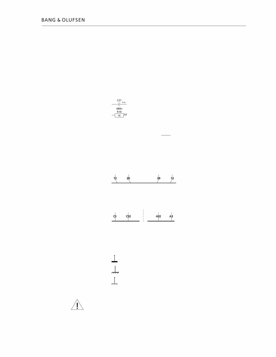
Component print and coordinate system
The largest PCBs have component prints and a coordinate system on both the
primary and the secondary side.
On the diagrams every component has a coordinate number.
This indicates in which coordinate on the PCB the component is situated. The
coordinate numbers are written in smaller print types than the position numbers.
= C27 is placed on the primary side in coordinate 1A.
= R10 is placed on the secondary side in coordinate 2B.
Control circuit
In certain control circuits the active mode is indicated by a function term or by an
abbreviation. This may be e.g. ST.BY. = low in the stand-by mode or ST.BY. = high
in the stand-by mode.
Wiring connections
The wiring connections on the diagrams are assembled in ‘bundles’.
The individual wires are provided with one of the following codes:
INTERNAL CONNECTION ON
ONE DIAGRAM PAGE
Internal connections on a diagram page are indicated by a number.
The bend of the wire indicates in which direction the other end of the wire is
found.
CONNECTION TO ANOTHER
DIAGRAM PAGE
A connection to another diagram page is indicated by a number as well as by a
letter of the diagram to which the connection leads.
Ground symbols
Three different ground symbols are used in the set.
= Ground
= Chassis
= Coarse ground
Symbol of safety components
When replacing components with this symbol, components with identical part
numbers must be used. The new component must be mounted in the same way
as the one replaced.
DIAGRAM A DIAGRAM C
You're Reading a Preview
What's Included?
Fast Download Speeds
Online & Offline Access
Access PDF Contents & Bookmarks
Full Search Facility
Print one or all pages of your manual
$33.99
Viewed 72 Times Today


Secure transaction
What's Included?
Fast Download Speeds
Online & Offline Access
Access PDF Contents & Bookmarks
Full Search Facility
Print one or all pages of your manual
$33.99
The Bang & Olufsen Beosound-9000 mk3 (type 2571, 2572, 2573, 2574, 2575, 2576, 2577, 2580) Service Manual is available in English, German, and French languages. It is 100% satisfaction guaranteed and virus-free. The format is suitable for Windows XP, Vista, 7, and Mac operating systems. The manual is fully bookmarked and includes chassis & electrical information, wiring diagrams, technical diagnostic procedures, disassembly & installation procedures, as well as numerous illustrations and schematic diagrams. This comprehensive manual is used by dealership technicians and is suitable for both professional mechanics and DIY enthusiasts. You have the flexibility to print specific pages or the entire manual to facilitate the required repairs.


