

SERVICE MANUAL
Sony Corporation
Published by Sony Techno Create Corporation
SPECIFICATIONS
9-893-631-01
2012L33-1
© 2012.12
US Model
Canadian Model
AEP Model
UK Model
E Model
WX-GT90BT
Russian Model
WX-GT90BTE
Indian Model
WX-GT99BT
Ver. 1.0 2012.12
Model Name Using Similar Mechanism
MEX-BT4100U/
WX-GT80UE/GT80UI/GT88UI
Mechanism Type MG-101CA-188
Optical Pick-up Name DAX-25A
• The tuner and CD sections have no adjustments.
Photo: WX-GT90BT
WX-GT90BT/GT90BTE/
GT99BT
AUDIO SYSTEM
(US and Canadian models)
Tuner section
FM
Tuning range: 87.5 – 107.9 MHz
Antenna (aerial) terminal:
External antenna (aerial) connector
Intermediate frequency: 25 kHz
Usable sensitivity: 8 dBf
Selectivity: 75 dB at 400 kHz
Signal-to-noise ratio: 80 dB (stereo)
Separation: 50 dB at 1 kHz
Frequency response: 20 – 15,000 Hz
AM
Tuning range: 530 – 1,710 kHz
Antenna (aerial) terminal:
External antenna (aerial) connector
Intermediate frequency:
9,115 kHz or 9,125 kHz/5 kHz
Sensitivity: 26 μV
CD Player section
Signal-to-noise ratio: 120 dB
Frequency response: 10 – 20,000 Hz
Wow and flutter: Below measurable limit
USB Player section
Interface: USB (Full-speed)
Maximum current: 1 A
Wireless Communication
Communication System:
Bluetooth Standard version 2.1 + EDR
Output:
Bluetooth Standard Power Class 2
(Max. +4 dBm)
Maximum communication range:
Line of sight approx. 10 m (33 ſt)*
1
HFP (Handsfree Profile) 1.5
PBAP (Phone Book Access Profile)
SPP (Serial Port Profile)
*1 e actual range will vary depending on
factors such as obstacles between devices,
magnetic fields around a microwave oven,
static electricity, reception sensitivity, antenna
(aerial)’s performance, operating system,
soſtware application, etc.
*2 Bluetooth standard profiles indicate the
purpose of Bluetooth communication
between devices.
Power amplifier section
Output: Speaker outputs
Speaker impedance: 4 – 8 ohms
Maximum power output: 52 W × 4 (at 4 ohms)
General
Outputs:
Audio outputs terminal (front, rear, sub)
Power antenna (aerial)/Power amplifier control
terminal (REM OUT)
Inputs:
SiriusXM input terminal
(US and Canadian models only)
Remote controller input terminal
Antenna (aerial) input terminal
MIC input terminal
AUX input jack (stereo mini jack)
USB port
Power requirements: 12 V DC car battery
(negative ground (earth))
Dimensions: Approx. 178 × 100 × 178 mm
(7
1
/8 × 4 × 7
1
/8 in) (w/h/d)
Mounting dimensions: Approx. 182 × 111 × 159
mm (7
1
/4 × 4
3
/8 × 6
3
/8 in) (w/h/d)
Mass: Approx. 1.4 kg (3 lb 2 oz)
Supplied accessories:
Remote commander: RM-X231
Microphone
Parts for installation and connections (1 set)
FOR UNITED STATES CUSTOMERS. NOT
APPLICABLE IN CANADA, INCLUDING
(US and Canadian models only)
IN THE PROVINCE OF QUEBEC.
POUR LES CONSOMMATEURS AUX
ÉTATS-UNIS. NON APPLICABLE AU
CANADA, Y COMPRIS LA PROVINCE DE
QUÉBEC.
CEA2006 Standard
Power Output: 17 Watts RMS 4 at
4 Ohms < 1% THD+N
SN Ratio: 80 dBA
(reference: 1 Watt into 4 Ohms)
AUDIO POWER SPECIFICATIONS
(US and Canadian models only)
Design and specifications are subject to change
without notice.
Tuner section
(AEP and UK models)
FM
Tuning range: 87.5 – 108.0 MHz
Antenna (aerial) terminal:
External antenna (aerial) connector
Intermediate frequency: 25 kHz
Usable sensitivity: 8 dBf
Selectivity: 75 dB at 400 kHz
Signal-to-noise ratio: 80 dB (stereo)
Separation: 50 dB at 1 kHz
Frequency response: 20 – 15,000 Hz
MW/LW
Tuning range:
MW: 531 – 1,602 kHz
LW: 153 – 279 kHz
Antenna (aerial) terminal:
External antenna (aerial) connector
Intermediate frequency:
9,124.5 kHz or 9,115.5 kHz/4.5 kHz
Sensitivity: MW: 26 μV, LW: 45 μV
Tuner section (Russian model)
FM
Tuning range:
FM1/FM2: 87.5 – 108.0 MHz (at 50 kHz step)
FM3: 65 – 74 MHz (at 30 kHz step)
Antenna (aerial) terminal:
External antenna (aerial) connector
Intermediate frequency: 25 kHz
Usable sensitivity: 8 dBf
Selectivity: 75 dB at 400 kHz
Signal-to-noise ratio: 80 dB (stereo)
Separation: 50 dB at 1 kHz
Frequency response: 20 – 15,000 Hz
MW/LW
Tuning range:
MW: 531 – 1,602 kHz
LW: 153 – 279 kHz
Antenna (aerial) terminal:
External antenna (aerial) connector
Intermediate frequency:
9,124.5 kHz or 9,115.5 kHz/4.5 kHz
Sensitivity: MW: 26 μV, LW: 45 μV
Tuner section (E and Indian models)
FM
Tuning range:
87.5 – 108.0 MHz (at 50 kHz step)
87.5 – 108.0 MHz (at 100 kHz step)
87.5 – 107.9 MHz (at 200 kHz step)
FM tuning step:
50 kHz/100 kHz/200 kHz switchable
Antenna (aerial) terminal:
External antenna (aerial) connector
Intermediate frequency: 25 kHz
Usable sensitivity: 8 dBf
Selectivity: 75 dB at 400 kHz
Signal-to-noise ratio: 80 dB (stereo)
Separation: 50 dB at 1 kHz
Frequency response: 20 – 15,000 Hz
AM
Tuning range:
531 – 1,602 kHz (at 9 kHz step)
530 – 1,710 kHz (at 10 kHz step)
AM tuning step: 9 kHz/10 kHz switchable
Antenna (aerial) terminal:
External antenna (aerial) connector
Intermediate frequency:
9,124.5 kHz or 9,115.5 kHz/4.5 kHz
(at 9 kHz step)
9,115 kHz or 9,125 kHz/5 kHz
(at 10 kHz step)
Sensitivity: 26 μV
Frequency band:
2.4 GHz band (2.4000 – 2.4835 GHz)
Modulation method: FHSS
Compatible Bluetooth Profiles*
2
:
A2DP (Advanced Audio Distribution Profile)
1.2
AVRCP (Audio Video Remote Control Profile)
1.3

WX-GT90BT/GT90BTE/GT99BT
2
NOTES ON CHIP COMPONENT REPLACEMENT
• Never reuse a disconnected chip component.
• Notice that the minus side of a tantalum capacitor may be dam-
aged by heat.
FLEXIBLE CIRCUIT BOARD REPAIRING
• Keep the temperature of soldering iron around 270 °C during
repairing.
• Do not touch the soldering iron on the same conductor of the
circuit board (within 3 times).
• Be careful not to apply force on the conductor when soldering
or unsoldering.
SAFETY-RELATED COMPONENT WARNING!
COMPONENTS IDENTIFIED BY MARK 0 OR DOTTED LINE
WITH MARK 0 ON THE SCHEMATIC DIAGRAMS AND IN
THE PARTS LIST ARE CRITICAL TO SAFE OPERATION.
REPLACE THESE COMPONENTS WITH SONY PARTS
WHOSE PART NUMBERS APPEAR AS SHOWN IN THIS
MANUAL OR IN SUPPLEMENTS PUBLISHED BY SONY.
ATTENTION AU COMPOSANT AYANT RAPPORT
À LA SÉCURITÉ!
LES COMPOSANTS IDENTIFIÉS PAR UNE MARQUE 0 SUR
LES DIAGRAMMES SCHÉMATIQUES ET LA LISTE DES
PIÈCES SONT CRITIQUES POUR LA SÉCURITÉ DE FONC-
TIONNEMENT. NE REMPLACER CES COMPOSANTS QUE
PAR DES PIÈCES SONY DONT LES NUMÉROS SONT DON-
NÉS DANS CE MANUEL OU DANS LES SUPPLÉMENTS
PUBLIÉS PAR SONY.
CAUTION
Use of controls or adjustments or performance of procedures
other than those specified herein may result in hazardous radia-
tion exposure.
US and Canadian models:
CAUTION
The use of optical instruments with this
product will increase eye hazard.
SiriusXM Connect Vehicle Tuner and
Subscription sold separately.
www.siriusxm.com
Sirius, XM and all related marks and logos
are trademarks of Sirius XM Radio Inc. All
rights reserved.
e Bluetooth word mark and logos are
owned by the Bluetooth SIG, Inc. and any
use of such marks by Sony Corporation is
under license. Other trademarks and trade
names are those of their respective owners.
is product is protected by certain
intellectual property rights of Microsoſt
Corporation. Use or distribution of such
technology outside of this product is
prohibited without a license from Microsoſt
or an authorized Microsoſt subsidiary.
Pandora, the Pandora logo, and the Pandora
trade dress are trademarks or registered
trademarks of Pandora Media, Inc., used
with permission.
Android is a trademark of Google Inc. Use
of this trademark is subject to Google
Permissions.
BlackBerry® is the property of Research In
Motion Limited and is registered and/or
used in the U.S. and countries around the
world. Used under license from Research In
Motion Limited.
ZAPPIN and Quick-BrowZer are
trademarks of Sony Corporation.
Windows Media is either a registered
trademark or trademark of Microsoſt
Corporation in the United States and/or
other countries.
iPhone, iPod, iPod classic, iPod nano, and
iPod touch are trademarks of Apple Inc.,
registered in the U.S. and other countries.
App Store is a service mark of Apple Inc.
MPEG Layer-3 audio coding technology
and patents licensed from Fraunhofer IIS
and omson.
For the State of California, USA only
Perchlorate Material – special handling
may apply, See
www.dtsc.ca.gov/hazardouswaste/perchlorate
Perchlorate Material: Lithium battery
contains perchlorate
WX-GT90BT/GT90BTE/GT99BT
3
SECTION 1
SERVICING NOTES
The laser diode in the optical pick-up block may suffer electro-
static break-down because of the potential difference generated by
the charged electrostatic load, etc. on clothing and the human body.
During repair, pay attention to electrostatic break-down and also
use the procedure in the printed matter which is included in the
repair parts.
The flexible board is easily damaged and should be handled with
care.
NOTES ON LASER DIODE EMISSION CHECK
Never look into the laser diode emission from right above when
checking it for adjustment. It is feared that you will lose your sight.
If the optical pick-up block is defective, please replace the whole
optical pick-up block.
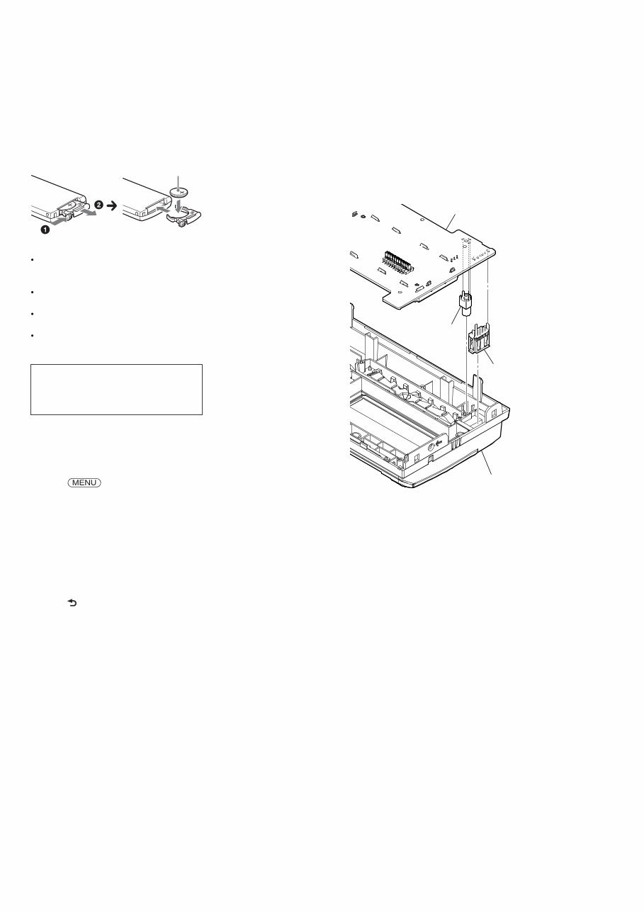
Never turn the semi-fixed resistor located at the side of optical
pick-up block.
optical pick-up
semi-fixed resistor
UNLEADED SOLDER
Boards requiring use of unleaded solder are printed with the lead-
free mark (LF) indicating the solder contains no lead.
(Caution: Some printed circuit boards may not come printed with
the lead free mark due to their particular size)
: LEAD FREE MARK
Unleaded solder has the following characteristics.
• Unleaded solder melts at a temperature about 40 °C higher
than ordinary solder.
Ordinary soldering irons can be used but the iron tip has to be
applied to the solder joint for a slightly longer time.
Soldering irons using a temperature regulator should be set to
about 350 °C.
Caution: The printed pattern (copper foil) may peel away if
the heated tip is applied for too long, so be careful!
• Strong viscosity
Unleaded solder is more viscous (sticky, less prone to flow)
than ordinary solder so use caution not to let solder bridges
occur such as on IC pins, etc.
• Usable with ordinary solder
It is best to use only unleaded solder but unleaded solder may
also be added to ordinary solder.
1. SERVICING NOTES ............................................. 3
2. GENERAL .................................................................. 9
3. DISASSEMBLY
3-1. Disassembly Flow ........................................................... 15
3-2. Mini Fuse (Blade Type) (10A/32V) (FU1), Cover ......... 16
3-3. Front Panel Block ........................................................... 16
3-4. CD Mechanism Deck (MG-101CA-188) ....................... 17
3-5. Connection Cable (MIC) (MJ1) ...................................... 17
3-6. MAIN Board (with BT Board) ....................................... 18
3-7. SERVO Board ................................................................. 18
3-8. Chassis (T) Sub Assy ...................................................... 19
3-9. Roller Arm Assy.............................................................. 19
3-10. Chassis (OP) Assy........................................................... 20
3-11. Chucking Arm Sub Assy ................................................. 20
3-12. Sled Motor Assy.............................................................. 21
3-13. Optical Pick-up Section .................................................. 22
3-14. Optical Pick-up ............................................................... 22
3-15. Knob................................................................................ 23
4. TEST MODE ............................................................ 24
5. DIAGRAMS
5-1. Block Diagram - SERVO Section - ................................ 25
5-2. Block Diagram - MAIN Section -................................... 26
5-3. Block Diagram
- PANEL/POWER SUPPLY Section - ............................ 27
5-4. Schematic Diagram - MAIN Section (1/5) - ................... 29
5-5. Schematic Diagram - MAIN Section (2/5) - ................... 30
5-6. Schematic Diagram - MAIN Section (3/5) - ................... 31
5-7. Schematic Diagram - MAIN Section (4/5) - ................... 32
5-8. Schematic Diagram - MAIN Section (5/5) - ................... 33
5-9. Printed Wiring Board - MAIN Section (1/2) - ................ 34
5-10. Printed Wiring Boards - MAIN Section (2/2) - .............. 35
5-11. Printed Wiring Board
- KEY Board (Component Side) -................................... 36
5-12. Printed Wiring Board
- KEY Board (Conductor Side) - .................................... 37
5-13. Schematic Diagram - KEY Board - ................................ 38
6. EXPLODED VIEWS
6-1. Main Section ................................................................... 49
6-2. Front Panel Section ......................................................... 50
6-3. CD Mechanism Deck Section (MG-101CA-188) .......... 51
7. ELECTRICAL PARTS LIST .............................. 52
Accessories are given in the last of the electrical parts list.
TABLE OF CONTENTS
NOTES ON HANDLING THE OPTICAL PICK-UP
BLOCK OR BASE UNIT
WX-GT90BT/GT90BTE/GT99BT
4
NOTE THE MAIN BOARD OR SYSTEM CONTROLLER
(IC501) REPLACING
When the MAIN board or system controller (IC501) is replaced,
the destination setting is necessary.
1. Prior Setting
It is necessary to set with the remote commander so that it can
operate by the main unit.
Setting method:
1. In the state of power on, press the buttons in order of the [4] t
[5] t [6] on the remote commander (press only the [6] button
for two seconds).
2. Press the buttons in order of the [ ] t [ ] t [ENTER] on
the remote commander.
Setting screen
12 digit
OP5 OP4 OP3 OP2 OP1 OP0
TP
3. Press the buttons in order of the [ENTER] (four times) t [ ]
t [ENTER] (two times) on the remote commander.
4. Setting is completed, and the unit returns to the state of source
off (the clock is displayed on the liquid crystal display).
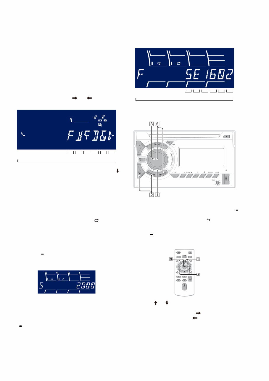
2. Destination Setting
Set destination according to the procedure below.
2-1. Setting the Destination Code
1. In the state of source off (the clock is displayed), enter the test
mode by pressing the buttons in order of the [ 4] t [MIC/
ZAP 5] t [PAUSE 6] (press only the [PAUSE 6] button for
two seconds).
2. In the state in which the system controller version is displayed
on the liquid crystal display (refer to following figure), enter
the destination setting mode by pressing the buttons in order
of the [M > SEEK+] t [SEEK– . m] t [PUSH EN-
TER/MENU/ APP].
(Displayed characters/values in the following figure are ex-
ample)
System controller version
3. Input the alphanumeric character of 12 digits of “F XXXXXX”
displayed on the liquid crystal display, and execute the destina-
tion setting.
Note: Refer to following “2-3. Entering the Destination Code” for opera-
tion method.
4. The resetting operation is executed by pressing the [SOURCE
OFF] button for 1 second after the setting ends, and the unit
returns to the normal condition.
2-2. Display in Destination Setting Mode
(Displayed characters/values in the following figure are example)
Destination code
12 digit
OP5 OP4 OP3 OP2 OP1 OP0
2-3. Entering the Destination Code
• Method of operation by main unit
1. Rotate the control dial, and select the alphanumeric character
of “0 to F”.
2. The digit advances by pressing the [PUSH ENTER/MENU/
APP] or [M > SEEK+] button.
The digit returns by pressing the [MODE ] or [SEEK– .
m] button.
3. The setting is completed by pressing the [PUSH ENTER/
MENU/ APP] button, and the initialization operation is done.
• Method of operation by remote commander
1. Press the [ ] or [ ] button, and select the alphanumeric char-
acter of “0 to F”.
2. The digit advances by pressing the [ ] button.
The digit returns by pressing the [ ] button.
3. The setting is completed by pressing the [ENTER] button, and
the initialization operation is done.
PTY 1 2 3 4 5 6
WX-GT90BT/GT90BTE/GT99BT
5
TEST DISCS
Use following TEST DISC (for CD) when this set confirms the
operation and checks it.
Part No. Description
3-702-101-01 DISC (YEDS-18), TEST
4-225-203-01 DISC (PATD-012), TEST
NOTE FOR REPLACEMENT OF THE BT BOARD
When repairing, the complete BT board should be replaced since
any parts in the BT board cannot be repaired.
NOTE FOR REPLACEMENT OF THE SERVO BOARD
When repairing, the complete SERVO board should be replaced
since any parts in the SERVO board cannot be repaired.
NOTE FOR REPLACEMENT OF THE SENSOR BOARD
When the SENSOR board is defective, exchange the MECHANI-
CAL BLOCK ASSY.
IMPORTANT NOTE OF “INITIALIZING”
The purpose of “Bluetooth Initialize” is to initialize the Bluetooth
connection history (HF/Audio Streaming). (To delete the device
information for the devices that you connected to when searching,
etc.)
When the complete BT board or complete MAIN board (including
BT board) are replaced, it is necessary to initialize this unit.
Refer to the following, initialize this unit.
Note: Phonebook data and dialed/received call history can be deleted by
executing “Reset.”
Initializing Bluetooth Settings
You can initialize all the Bluetooth related
settings (pairing information, preset
number, device information, etc.) from this
unit.
1 Press and hold for 1
second to turn off the power.
2 Press , rotate the control dial
until "BT" appears, then press it.
e menu lis t appears.
3 Rotate the control dial to select “BT
INIT,” then press it.
e confirmation ap pears.
4 Rotate the control dial to select “INIT-
YES,” then press it.
“INITIAL” flashes while initializing the
Bluetooth settings; “COMPLETE”
appears when initializing has finished.
5 Press (BACK) to return to the
previous display.
Note
When disposing of this unit, preset numbers
should be deleted with “BT INIT.”
NOTE ON CONNECTION
If speaker and amplifier are not connected correctly,
“FAILURE” appears in the display. In this case, make sure
the speaker and amplifier are connected correctly.
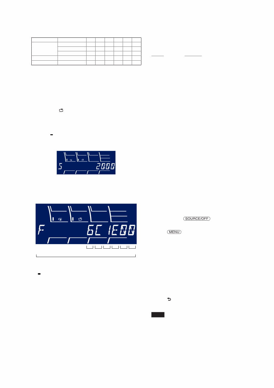
2-4. Destination Code
Model Destination OP5 OP4 OP3 OP2 OP1 OP0
WX-GT90BT
US, Canadian 5 E 1 6 0 2
AEP, UK 4 C 1 6 0 1
E 6 C 1 E 0 0
WX-GT90BTE Russian C C 1 6 2 7
WX-GT99BT Indian 6 C 1 E 1 0
3. Confirmation After Destination Setting
Execute the following operation after completing the destination
setting, and confirm a correct destination was set.
Destination setting checking method:
1. In the state of source off (the clock is displayed on the liquid
crystal display), enter the test mode by pressing the buttons in
order of the [ 4] t [MIC/ZAP 5] t [PAUSE 6] (press only
the [PAUSE 6] button for two seconds).
2. In the state in which the system controller version is displayed
on the liquid crystal display (refer to following figure), enter
the destination setting value display mode by pressing the
[DSPL SCRL] button three times.
(Displayed characters/values in the following figure are ex-
ample)
System controller version
3. Confirm the alphanumeric character of 12 digits in liquid crys-
tal display is an value correctly input.
(Displayed characters/values in the following figure are ex-
ample)
Destination code
12 digit
OP5 OP4 OP3 OP2 OP1 OP0
4. The resetting operation is executed by pressing the [SOURCE
OFF] button for 1 second after the confirming ends, and the
unit returns to the normal condition.
WX-GT90BT/GT90BTE/GT99BT
6
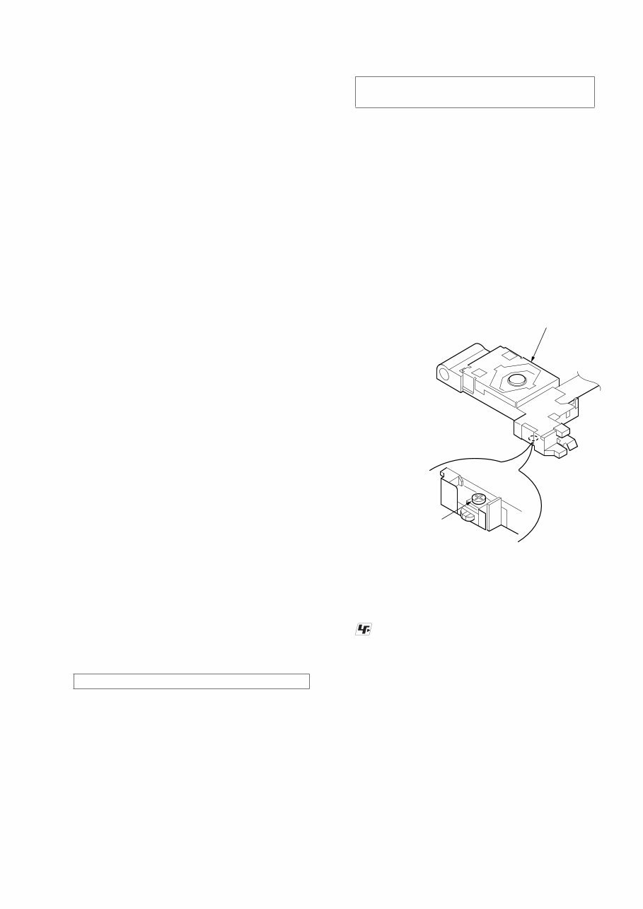
NOTE FOR REPLACEMENT OF THE USB CONNEC-
TOR (CN971) AND THE AUX JACK (J901)
To replace the USB connector and AUX jack requires alignment.
1. Insert the USB connector and AUX jack into the front panel.
2. Place the KEY board on the front panel and align the terminals
of the USB connector and AUX jack with the holes in the KEY
board.
3. Solder seven terminals of the connector and three terminals of
the jack.
KEY board
front panel
USB (socket)
connector
(CN971)
AUX jack
(J901)
REPLACING THE LITHIUM BATTERY
OF THE REMOTE COMMANDER
When the battery becomes weak, the range
of the remote commander becomes shorter.
Replace the battery with a new CR2025
lithium battery. Use of any other battery
may present a risk of fire or explosion.
Notes on the lithium battery
Keep the lithium battery out of the reach of
children. Should the battery be swallowed,
immediately consult a doctor.
Wipe the battery with a dry cloth to assure a
good contact.
Be sure to observe the correct polarity when
installing the battery.
Do not hold the battery with metallic tweezers,
otherwise a short-circuit may occur.
+ side up
WARNING
Battery may explode if mistreated.
Do not recharge, disassemble, or dispose
of in fire.
You can cancel the demonstration display
which appears while this unit is turned off.
1 Press , rotate the control dial
until “DISPLAY” appears, then press
it.
2 Rotate the control dial until “DEMO”
appears, then press it.
3 Rotate the control dial to select
“DEMO-OFF,” then press it.
e setting is complete.
4 Press (BACK) to return to the
previous display.
e display returns to normal reception/
play mode.
CANCELING THE DEMO MODE
WX-GT90BT/GT90BTE/GT99BT
7
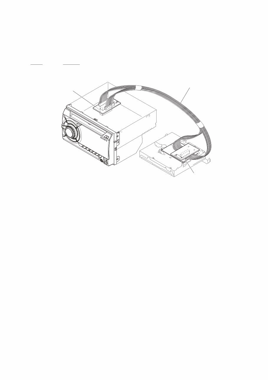
EXTENSION CABLE AND SERVICE POSITION
When repairing or servicing this set, connect the jig cable (extension cable (CD mecha)) as shown below.
• Connect the MAIN board (CN700) and the SERVO board (CN401) with the jig cable.
Jig cable:
Part No. Description
A-1818-424-A EXTENSION CABLE (CD MECHA)
SERVO board
(CN401)
MAIN board
(CN700)
extension cable (CD mecha)
WX-GT90BT/GT90BTE/GT99BT
8
6. Bluetooth Phone (Hands Free) Function Check
Note 1: Depending on the connecting device, Signal-strength/Battery-
remaining indications might not be displayed.
Or, depending on the connecting device, the levels of indications
are shown incorrectly.
Even if you see no indications or wrong indications, they are not
failures of WX-GT90BT/GT90BTE/GT99BT.
1. Search for this unit from the Bluetooth device (cellular phone),
and confirm whether this unit (“Sony Automotive”) is dis-
played.
2. Search for the distance of this unit and the Bluetooth device
(cellular phone) about 5 m apart.
Confirm whether the Bluetooth device (or this unit) is dis-
played after it searches.
3. Do the pairing of the cellular phone and this unit (input of
passkey).
4. Connect the cellular phone with this unit, and confirm the
“HF” icon ( ) lights.
5. Confirm the connection continues even if the distance of the
cellular phone and this unit is separated by about 5 m.
6. Set this unit besides the “BT PHONE” source, and call the cel-
lular phone connected with this unit.
Confirm the automatic change of this unit into “BT PHONE”
source, and the change into the screen for incoming calls.
Confirm the ring tone is heard from the front speaker.
7. Take a phone call (press the [CALL ] button), and start a
conversation.
Confirm the other person voice is heard from the speaker.
Speak toward an external microphone at the following condi-
tion, and confirm the other party hears its voice (An external
microphone is connected).
Compare the sound quality with a normal set. Confirm that
there is no big difference.
8. Turn on ACC from off, and confirm whether this set connects
Bluetooth with the cellular phone again.
Note 2: Depending on the cellular phone, it might not reconnect automati-
cally when ACC is turned on.
7. Bluetooth Audio Function Check
Note 1: Depending on the connecting BT Audio device, track information
(e.g. track name, playback time) can be on display.
If the device doesn’t support AVRCP1.3, or, if AVRCP1.3 fea-
ture of the device has not been validated with WX-GT90BT/GT-
90BTE/GT99BT, the track information won’t be shown.
Even if there is no track information on display during playback
of an AVRCP1.3 device, it is not a failure of WX-GT90BT/GT-
90BTE/GT99BT.
1. Connect the Bluetooth audio device (or cellular phone with
Bluetooth audio function) with this unit, and confirm the “Au-
dio Streaming” icon ( ) lights.
2. Playback Bluetooth audio. Confirm the sound is emitted from
this unit when this unit is switched to “Bluetooth Audio”
source.
3. Confirm whether Bluetooth audio can be controlled by oper-
ating this unit (the [SEEK+ > M], [m . SEEK–] and
[PAUSE 6] buttons operation).
Note 2: Varies depending on the connected Bluetooth audio device.
8. What to Do after Checking
• After checking, select “BT INIT” from the menu list of this
unit to execute initialization.
(Connected device information is deleted)
BLUETOOTH FUNCTION CHECKING METHOD USING
A CELLULAR PHONE
1. Required Equipment
• Set to be tested (WX-GT90BT/GT90BTE/GT99BT), external
microphone of attachment
• Cellular phone (Recommended SEMC W880 or W910i, or se-
lect from connectable cellular phones list)
• Bluetooth audio devices (SONY NWZ-A826, or select from
connectable cellular phones/audio devices list)
• Speaker connection (at least Front L/R ch)
• DC power supply (12 V)
2. Preparation
• Confirm the setting of the WX-GT90BT/GT90BTE/GT99BT,
and note down it.
• Press the [CALL ] button and rotate the control dial until
“SET PAIRING” appears, then press it, confirm that the Blue-
tooth signal icon ( ) is flashing.
• Turn on the Bluetooth function of the cellular phone.
3. Test Environment
• No other Bluetooth device is making a communication in the
periphery (within 20 m).
• No other WX-GT90BT/GT90BTE/GT99BT are supplied with
electric power.
• There are no two or more wireless LAN access points in the
periphery (with 50 m) (one is OK).
• The set should be tested in a place such as a meeting room, free
from ambient noise.
• The speaker at the far end should be in a place such as another
meeting room separated acoustically.
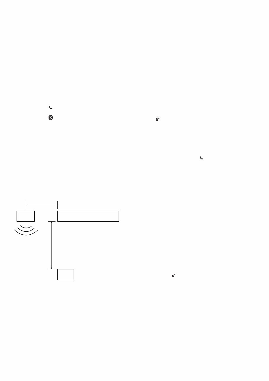
4. Setting
Install the WX-GT90BT/GT90BTE/GT99BT on the desktop.
Speaker
Approx. 50 cm
WX-GT90BT/GT90BTE/GT99BT
Tester
Approx. 80 cm
5. Precautions
Beware of the following points when conducting the
talking test:
• There is no fault if a talking can be made by adjusting appro-
priately the volume of the telephone of the other party and the
cellular phone connected through the Bluetooth, besides the
setup of WX-GT90BT/GT90BTE/GT99BT.
• The speaker’s voice will become loud naturally if the periph-
ery is noisy, or become low if quiet (even though the speaker
intents to talk on the same volume level).
• The speaker’s voice will become loud naturally if the other
party’s voice is loud.
WX-GT90BT/GT90BTE/GT99BT
9
SECTION 2
GENERAL
This section is extracted
from instruction manual.
(US and Canadian models)
Notes on speaker connection
Before connecting the speakers, turn the unit off.
Use speakers with an impedance of 4 to 8 ohms, and with adequate
power handling capacities to avoid its damage.
Do not connect the speaker terminals to the car chassis, or connect the
terminals of the right speakers with those of the left speaker.
Do not connect the ground (earth) lead of this unit to the negative (–)
terminal of the speaker.
Do not attempt to connect the speakers in parallel.
Connect only passive speakers. Connecting active speakers (with
built-in amplifiers) to the speaker terminals may damage the unit.
To avoid a malfunction, do not use the built-in speaker leads installed in
your car if the unit shares a common negative (–) lead for the right and
left speakers.
Do not connect the unit’s speaker leads to each other.
Note on connection
If speaker and amplifier are not connected correctly, “FAILURE” appears in
the display. In this case, make sure the speaker and amplifier are
connected correctly.
English
Cautions
Be sure to install this unit in the dashboard of the car as
the rear side of the unit becomes hot during use.
is unit is designed for negative ground (earth) 12 V
DC operation only.
Do not get the leads under a screw, or caught in moving
parts (e.g. seat railing).
Before making connections, turn the car ignition off to
avoid short circuits.
Connect the yellow and red power supply leads only
after all other leads have been connected.
Run all ground (earth) leads to a common ground
(earth) point.
Be sure to insulate any loose unconnected leads with
electrical tape for safety.
e use of optical instruments with this product will
increase eye hazard.
Notes on the power supply lead (yellow)
When connecting this unit in combination with other
stereo components, the connected car circuit’s rating
must be higher than the sum of each component’s fuse.
When no car circuits are rated high enough, connect the
unit directly to the battery.
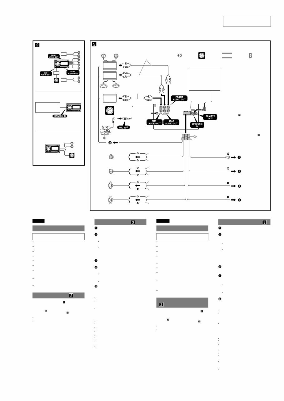
Connection example ( )
Subwoofer Direct Connection ( -C)
For details on the setting for the connection, see the
supplied Operating Instruction.
*1 not supplied ( -B)
*2 Do not connect a speaker in this connection ( -C).
Notes
Be sure to connect the ground (earth) lead before connecting the
amplifier.
The alarm will only sound if the built-in amplifier is used.
Français
Précautions
Installez cet appareil sur le tableau de bord de la voiture,
car l’arrière de l’appareil chauffe en cours d’utilisation.
Cet appareil est exclusivement conçu pour fonctionner
sur une tension de 12 V CC avec masse négative.
Évitez de fixer des vis sur les câbles ou de coincer ceux-ci
dans des pièces mobiles (par exemple, armature de siège).
Avant d’effectuer les raccordements, coupez le moteur
pour éviter un court-circuit.
Raccordez les câbles d’alimentation jaune et rouge
seulement après avoir terminé tous les autres
raccordements.
Rassemblez tous les câbles de mise à la masse en
un point de masse commun.
Pour des raisons de sécurité, veillez à isoler avec du
ruban isolant tout câble libre non raccordé.
L’utilisation d’instruments optiques avec ce produit
augmente les risques pour les yeux.
Remarques sur le câble d’alimentation (jaune)
Lorsque cet appareil est raccordé à d’autres éléments
stéréo, la valeur nominale du circuit de la voiture
raccordé doit être supérieure à la somme des fusibles de
chaque élément.
Si aucun circuit de la voiture n’est assez puissant,
raccordez directement l’appareil à la batterie.
Exemple de raccordement
( )
Raccordement direct d’un caisson de graves ( -C)
Pour plus de détails sur le réglage pour le raccordement,
reportez-vous au mode d’emploi fourni.
*1 non fourni ( -B)
*2 Ne raccordez pas un haut-parleur avec cette connexion ( -C).
Remarques
Raccordez d’abord le câble de mise à la masse avant de raccorder
l’amplificateur.
L’alarme est émise uniquement lorsque l’amplificateur intégré est utilisé.
Connection diagram ( )
To a metal surface of the car
First connect the black ground (earth) lead, then connect the yellow
and red power supply leads.
To the power antenna (aerial) control lead or
power supply lead of antenna (aerial) booster
Notes
It is not necessary to connect this lead if there is no power antenna
(aerial) or antenna (aerial) booster, or with a manually-operated
telescopic antenna (aerial).
When your car has a built-in FM/AM antenna (aerial) in the rear/
side glass, see “Notes on the control and power supply leads.”
To AMP REMOTE IN of an optional power
amplifier
This connection is only for amplifiers and a power antenna (aerial).
Connecting any other system may damage the unit.
To a car’s illumination signal
Be sure to connect the black ground (earth) lead to a metal surface of
the car first.
To the +12 V power terminal which is energized
in the accessory position of the ignition switch
Notes
If there is no accessory position, connect to the +12 V power
(battery) terminal which is energized at all times.
Be sure to connect the black ground (earth) lead to a metal surface
of the car first.
When your car has a built-in FM/AM antenna (aerial) in the rear/
side glass, see “Notes on the control and power supply leads.”
To the +12 V power terminal which is energized
at all times
Be sure to connect the black ground (earth) lead to a metal surface of
the car first.
Notes on the control and power supply leads
REM OUT lead (blue/white striped) supplies +12 V DC when you turn on
the unit.
When your car has built-in FM/AM antenna (aerial) in the rear/side
glass, connect REM OUT lead (blue/white striped) or the accessory
power supply lead (red) to the power terminal of the existing antenna
(aerial) booster. For details, consult your dealer.
A power antenna (aerial) without a relay box cannot be used with this
unit.
Memory hold connection
When the yellow power supply lead is connected, power will always be
supplied to the memory circuit even when the ignition switch is turned off.
Schéma de raccordement ( )
À un point métallique de la voiture
Branchez d’abord le câble de mise à la masse noir et, ensuite, les
câbles d’alimentation jaune et rouge.
Au câble de commande d’antenne électrique ou
au câble d’alimentation de l’amplificateur
d’antenne
Remarques
Il n’est pas nécessaire de raccorder ce câble s’il n’y a pas d’antenne
électrique ni d’amplificateur d’antenne, ou avec une antenne
télescopique manuelle.
Si votre voiture est équipée d’une antenne FM/AM intégrée dans la
vitre arrière/latérale, voir « Remarques sur les câbles de commande
et d’alimentation ».
Au niveau de AMP REMOTE IN de l’amplificateur
de puissance en option
Ce raccordement s’applique uniquement aux amplificateurs et à une
antenne électrique. Le branchement de tout autre système risque
d’endommager l’appareil.
Vers le connecteur du signal d’éclairage de la
voiture
Raccordez d’abord le câble de mise à la masse noir à un point
métallique du véhicule.
À la borne d’alimentation +12 V qui est alimentée
quand la clé de contact est sur la position
accessoires
Remarques
S’il n’y a pas de position accessoires, raccordez la borne
d’alimentation (batterie) +12 V qui est alimentée en permanence.
Raccordez d’abord le câble de mise à la masse noir à un point
métallique du véhicule.
Si votre voiture est équipée d’une antenne FM/AM intégrée dans la
vitre arrière/latérale, voir « Remarques sur les câbles de commande
et d’alimentation ».
À la borne d’alimentation +12 V qui est alimentée
en permanence
Raccordez d’abord le câble de mise à la masse noir à un point
métallique du véhicule.
Remarques sur les câbles de commande et d’alimentation
Le câble REM OUT (rayé bleu/blanc) fournit une alimentation de +12 V
CC lorsque vous mettez l’appareil en marche.
Lorsque votre voiture est équipée d’une antenne FM/AM intégrée dans
la vitre arrière/latérale, raccordez le câble REM OUT (rayé bleu/blanc) ou
le câble d’alimentation des accessoires (rouge) à la borne
d’alimentation de l’amplificateur d’antenne existant. Pour plus de
détails, consultez votre détaillant.
Une antenne électrique sans boîtier de relais ne peut pas être utilisée
avec cet appareil.
Raccordement pour la conservation de la mémoire
Lorsque le câble d’alimentation jaune est raccordé, le circuit de la
mémoire est alimenté en permanence même si la clé de contact est sur la
position d’arrêt.
Remarques sur le raccordement des haut-parleurs
Avant de raccorder les haut-parleurs, éteignez l'appareil.
Utilisez des haut-parleurs ayant une impédance de 4 à 8 ohms avec une
capacité électrique adéquate pour éviter de les endommager.
Ne raccordez pas les bornes du système de haut-parleurs au châssis de
la voiture et ne raccordez pas les bornes du haut-parleur droit à celles
du haut-parleur gauche.
Ne raccordez pas le câble de mise à la masse de cet appareil à la borne
négative (–) du haut-parleur.
N’essayez pas de raccorder les haut-parleurs en parallèle.
Raccordez uniquement des haut-parleurs passifs. Le raccordement de
haut-parleurs actifs (avec amplificateurs intégrés) aux bornes des
haut-parleurs peut endommager l’appareil.
Pour éviter tout problème de fonctionnement, n’utilisez pas les câbles
des haut-parleurs intégrés installés dans votre voiture si l’appareil
possède un câble négatif commun (–) pour les haut-parleurs droit et
gauche.
Ne raccordez pas entre eux les cables des haut-parleurs de l’appareil.
Remarque sur le raccordement
Si le haut-parleur et l’amplificateur ne sont pas raccordés correctement, le
message « FAILURE » s’affiche. Dans ce cas, assurez-vous que les
haut-parleurs et l’amplificateur sont bien raccordés.
A
*2
B
C
Satellite radio tuner
(SiriusXM)*1
Syntoniseur radio satellite
(SiriusXM)*1
Equipment used in illustrations (not supplied)
Appareils utilisés dans les illustrations (non fournis)
Front speaker
Haut-parleur avant
Subwoofer
Caisson de graves
Power amplifier
Amplificateur de puissance
*
1
*
1
REM OUT
Max. supply current 0.4 A
Courant max. fourni 0,4 A
Fuse (10 A)
Fusible (10 A)
Blue/white striped
Rayé bleu/blanc
ACC
BATTERY
White
Blanc
Green
Vert
Purple
Violet
White/black striped
Rayé blanc/noir
Gray/black striped
Rayé gris/noir
Green/black striped
Rayé vert/noir
Gray
Gris
Left
Gauche
Right
Droit
Left
Gauche
Right
Droit
Purple/black striped
Rayé violet/noir
from car antenna
(aerial)
à partir de l’antenne
du véhicule
Satellite radio tuner
(SiriusXM)*3
Syntoniseur radio satellite
(SiriusXM)*3
ILLUMINATION
*1 RCA pin cord (not supplied).
*2 Depending on the type of car, use an adaptor for a
wired remote control (not supplied).
*3 not supplied
*4 For details on installing the microphone, see “Installing
the microphone ( )” on the reverse side.
*5 Whether in use or not, route the microphone input cord
such that it does not interfere with driving. Secure the
cord with a clamp, etc., if it is installed around your feet.
*1 Cordon à broche RCA (non fourni).
*2 Selon le type de voiture, il pourrait être nécessaire
d’utiliser une télécommande câblée (non fournie).
*3 non fourni
*4 Pour les détails sur l’installation du microphone,
référez-vous à « Installation du microphone ( ) » au
verso.
*5 Qu’il soit en usage ou non, acheminez le cordon d’entrée
du microphone de telle sorte qu’il ne gêne pas votre
conduite. Fixez le cordon à l’aide d’une attache, etc., s’il
est installé autour de vos pieds.
Red
Rouge
Yellow
Jaune
Orange/white striped
Rayé orange/blanc
Black
Noir
Rear speaker
Haut-parleur arrière
*
4
WX-GT90BT/GT90BTE/GT99BT
10
Français
Précautions
Choisissez soigneusement l’emplacement d’installation
pour que l’appareil ne gêne pas le conducteur pendant la
conduite.
Évitez d’installer l’appareil dans un endroit exposé à la
poussière, à la saleté, à des vibrations excessives ou à des
températures élevées comme en plein soleil ou à
proximité de conduits de chauffage.
Pour garantir un montage sûr, n’utilisez que le matériel
fourni.
Réglage de l’angle de montage
Réglez l’inclinaison à un angle inférieur à 45°.
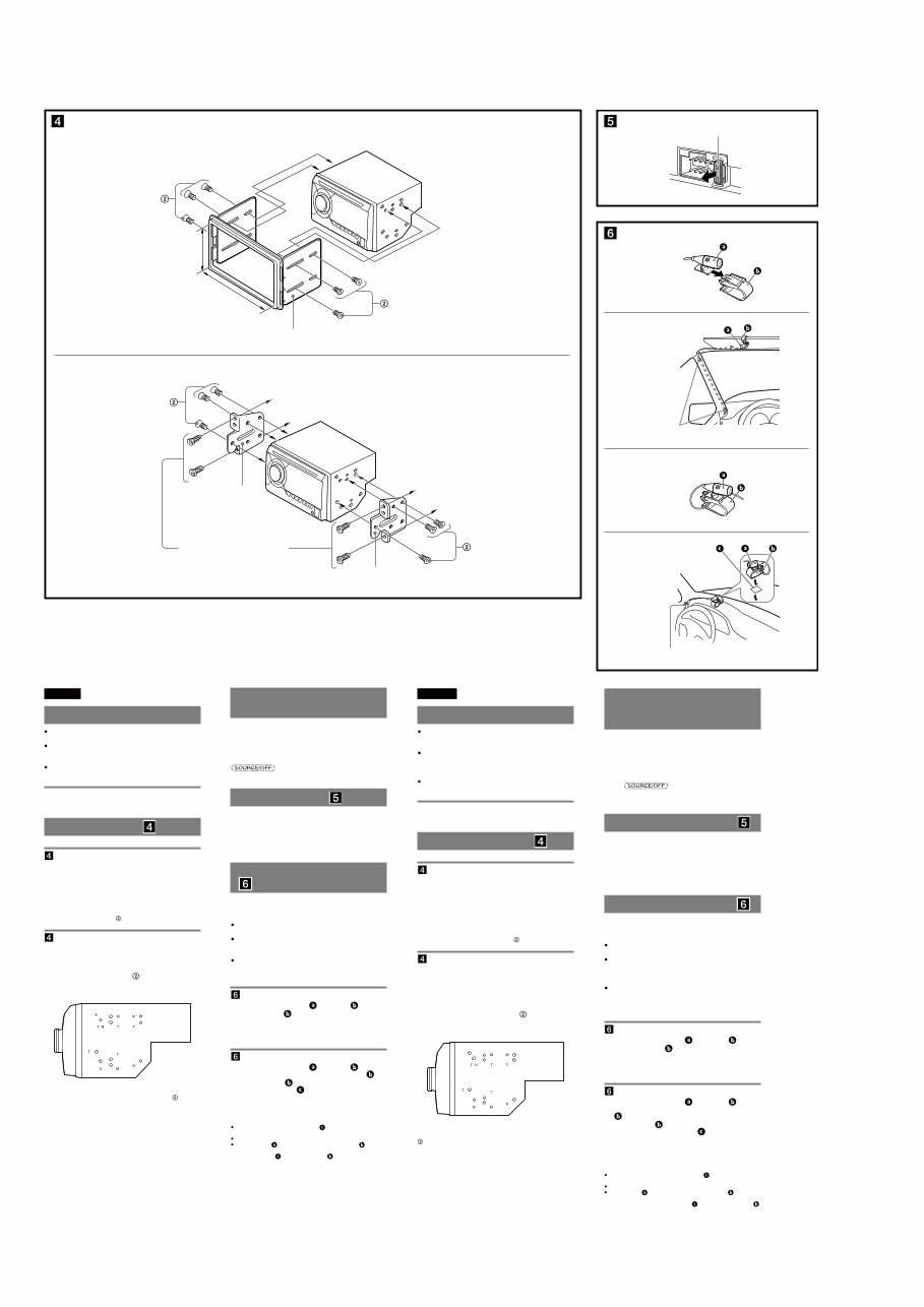
Montage de l’appareil ( )
-A Montage de l’appareil à l’aide d’un kit
d’installation (non fourni)
Vous pouvez utiliser un kit d’installation DIN double
disponible sur le marché. Choisissez un kit d’installation
dont la taille du cadre de la façade est la suivante :
Largeur minimale de 172 × 97 mm (6
7
/8 × 3
7
/8 po) (l/h),
avec un rayon d’arrondi interne inférieur à 0,5 mm
(
1
/32 po).
Remarque
Veillez à utiliser exclusivement les vis fournies .
-B Montage de l’appareil dans une
voiture japonaise
Cet appareil ne peut pas être installé dans certaines
voitures japonaises. Consultez, dans ce cas, votre détaillant
Sony.
Lors de la fixation de cet appareil dans les supports
pré-installés du véhicule, vissez les vis fournies dans les
trous appropriés selon le modèle de véhicule : T pour
TOYOTA, M pour MITSUBISHI et N pour NISSAN.
Remarque
Pour éviter tout problème de fonctionnement, utilisez uniquement les vis
fournies pour le montage.
Warning if your car’s ignition
has no ACC position
Be sure to set the Auto Off function. For details, see the
supplied Operating Instructions.
e unit will shut off completely and automatically in the
set time aſter the unit is turned off, which prevents battery
drain.
If you do not set the Auto Off function, press and hold
until the display disappears each time
you turn the ignition off.
Fuse replacement ( )
When replacing the fuse, be sure to use one matching the
amperage rating stated on the original fuse. If the fuse
blows, check the power connection and replace the fuse. If
the fuse blows again after replacement, there may be an
internal malfunction. In such a case, consult your nearest
Sony dealer.
Installing the microphone
( )
To capture your voice during handsfree calling, you need
to install the microphone (supplied).
Cautions
Keep the microphone away from extremely high
temperatures and humidity.
It is extremely dangerous if the cord becomes wound
around the steering column or gearstick. Be sure to keep
it and other parts from obstructing your driving.
If airbags or any other shock-absorbing equipment is in
your car, contact the store where you purchased this
unit, or the car dealer, before installation.
-A Installing on the sun visor
1 Install the microphone on the clip .
2 Install the clip on the sun visor.
3 Install clips (not supplied) and adjust the length
and position of the cord so that it does not
obstruct your driving.
-B Installing on the dashboard
1 Install the microphone on the clip , then
place the cord along the groove of the clip .
2 Attach the clip to the dashboard with the
double-sided tape .
3 Install a clip (not supplied) and adjust the length
and position of the cord so that it does not
obstruct your driving.
Notes
Before attaching the double-sided tape , clean the surface of the
dashboard with a dry cloth.
Adjust the microphone angle to the proper position.
The microphone can be installed without using the clip .
In this case, directly attach the microphone to the dashboard with the
double-sided tape . Keep the unused clip for future use.
Remarques
Avant de fixer le ruban adhésif à double face , nettoyez la surface du
tableau de bord avec un tissu sec.
Réglez l’angle du microphone à la bonne position.
Le microphone peut être installé sans utiliser la pince .
Le cas échéant, fixez directement le microphone au tableau de bord à
l’aide d’un ruban adhésif à double face . Gardez la pince inutilisée
pour utilisation ultérieure.
Avertissement si le contact de
votre véhicule ne comporte
pas de position ACC
Veillez à régler la fonction Auto Off. Pour obtenir
davantage d’informations, reportez-vous au mode d’emploi
fourni.
L’appareil s’éteint complètement et automatiquement après
le laps de temps choisi une fois l’appareil arrêté afin d’éviter
que la batterie ne se décharge.
Si vous ne réglez pas la fonction Auto Off, appuyez sur la
touche et maintenez-la enfoncée jusqu’à
ce que l’affichage disparaisse à chaque fois que vous
coupez le contact.
Remplacement du fusible ( )
Lorsque vous remplacez le fusible, veillez à utiliser un
fusible dont l’intensité, en ampères, correspond à la valeur
indiquée sur le fusible usagé. Si le fusible grille, vérifiez le
branchement de l’alimentation et remplacez le fusible. Si le
nouveau fusible grille également, il est possible que
l’appareil soit défectueux. Dans ce cas, consultez votre
détaillant Sony le plus proche.
Installation du microphone ( )
Pour capturer votre voix au cours d’un appel en mains
libres, vous devez installer le microphone (fourni).
Avertissements
Éloignez le microphone de l’humidité et des
températures extrêmement élevées.
Il est extrêmement dangereux que le cordon s'enroule
autour de la colonne de direction ou du levier de
vitesses. Assurez-vous d’éviter que le cordon et les autres
parties puissent encombrer votre conduite.
Si des coussins gonflables ou tout équipement antichoc
se trouvent dans votre voiture, communiquez avec le
magasin où vous avez acheté cet appareil, ou le
concessionnaire, avant l’installation.
-A Installation sur le pare-soleil
1 Installez le microphone sur la pince .
2 Installez la pince sur le pare-soleil.
3 Installez les pinces (non fournies) et réglez la
longueur et la position du cordon de façon à ne
pas encombrer votre conduite.
-B Installation sur le tableau de bord
1 Installez le microphone sur la pince , puis
placez le cordon le long de la rainure de la pince
.
2 Fixez la pince au tableau de bord à l’aide d’un
ruban adhésif à double face .
3 Installez la pince (non fournie) et réglez la
longueur et la position du cordon de façon à ne
pas encombrer votre conduite.
English
Precautions
Choose the installation location carefully so that the unit
will not interfere with normal driving operations.
Avoid installing the unit in areas subject to dust, dirt,
excessive vibration, or high temperatures, such as in
direct sunlight or near heater ducts.
Use only the supplied mounting hardware for a safe and
secure installation.
Mounting angle adjustment
Adjust the mounting angle to less than 45°.
Mounting the unit ( )
-A Mounting the unit with an installation
kit (not supplied)
You can use a commercially available double DIN
installation kit. Choose an installation kit with the
following panel frame size.
Larger than 172 × 97 mm (6
7
/8 × 3
7
/8 in) (w/h), with an
inner corner radius of less than 0.5 mm (
1
/32 in).
Note
Be sure to use the supplied screws .
-B Mounting the unit in a Japanese car
You may not be able to install this unit in some makes of
Japanese cars. In such a case, consult your Sony dealer.
When mounting this unit to the preinstalled brackets of
your car, use the supplied screws in the appropriate
screw holes, based on your car: T for TOYOTA, M for
MITSUBISHI and N for NISSAN.
Note
To prevent malfunction, install only with the supplied screws .
Bracket
Support
Bracket
Support
to dashboard/center console
vers le tableau de bord/la console centrale
Existing parts supplied with your car
Pièces existantes fournies avec la voiture
size
5 × max. 8 mm
(7/32 × max. 5/16 in)
dimension
5 × max. 8 mm
(7/32 × 5/16 po max.)
size
5 × max. 8 mm
(7/32 × max. 5/16 in)
dimension
5 × max. 8 mm
(7/32 × 5/16 po max.)
Fuse (10 A)
Fusible (10 A)
B
To dashboard/center console
Vers le tableau de bord/la console centrale
Installation kit (not supplied)
Kit d’installation (non fourni)
Larger than
97 mm (3 7/8 in)
Largeur minimale
de 97 mm (3 7/8 po)
Larger than
172 mm (6 7/8 in)
Largeur minimale de
172 mm (6 7/8 po)
A
2
Clip (not supplied)
Pince (non fournie)
A
2
1
Clips (not supplied)
Pinces (non fournies)
B
1
You're Reading a Preview
What's Included?
Fast Download Speeds
Online & Offline Access
Access PDF Contents & Bookmarks
Full Search Facility
Print one or all pages of your manual
$33.99
Sony WX-GT90BT/GT90BTE/GT99BT OEM Service & Repair Manual
Viewed 42 Times Today

What's Included?
Fast Download Speeds
Online & Offline Access
Access PDF Contents & Bookmarks
Full Search Facility
Print one or all pages of your manual
$33.99

Secure transaction
What's Included?
Fast Download Speeds
Online & Offline Access
Access PDF Contents & Bookmarks
Full Search Facility
Print one or all pages of your manual
Description
This OEM service and repair manual for the Sony WX-GT90BT/GT90BTE/GT99BT models provides comprehensive information for servicing and repairing these specific models. It offers detailed servicing notes, general information, disassembly instructions, test mode details, diagrams, exploded views, and an electrical parts list.
Features:
- Detailed servicing and repair instructions for Sony WX-GT90BT/GT90BTE/GT99BT models
- Step-by-step disassembly and test mode details
- Comprehensive diagrams and exploded views for easy reference
- Complete electrical parts list
- Presented in English
- Compatible with both Windows and Mac platforms


