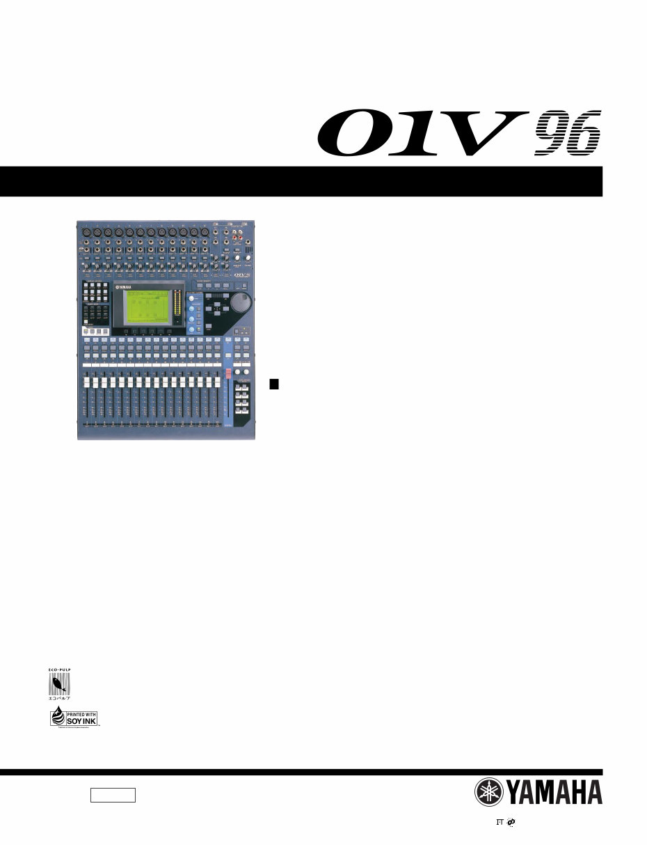
Yamaha 01V96 01-V96 01V-96 complete service manual
What's Included?
Lifetime Access
Fast Download Speeds
Online & Offline Access
Access PDF Contents & Bookmarks
Full Search Facility
Print one or all pages of your manual
01V96 1 SERVICE MANUAL PA 011680 1.329K-1933 Printed in Japan ’03.03 HAMAMATSU, JAPAN CONTENTS SPECIFICATIONS ................................................... 4 DIMENSIONS .......................................................... 12 PANEL LAYOUT .................................. 13 CIRCUIT BOARD LAYOUT ............... 21 DISASSEMBLY PROCEDURE ............................ 23 INSTALLING AN OPTIONAL CARD ............................................ 32 LSI PIN DESCRIPTION ................................ 33 IC BLOCK DIAGRAM .................................. 41 CIRCUIT BOARDS ....................................... 46 INSPECTIONS ....................................................... 76/83 SERVICE CHECK PROGRAM ... 90/102 INITIALIZING THE 01V96 ....................... 114 TRANSMITTING PARAMETER SETTINGS VIA MIDI (BULK DUMP) .... 115/117 CHECKING THE BATTERY AND THE SYSTEM VERSION .......... 119 CALIBRATING THE FADERS ................................... 119 MIDI DATA FORMAT ............... 120 MIDI IMPLEMENTATION CHART ............................ 134 PARTS LIST BLOCK DIAGRAM OVERALL CONNECTOR CIRCUIT DIAGRAM CIRCUIT DIAGRAM This document is printed on chlorine free (ECF) paper with soy ink. DIGITAL MIXING CONSOLE 200304-250000 (目次) (総合仕様) (寸法図) (パネルレイアウト) (ユニットレイアウト) (分解手順) (オプションカードの取り付け) (LSI端子機能表) (ICブロック図) (シート基板図) (検査) (サービス検査プログラム) (01V96の初期化) (内部設定をMIDI経由で出力(バルクダンプ機能)) (バッテリーの残量やシステムのバージョンの確認) (フェーダーのキャリブレーション) (MIDIデータフォーマット) (MIDIインプリメンテーションチャート) (ブロックダイアグラム) (総コネクタ接続回路図) (回路図) このサービスマニュアルはエコパルプ (ECF:無塩素系漂白パルプ)を使用しています。 このサービスマニュアルは大豆油 インクで印刷しています。
01V96 2 IMPORTANT NOTICE This manual has been provided for the use of authorized Yamaha Retailers and their service personnel. It has been assumed that basic service procedures inherent to the industry, and more specifically Yamaha Products, are already known and under- stood by the users, and have therefore not been restated. WARNING : Failure to follow appropriate service and safety procedures when servicing this product may result in per- sonal injury, destruction of expensive components and failure of the product to perform as specified. For these reasons, we advise all Yamaha product owners that all service required should be performed by an authorized Yamaha Retailer or the appointed service representative. IMPORTANT : This presentation or sale of this manual to any individual or firm does not constitute authorization certifi- cation, recognition of any applicable technical capabilities, or establish a principal-agent relationship of any form. The data provided is belived to be accurate and applicable to the unit(s) indicated on the cover. The research engineering, and service departments of Yamaha are continually striving to improve Yamaha products. Modifications are, therefore, inevitable and changes in specification are subject to change without notice or obligation to retrofit. Should any discrepancy appear to exist, please contact the distributor’s Service Division. WARNING : Static discharges can destroy expensive components. Discharge any static electricity your body may have accumulated by grounding yourself to the ground bus in the unit (heavy gauge black wires connect to this bus.) IMPORTANT : Turn the unit OFF during disassembly and parts replacement. Recheck all work before you apply power to the unit. WARNING: CHEMICAL CONTENT NOTICE! The solder used in the production of this product contains LEAD. In addition, other electrical/electronic and/or plastic (Where applicable) components may also contain traces of chemicals found by the California Health and Welfare Agency (and possibly other entities) to cause cancer and/or birth defects or other reproductive harm. DO NOT PLACE SOLDER, ELECTRICAL/ELECTRONIC OR PLASTIC COMPONENTS IN YOUR MOUTH FOR ANY REASON WHAT SO EVER! Avoid prolonged, unprotected contact between solder and your skin! When soldering, do not inhale solder fumes or expose eyes to solder/flux vapor! If you come in contact with solder or components located inside the enclosure of this product, wash your hands before handling food. WARNING Components having special characteristics are marked and must be replaced with parts having specification equal to those originally installed. WARNING: THIS APPARATUS MUST BE EARTHED IMPORTANT THE WIRES IN THIS MAINS LEAD ARE COLOURED IN ACCORDANCE WITH THE FOLLOWING CODE: GREEN-AND-YELLOW : EARTH BLUE : NEUTRAL BROWN : LIVE As the colours of the wires in the mains lead of this apparatus may not correspond with the coloured markings identifying the terminals in your plug, proceed as follows: The wire which is coloured GREEN and YELLOW must be connected to the terminal in the plug which is marked by the letter E or by the safety earth symbol or coloured GREEN and YELLOW. The wire which is coloured BLUE must be connected to the terminal which is marked with the letter N or coloured BLACK. The wire which is coloured BROWN must be connected to the terminal which is marked with the letter L or coloured RED. * This applies only to products distributed by YAMAHA KEMBLE MUSIC (U.K.) LTD. 印の商品は、安全を維持するために重要な部品です。交換する場合は、安全のために必ず指定の部品をご使用下さい。
01V96 3 Take care not to trap your fingers. LITHIUM BATTERY HANDLING This product uses a lithium battery for memory back-up. WARNING : Lithium batteries are dangerous because they can be exploded by improper handling. Observe the following pre- cautions when handling or replacing lithium batteries. Leave lithium battery replacement to qualified service personnel. Always replace with batteries of the same type. When installing on the PC board by soldering, solder using the connection terminals provided on the battery cells. Never solder directly to the cells. Perform the soldering as quickly as possible. Never reverse the battery polarities when installing. Do not short the batteries. Do not attempt to recharge these batteries. Do not disasemble the batteries. Never heat batteries or throw them into fire. ADVARSEL! Lithiumbatteri-Eksplosionsfare ved fejlagtig handtering. Udskiftning ma kun ske med batteri af samme fabrikat og type. lever det brugte batteri tilbage til leverandren. VARNING Explosionsfara vid felaktigt batteribyte. Anvand samma batterityp eller en ekvivalent typ som rekommenderas av apparattillverkaren. Kassera anvant batteri enligt fabrikantens instruktion. VAROITUS Paristo voi rajahtaa, jos se on virheellisesti asennettu. Vaihda paristo ainoastaan laitevalmistajan suosittelemaan tyyppiiin. Havita kaytetty paristo valmistajan ohjeiden mukaisesti. The following information complies with Dutch official Gazette 1995. 45; ESSENTIALS OF ORDER ON THE COLLECTION OF BATTERIES. • Please refer to the diassembly procedure for the removal of Back-up Battery. • Leest u voor het verwijderen van de backup batterij deze beschrijving. リチウム電池の取り扱い <注意> リチウム電池を誤って交換すると爆発する危険があります。交換する場合は、サービスマニュアルで指定された部品を 使用してください。 (作業中は指を挟まない様に注意して下さい。)
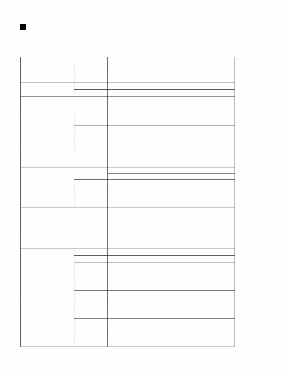
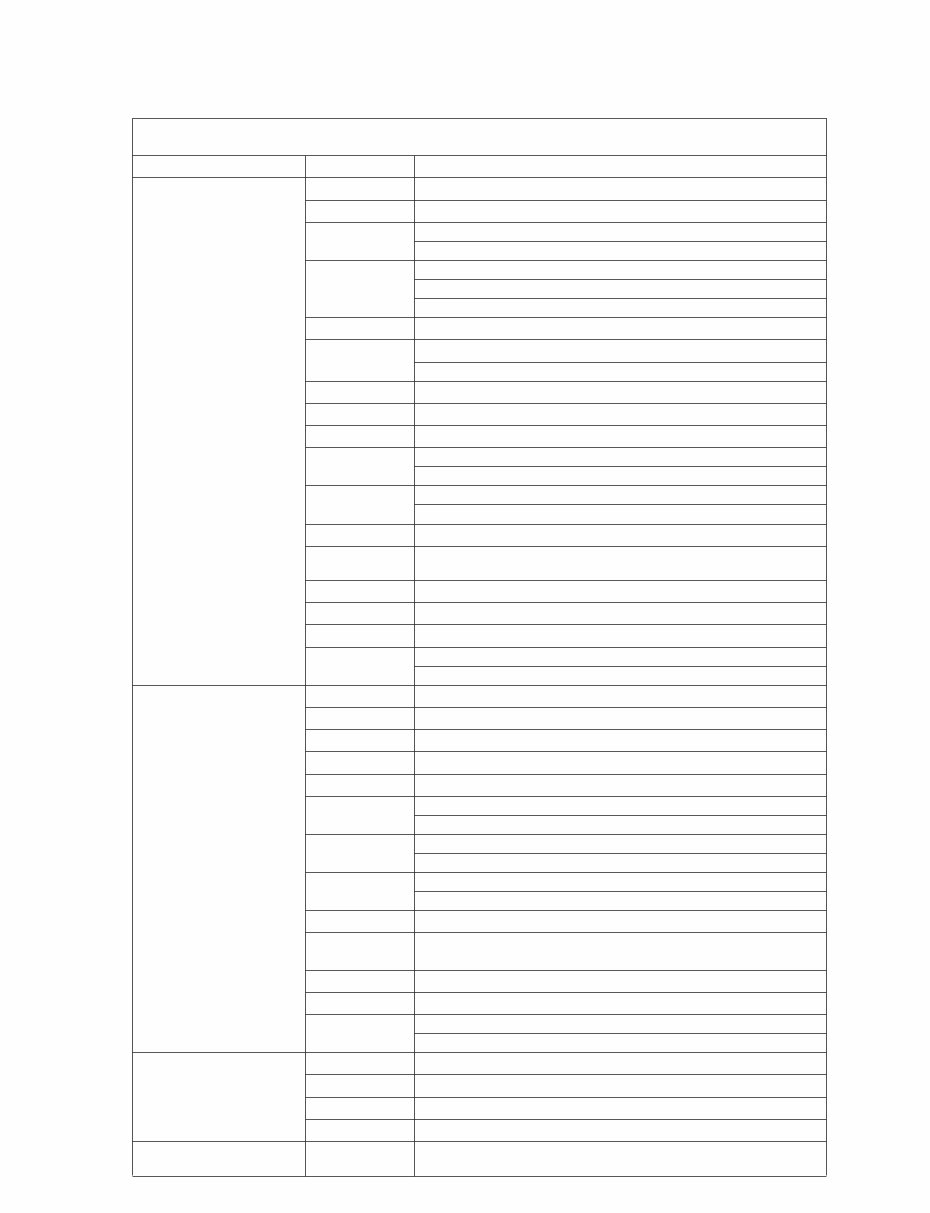
01V96 4 SPECIFICATIONS General Spec Number of scene memories 99 Sampling Frequency Internal 44.1 kHz, 48 kHz, 88.2 kHz, 96 kHz External Normal rate: 44.1 kHz–10% to 48 kHz+6% Double rate: 88.2 kHz–10% to 96 kHz+6% Signal Delay fs=48 kHz Less than 1.6 ms CH INPUT to STEREO OUT fs=96 kHz Less than 0.8 ms CH INPUT to STEREO OUT Fader 100 mm motorized with touch sense × 17 Fader Resolution +10 to –138, – ∞dB input faders 0 to –138, – ∞dB master faders, stereo fader Total Harmonic Distortion *1 (CH INPUT to STEREO OUT) (Input Gain=Min.) fs=48 kHz Less than 0.05% 20 Hz–20 kHz @ +14 dB into 600 Ω Less than 0.01% 1 kHz @ +24 dB into 600 Ω fs=96 kHz Less than 0.05% 20 Hz–40 kHz @ +14 dB into 600 Ω Less than 0.01% 1 kHz @ +24 dB into 600 Ω Frequency Response (CH INPUT to STEREO OUT) fs=48 kHz 20 Hz–20 kHz, 0.5, –1.5 dB @ +4 dB into 600 Ω fs=96 kHz 20 Hz–40 kHz, 0.5, –1.5 dB @ +4 dB into 600 Ω Dynamic Range (maximum level to noise level) 110 dB typ. DA Converter (STEREO OUT) 105 dB typ. AD+DA (to STEREO OUT) @ fs=48 kHz 105 dB typ. AD+DA (to STEREO OUT) @ fs=96 kHz Hum & Noise *2 (20 Hz–20 kHz) Rs=150 Ω –128 dB Equivalent Input Noise –86 dB residual output noise. STEREO OUT (STEREO OUT off) Input Gain=Max. Input Pad =0 dB –86 dB (90 dB S/N) STEREO OUT (STEREO fader at nominal level and all CH INPUT faders at minimum level) Input Pad =0 dB Input Sensitivity =–60 dB –64 dB (68 dB S/N) STEREO OUT (STEREO fader at nominal level and one CH INPUT fader at nominal level) Maximum Voltage Gain 74 dB CH INPUT (CH1–12) to STEREO OUT/OMNI (BUS) OUT 40 dB CH INPUT (CH13–16) to STEREO OUT 74 dB CH INPUT (CH1–12) to OMNI (AUX) OUT (via pre input fader) 74 dB CH INPUT (CH1–12) to MONITOR OUT (via STEREO BUS) Crosstalk (@ 1 kHz) Input Gain=Min. 80 dB adjacent input channels (CH1–12) 80 dB adjacent input channels (CH13–16) 80 dB input to output AD Input (1–12) Phantom switch +48 V DC (each 4ch) Pad switch 0/20 dB attenuation Gain control 44 dB (–60 to –16), detented Peak indicator LED (red) turns on when post HA level reaches 3 dB below clipping at dig- ital domain Signal indicator LED (green) turns on when post HA level reaches 20 dB below nominal at digital domain AD converter 24-bit linear, 128-times oversampling (fs=44.1, 48 kHz), 64-times over- sampling (fs=88.2, 96 kHz) AD Input (13–16) Gain control 30 dB (–26 to +4), detented Peak indicator LED (red) turns on when post HA level reaches 3 dB below clipping at dig- ital domain Signal indicator LED (green) turns on when post HA level reaches 20 dB below nominal at digital domain AD converter 24-bit linear, 128-times oversampling (fs=44.1, 48 kHz), 64-times over- sampling (fs=88.2, 96 kHz) Input selector CH15/16/2TR IN for CH15/16 (総合仕様) (一般仕様)
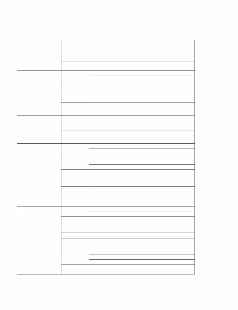
01V96 5 Digital Input (2TR IN DIGITAL, ADAT input) Option Input (SLOT) Available cards Optional digital interface cards (MY16, MY8, MY4 series) Input Channel CH1–32 Input patch — Phase Normal/reverse Gate-type *3 On/off Key in: 12 ch Group (1–12, 13–24, 25–32)/AUX1–8 Comp-type *4 On/off Key in: self /Stereo Link Pre EQ/pre fader/post fader Attenuator –96.0 to +12.0 dB (0.1 dB step) EQ 4-band PEQ (TYPE1) *5 On/off Delay 0–43400 samples On/off — Fader 100 mm motorized (INPUT/AUX1–8) Aux send On/off AUX1–8; pre fader/post fader Solo On/off Pre fader/after pan Pan 127 positions (Left= 1–63, Center, Right= 1–63) Surround pan 127 × 127 positions [(Left= 1–63, Center, Right= 1–63)], [(Front= 1–63, Center, Rear= 1–63)] LFE level –∞, –96 dB to +10 dB (256 step) Routing STEREO, BUS1–8, DIRECT OUT Direct out Pre EQ/pre fader/post fader Metering Displayed on LCD Peak hold on/off Stereo Input Channel CH1–4 Input patch (L/R) — Phase (L/R) Normal/reverse Attenuator (L/R) –96.0 to +12.0 dB (0.1 dB step) Equalizer 4band PEQ (TYPE1) *5 On/off — Fader 100 mm motorized INPUT/AUX1–8 send Aux send On/off AUX1–8; pre fader/post fader Solo On/off Pre fader/after pan Pan (L/R) 127 positions (Left= 1–63, Center, Right= 1–63) Surround pan (L/R) 127 × 127 positions ([Left= 1–63, Center, Right= 1–63] x [Front= 1–63, Center, Rear= 1–63]) LFE level (L/R) –∞, –96 dB to +10 dB (256 step) Routing STEREO, BUS1–8, DIRECT OUT Metering Displayed on LCD Peak hold on/off OSCILLATOR Level 0 to –96 dB (1 dB step) On/off — Waveform Sine 100 Hz, sine 1 kHz, sine 10 kHz, pink noise, burst noise Routing BUS1–8, AUX1–8, STEREO L/R STEREO OUT DA converter 24-bit linear, 128-times oversampling (@fs=44.1, 48 kHz), 64-times over- sampling (@fs=88.2, 96 kHz)
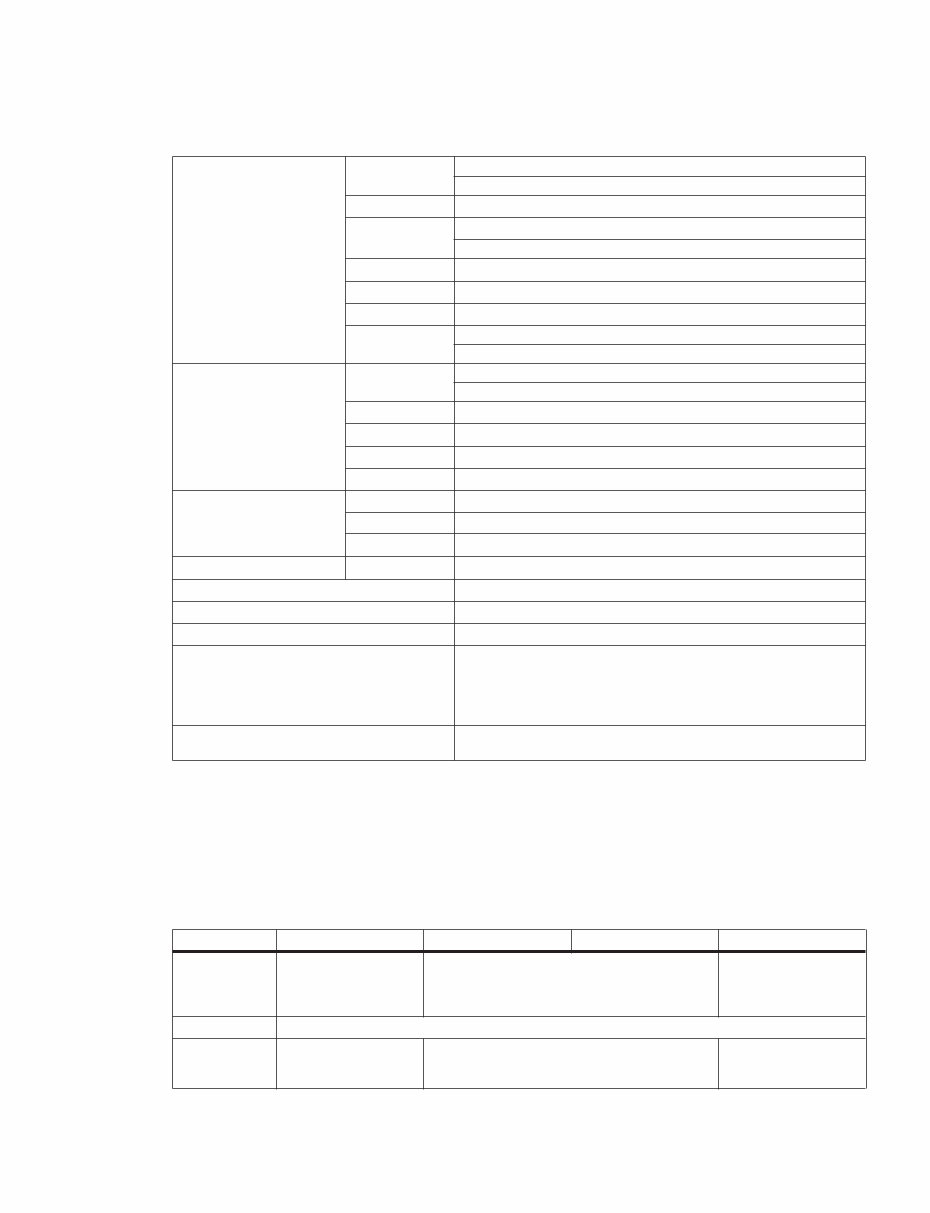
01V96 6 MONITOR OUT DA converter 24-bit linear, 128-times oversampling (@fs=44.1, 48 kHz), 64-times over- sampling (@fs=88.2, 96 kHz) OMNI OUT 1–4 Output patch STEREO, BUS1–8, AUX1–8, DIRECT OUT 1–32, INSERT OUT (CH1–32, BUS1–8, AUX1–8, STEREO), CASCADE OUT (BUS1–8, AUX 1–8, STEREO, SOLO) DA converter 24-bit linear, 128-times oversampling (@fs=44.1, 48 kHz), 64-times over- sampling (@fs=88.2, 96 kHz) 2TR OUT DIGITAL Dither On/off Word length 16, 20, 24-bit Output patch STEREO, BUS1–8, AUX 1–8, DIRECT OUT 1–32, INSERT OUT (CH 1–32, BUS 1–8, AUX 1–8, STEREO), CASCADE OUT (BUS 1–8, AUX 1–8, STEREO, SOLO) ADAT Output Dither On/off Word length 16, 20, 24-bit Output patch STEREO, BUS1–8, AUX 1–8, DIRECT OUT 1–32, INSERT OUT (CH 1–32, BUS 1–8, AUX 1–8, STEREO), CASCADE OUT (BUS 1–8, AUX 1–8, STEREO, SOLO) Option Output (SLOT) Available card Optional digital interface card (MY16, MY8, MY4 series) Dither On/off Word length 16/20/24-bit Output patch STEREO, BUS1–8, AUX 1–8, DIRECT OUT 1–32, INSERT OUT (CH 1–32, BUS 1–8, AUX 1–8, STEREO), CASCADE OUT (BUS 1–8, AUX 1–8, STEREO, SOLO) STEREO Comp-type *4 On/off Pre EQ/pre fader/post fader Attenuator –96.0 to +12.0 dB (0.1 dB step) EQ 4-band PEQ *5 On/off On/off — Fader 100 mm motorized Balance 127 positions (Left=1–63, Center, Right=1–63) Delay 0–29100 samples Metering Displayed on LCD Peak hold on/off 12-elements x2 LED meters BUS1–8 Comp-type *4 On/off Pre EQ/pre fader/post fader Attenuator –96.0 to +12.0 dB (0.1 dB step) EQ 4-band PEQ *5 On/off On/off — Fader 100 mm motorized Delay 0–29100 samples Bus to stereo Level (–∞, –130 dB–0 dB) On/off Pan: 127 positions (Left=1–63, Center, Right=1–63) Metering Displayed on LCD Peak hold on/off
01V96 7 AUX1–8 Comp-type *4 On/off Pre EQ/pre fader/post fader Attenuator –96.0 to +12.0 dB (0.1 dB step) EQ 4-band PEQ *5 On/off On/off — Fader 100 mm motorized Delay 0–29100 samples Metering Displayed on LCD Peak hold on/off INTERNAL EFFECTS (EFFECT 1–4) Number of effects 4@44.1kHz, 48kHz 2@88.2kHz, 96kHz Bypass On/off In/out 2-in, 2-out Effect-in from AUX1–8/INSERT OUT Effect-out to Japan U.S/Canada Others Input patch Power Requirements 100 V, 50/60 Hz 90 W 120 V, 60 Hz 90 W 220-240 V, 50/60 Hz 90 W Dimensions (H x D x W) 150 x 548 x 436 mm Net weight 15 kg Operating free-air temperature range 10–35°C Storage temperature range –20–60°C Supplied Accessories AC Cable (3P/2P AC plug adapter) CD-ROM (Studio Manager) Owner’s Manual Studio Manager Installation Guide Options Digital interface card (MY16, MY8, MY4 series) RACK MOUNT KIT: RK1 *1. Total harmonic distortion is measured with a 6 dB/octave filter @ 80 kHz. *2. Hum & Noise are measured with a 6 dB/octave filter @ 12.7 kHz; equivalent to a 20 kHz filter with infinite dB/octave attenuation. *3. See “Gate Parameters” on page 8. *4. See “Comp Parameters” on page 8. *5. See “EQ Parameters” on page 7. LOW/HPF L-MID H-MID HIGH /LPF Q 0.1–10.0 (41 points) low shelving HPF 0.1–10.0 (41 points) 0.1–10.0 (41 points) high shelving LPF F 20 Hz–20 kHz (1/12 oct step) G ±18 dB (0.1 dB step) HPF: on/off ±18 dB (0.1 dB step) ±18 dB (0.1 dB step) LPF: on/off Warranty card (J) EQ Parameters (EQ パラメーター)
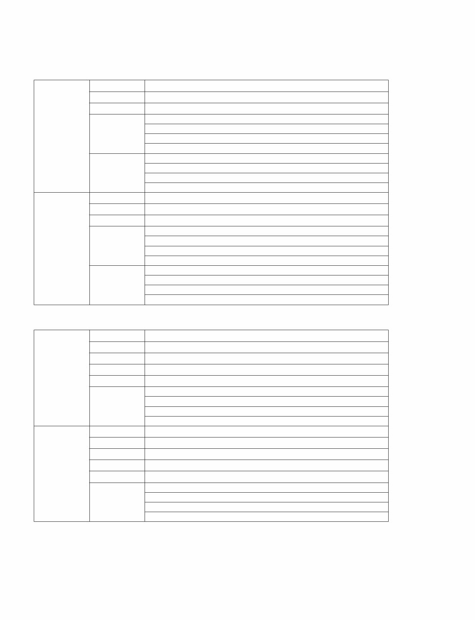
01V96 8 Gate Threshold –54 dB–0 dB (0.1 dB step) Range –70 dB–0 dB (1 dB step) Attack 0 ms–120 ms (1 ms step) Hold 0.02 ms–1.96 s (216 points) @ 48 kHz 0.02 ms–2.13 s (216 points) @ 44.1 kHz 0.01 ms–981 ms (216 points) @ 96 kHz 0.01 ms–1.06 s (216 points) @ 88.2 kHz Decay 5 ms–42.3 s (160 points) @ 48 kHz 6 ms–46.0 s (160 points) @ 44.1 kHz 3 ms–21.1 s (160 points) @ 96 kHz 3 ms–23.0 s (160 points) @ 88.2 kHz Ducking Threshold –54 dB–0 dB (0.1 dB step) Range –70 dB–0 dB (1 dB step) Attack 0 ms–120 ms (1 ms step) Hold 0.02 ms–1.96 s (216 points) @ 48 kHz 0.02 ms–2.13 s (216 points) @ 44.1 kHz 0.01 ms–981 ms (216 points) @ 96 kHz 0.01 ms–1.06 s (216 points) @ 88.2 kHz Decay 5 ms–42.3 s (160 points) @ 48 kHz 6 ms–46.0 s (160 points) @ 44.1 kHz 3 ms–21.1 s (160 points) @ 96 kHz 3 ms–23.0 s (160 points) @ 88.2 kHz Compressor Threshold –54 dB–0 dB (0.1 dB step) Ratio (x :1) x=1, 1.1, 1.3, 1.5, 1.7, 2, 2.5, 3, 3.5, 4, 5, 6, 8, 10, 20, ∞ (16 points) Out gain 0 dB to +18 dB (0.1 dB step) Knee Hard, 1, 2, 3, 4, 5 (6 step) Attack 0 ms–120 ms (1 ms step) Release 5 ms–42.3 s (160 points) @ 48 kHz 6 ms–46.0 s (160 points) @ 44.1 kHz 3 ms–21.1 s (160 points) @ 96 kHz 3 ms–23.0 s (160 points) @ 88.2 kHz Expander Threshold –54 dB to 0 dB (0.1 dB step) Ratio (x :1) x=1, 1.1, 1.3, 1.5, 1.7, 2, 2.5, 3, 3.5, 4, 5, 6, 8, 10, 20, ∞ (16 points) Out gain 0 dB to +18 dB (0.1 dB step) Knee Hard, 1, 2, 3, 4, 5 (6 points) Attack 0 ms–120 ms (1 ms step) Release 5 ms–42.3 s (160 points) @ 48 kHz 6 ms–46.0 s (160 points) @ 44.1 kHz 3 ms–21.1 s (160 points) @ 96 kHz 3 ms–23.0 s (160 points) @ 88.2 kHz Gate Parameters Comp Parameters (Gate パラメーター) (Comp パラメーター)
01V96 9 Compander H Threshold –54 dB to 0 dB (0.1 dB step) Ratio (x :1) x=1, 1.1, 1.3, 1.5, 1.7, 2, 2.5, 3, 3.5, 4, 5, 6, 8, 10, 20 (15 points) Out gain –18 dB to 0 dB (0.1 dB step) Width 1 dB–90 dB (1 dB step) Attack 0 ms–120 ms (1 ms step) Release 5 ms–42.3 s (160 points) @ 48 kHz 6 ms–46.0 s (160 points) @ 44.1 kHz 3 ms–21.1 s (160 points) @ 96 kHz 3 ms–23.0 s (160 points) @ 88.2 kHz Compander S Threshold –54 dB to 0 dB (0.1 dB step) Ratio (x :1) x=1, 1.1, 1.3, 1.5, 1.7, 2, 2.5, 3, 3.5, 4, 5, 6, 8, 10, 20 (15 points) Out gain –18 dB to 0 dB (0.1 dB step) Width 1 dB–90 dB (1 dB step) Attack 0 ms–120 ms (1 ms step) Release 5 ms–42.3 s (160 points) @ 48 kHz 6 ms–46.0 s (160 points) @ 44.1 kHz 3 ms–21.1 s (160 points) @ 96 kHz 3 ms–23.0 s (160 points) @ 88.2 kHz Effect library (EFFECT 1–4) Presets 44 User memories 76 Compressor library Presets 36 User memories 92 Gate library Presets 4 User memories 124 EQ library Presets 40 User memories 160 Channel library Presets 2 User memories 127 Input patch library Presets 1 User memories 32 Output patch library Presets 1 User memories 32 Libraries (ライブラリー)
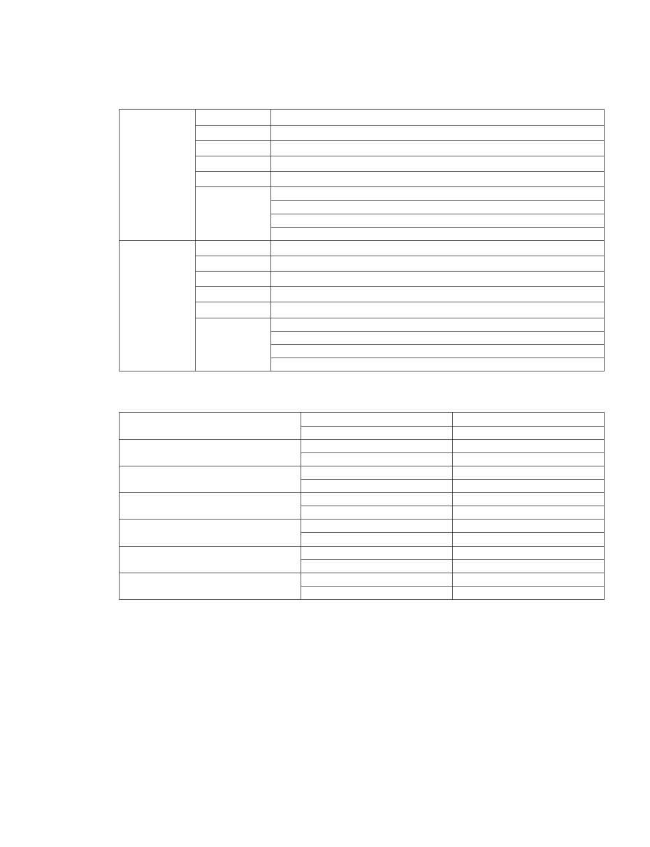
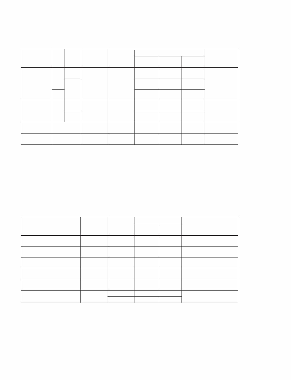
01V96 10 In these specifications, when dB represents a specific voltage, 0 dB is referenced to 0.775 Vrms. For 2TR IN levels, 0 dBV is referenced to 1.00 Vrms. All input AD converters (CH INPUT 1–16) are 24-bit linear, 128-times oversampling. (@fs=44.1, 48 kHz) +48 V DC (phantom power) is supplied to CH INPUT (1–12) XLR type connectors via individual switches. Three PHANTOM +48V switches CH1–4, 5–8, 9–12 turn on the phantom power for inputs 1–4, 5–8, 9–12 respectively. In these specifications, when dB represents a specific voltage, 0 dB is referenced to 0.775 Vrms. 2TR OUT [L, R] levels, 0 dBV is referenced to 1.00 Vrms. All output DA converters are 24-bit, 128-times oversampling. (@fs=44.1, 48 kHz) Input PAD GAIN Actual Load Impedance For Use With Nominal Input level Connector Sensitivity *1 *1. Sensitivity is the lowest level that will produce an output of +4 dB (1.23 V) or the nominal output level when the unit is set to maximum gain. (All faders and level controls are maximum position.) Nominal Max. before clip INPUT A/B 1–12 0 –60 dB 3k Ω 50–600 Ω Mics & 600 Ω Lines –70 dB (0.245 mV) –60 dB (0.775 mV) –40 dB (7.75 mV) A: XLR-3-31 type (Balanced) *2 B: Phone jack (TRS) (Balanced) *3 *2. XLR-3-31 type connectors are balanced (1=GND, 2=HOT, 3=COLD). *3. Phone jacks are balanced (Tip=HOT, Ring=COLD, Sleeve=GND). –16 dB –26 dB (38.8 mV) –16 dB (123 mV) +4 dB (1.23 V) 20 –6 dB (338 mV) +4 dB (1.23 V) +24 dB (12.28 V) INPUT 13–16 — –26 dB 10k Ω 600 Ω Lines –36 dB (1.23 mV) –26 dB (38.8 mV) –6 dB (388 mV) Phone jack (TRS) (Balanced) *3 +4 dB –6 dB (388 mV) +4 dB (1.23 V) +24 dB (12.28 V) CH INSERT IN 1–12 — 10k Ω 600 Ω Lines –12 dB (195 mV) –2 dB (616 mV) +18 dB (6.16 V) Phone jack (TRS) (Unbalanced) *4 *4. CH INSERT IN/OUT phone jacks are unbalanced. (Tip=OUTPUT, Ring=INPUT, Sleeve=GND). 2TR IN [L, R] — 10k Ω 600 Ω Lines –10 dB (316 mV) –10 dBV (316 mV) +10 dBV (3.16 V) RCA pin jack (Unbalanced) Output Actual Source Impedance For Use With Nominal Output level Connector Nominal Max. before clip STEREO OUT [L, R] 150 Ω 600 Ω Lines +4 dB (1.23 V) +24 dB (12.28 V) XLR-3-32 type (Balanced) *1 *1. XLR-3-32 type connectors are balanced (1=GND, 2=HOT, 3=COLD). OMNI OUT 1–4 150 Ω 10k Ω Lines +4 dB (1.23 V) +24 dB (12.28 V) Phone jack (TRS) (Balanced) *2 *2. Phone jacks are balanced (Tip=HOT, Ring=COLD, Sleeve=GND). MONITOR OUT [L, R] 150 Ω 10k Ω Lines +4 dB (1.23 V) +24 dB (12.28 V) Phone jack (TRS) (Balanced) *2 CH INSERT OUT 1–12 600 Ω 10k Ω Lines –2 dB (616 mV) +18 dB (6.16 V) Phone jack (TRS) (Unbal- anced) *3 *3. CH INSERT IN/OUT phone jacks are unbalanced. (Tip=OUTPUT, Ring=INPUT, Sleeve=GND). 2TR OUT [L, R] 600 Ω 10k Ω Lines –10 dBV (316 mV) +10 dBV (3.16 V) RCA Pin Jack (Unbalanced) PHONES 100 Ω 8 Ω Phones 4 mW 25 mW Stereo Phone Jack (TRS) (Unbalanced) *4 *4. PHONES stereo phone jack is unbalanced (Tip=LEFT, Ring=RIGHT, Sleeve=GND). 40 Ω Phones 12 mW 75 mW Analog Input Spec Analog Output Spec (アナログ入力仕様) (アナログ出力仕様)
This comprehensive service manual includes specifications, panel layout, circuit board layout, block diagram, disassembly procedure, LSI pin description, IC block diagram, circuit boards, inspection, MIDI implementation chart, overall circuit diagram, and parts list. It provides detailed instructions and images for repairing and servicing Yamaha products. The manual is an official high-resolution document, ensuring excellent print quality. Instant access is available after payment, with no shipping delays. The manual is in English and is compatible with various platforms such as Windows, MAC, and Linux.
Whether you are a professional mechanic or a DIY enthusiast, this manual is an invaluable resource for maintaining and repairing Yamaha products. For other Yamaha product service manuals, feel free to inquire!
Recently Viewed
5,521,897Happy Clients
2,594,462eManuals
1,120,453Trusted Sellers
15Years in Business
Price:
Actual Price:
Yamaha 01V96 01-V96 01V-96 complete service manual