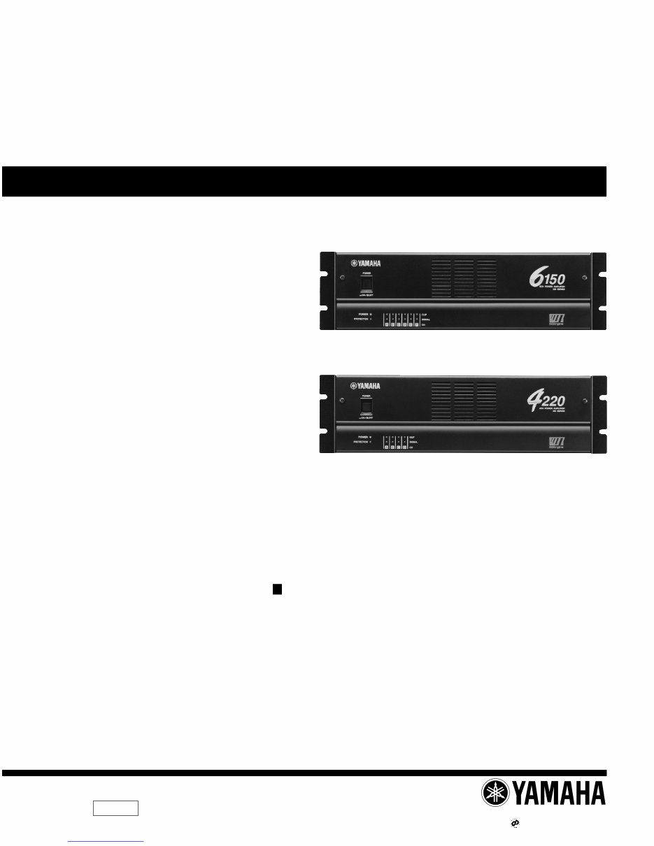
Yamaha XM6150 + XM4220 Service Manual & Repair Guide
What's Included?
Lifetime Access
Fast Download Speeds
Online & Offline Access
Access PDF Contents & Bookmarks
Full Search Facility
Print one or all pages of your manual
SERVICE MANUAL PA 011495 20000301-140000 1.5K-2501 Printed in Japan ’00.02 HAMAMATSU, JAPAN CONTENTS SPECIFICATIONS ................................................ 3/4 PANEL LAYOUT .................................... 5 CIRCUIT BOARD LAYOUT ................. 6 BLOCK DIAGRAM ............................ 8 DISASSEMBLY PROCEDURE .............................. 9 IC BLOCK DIAGRAM ................................. 13 DIMENSIONS ......................................................... 13 CIRCUIT BOARDS ...................................... 14 INSPECTIONS ....................................................... 24/25 PARTS LIST OVERALL CIRCUIT DIAGRAM XM6150 XM4220 XM6150/XM4220 POWER AMPLIFIER Downloaded from www.Manualslib.com manuals search engine
XM6150/XM4220 2 IMPOR TANT NOTICE FOR THE UNITED KINGDOM Connecting the Plug and Co Connecting the Plug and Co Connecting the Plug and Co Connecting the Plug and Co Connecting the Plug and Cord IMPORTANT. The wires in this main lead are coloured in accordance with the following code: BLUE: NEUTRAL BROWN: LIVE As the colours of the wires in the main lead of this apparatus may not correspond with the coloured markings identifying the terminals in your plug, proceed as follows: The BLUE wire must be connected to the terminal that is marked with the letter N (or coloured BLACK). The BROWN wire must be connected to the terminal that is marked with the letter L (or coloured RED). Be certain that neither core is connected to the earth terminal of the three pin plug. IMPOR TANT NOTICE This manual has been provided for the use of authorized Yamaha Retailers and their service personnel. It has been assumed that basic service procedures inherent to the industry, and more specifically Yamaha Products, are already known and under- stood by the users, and have therefore not been restated. WARNING : Failure to follow appropriate service and safety procedures when servicing this product may result in per- sonal injury, destruction of expensive components and failure of the product to perform as specified. For these reasons, we advise all Yamaha product owners that all service required should be performed by an authorized Yamaha Retailer or the appointed service representative. IMPORTANT : This presentation or sale of this manual to any individual or firm does not constitute authorization certifi- cation, recognition of any applicable technical capabilities, or establish a principal-agent relationship of any form. The data provided is belived to be accurate and applicable to the unit(s) indicated on the cover. The research engineering, and service departments of Yamaha are continually striving to improve Yamaha products. Modifications are, therefore, inevitable and changes in specification are subject to change without notice or obligation to retrofit. Should any discrepancy appear to exist, please contact the distributor’s Service Division. WARNING : Static discharges can destroy expensive components. Discharge any static electricity your body may have accumulated by grounding yourself to the ground bus in the unit (heavy gauge black wires connect to this bus.) IMPORTANT : Turn the unit OFF during disassembly and parts replacement. Recheck all work before you apply power to the unit. WARNING: CHEMICAL CONTENT NOTICE! The solder used in the production of this product contains LEAD. In addition, other electrical/electronic and/or plastic (Where applicable) components may also contain traces of chemicals found by the California Health and Welfare Agency (and possibly other entities) to cause cancer and/or birth defects or other reproductive harm. DO NOT PLACE SOLDER, ELECTRICAL/ELECTRONIC OR PLASTIC COMPONENTS IN YOUR MOUTH FOR ANY REASON WHAT SO EVER! Avoid prolonged, unprotected contact between solder and your skin! When soldering, do not inhale solder fumes or expose eyes to solder/flux vapor! If you come in contact with solder or components located inside the enclosure of this product, wash your hands before handling food. WARNING Components having special characteristics are marked and must be replaced with parts having specification equal to those originally installed. Downloaded from www.Manualslib.com manuals search engine
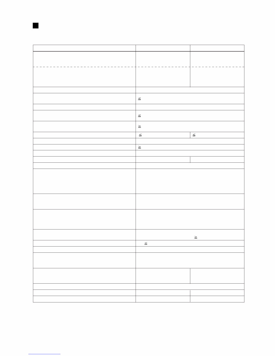
XM6150/XM4220 3 SPECIFICATIONS XM6150 XM4220 Power Output Level (Rated Power) 8Ω 100 W x 6 140 W x 4 20 Hz~20 kHz 4Ω 120 W x 6 180 W x 4 THD+N= 0.2% 8Ω/BRIDGE 240 W x 3 360 W x 2 1 kHz 8Ω 120 W x 6 170 W x 4 THD+N= 0.2% 4Ω 150 W x 6 220 W x 4 8Ω/BRIDGE 300 W x 3 440 W x 2 70.7V/BRIDGE 150 W x 3 350 W x 2 Power Bandwidth Half Power 10 Hz~40 kHz (THD+N= 1%) Total Harmonic Distortion (THD + N) 20 Hz~20 kHz, Half Power 0.2% Frequency Response 8Ω, Po= 1 W 0 dB, 0.5 dB, –1 dB 20 Hz~50 kHz Intermodulation distortion (IMD) 60 Hz:7 kHz, 4:1, Half Power 0.2% Channel Separation Half Power, RL= 8Ω, 1 kHz 60 dB Vol. 0(maximum), input 600Ω shunt Residual Noise Vol. 0(maximum) –68 dB –66.5 dB SN Ratio 12.7 kHz LPF 100 dB Damping Factor 8Ω, 1f= 1 kHz 100 Sensitivity (Vol. 0:maximum) Rated Power into 8 Ω 0 dB Voltage Gain (Vol. 0:maximum) Input Impedance 30 kΩ/Balanced, 15 kΩ/Unbalanced Controls Front Panel POWER switch (ON/OFF) Rear Panel Volume (31 position) /ch BRIDGE switch (ON/OFF) /2ch HPFswitch (ON/OFF) /ch fc=80 Hz, –12 dB/oct. CH A TO ALL CH switch Connectors Input XLR-3-31 type/ch Euroblock connector Output 5-way binding posts Indicators POWER Green PROTECTION Red CLIP Red SIGNAL Green Protection Circuits POWER switch ON muting, DC detection, Temp. detection (heatsink temp 85°C) PC limiter RL 2 Ω Fan Speed Low/~50°C, Variable, High/70°C~ Power Requirements US & Canada 120 V, 60 Hz Europe 230 V, 50 Hz Other 240 V, 50 Hz Power Consumption Idling 45 W 45 W 1/8 output power, 4Ω 400 W/550 VA 400 W/500 VA Maximum output, 4Ω 1800 W 1800 W Dimensions (W x H x D) 480 x 132 x 319 mm Weight 18 kg 18 kg Accesaries Euroblock connector x 6 Euroblock connector x 4 0 dB=0.775 Vrms, Half Power=1/2 Power Output Level (Rated Power) For European Model Purchaser/User information specified in EN55103-1 and EN55103-2. Inrush Current: 56A Conformed Enviroment: E1, E2, E3 and E4. 12.7 kHz LPF 32.1 dB 33.6 dB Downloaded from www.Manualslib.com manuals search engine
XM6150/XM4220 4 Downloaded from www.Manualslib.com manuals search engine
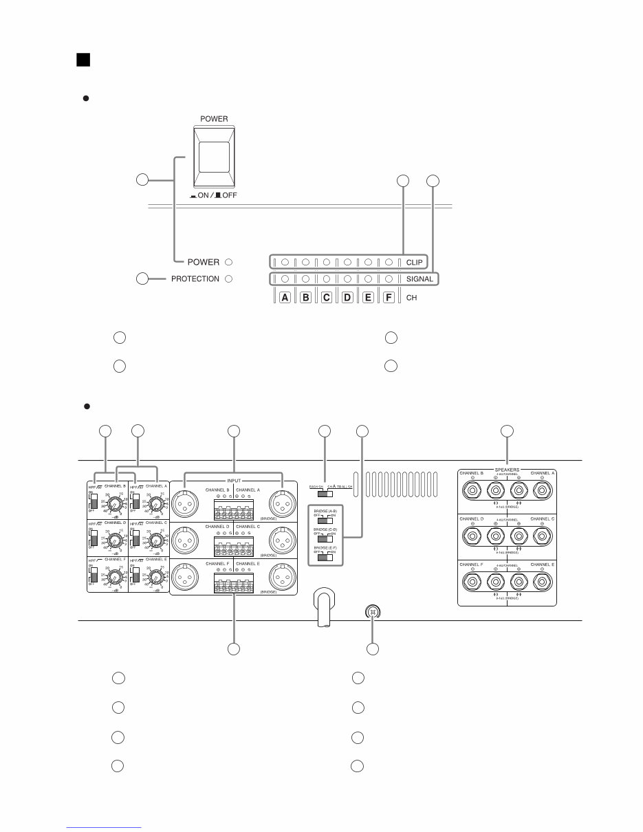
XM6150/XM4220 5 PANEL LAYOUT Front Panel 1 POWER switch and indicator 2 PROTECTION indicator 3 CLIP indicator 4 SIGNAL indicator 1 2 3 4 * The illustration shows model XM6150. Rear Panel HPF switches Attenuators XLR inputs 80 Euroblock connectors CH A TO ALL CH switch BRIDGE switches 1 2 3 4 5 6 7 8 * The illustration shows model XM6150. 1 2 3 4 7 5 6 8 GND terminals Speaker outputs Downloaded from www.Manualslib.com manuals search engine
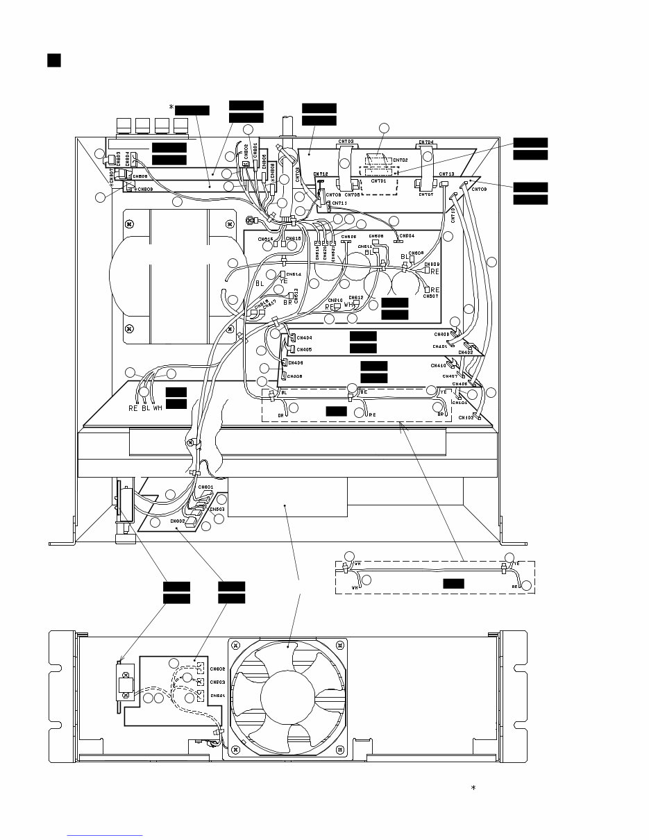
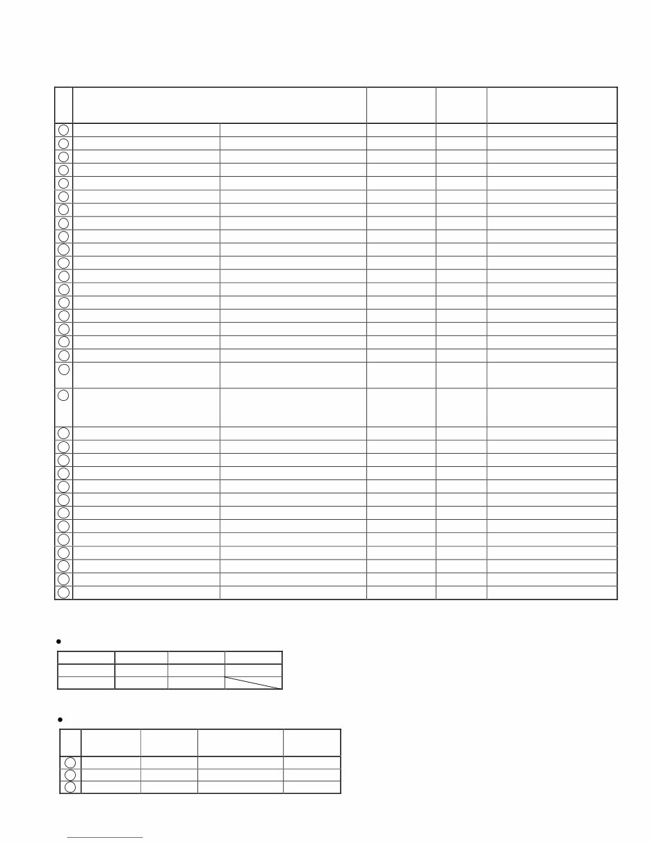
XM6150/XM4220 7 DESTINATION PIN/ CONNECTOR ASSEMBLY LENGHT PART LIST REF NO. 1 DRV6 or DRV4 (4/5)-CN601 REAR6 or REAR4 (4/6)-CN804 SIG 9P Overall Assembly [330] 2 DRV6 or DRV4 (4/5)-CN603 Fan Fan 2P Overall Assembly [160] 3 DRV6 or DRV4 (4/5)-CN602 DRV6 or DRV4 (1/5)-CN404 CLP 8P Overall Assembly [320] 4 DRV6 or DRV4 (5/5)-W601 DRV6 or DRV4 (3/5)-CN614 AC1 1P 5 DRV6 or DRV4 (5/5)-W602 DRV6 or DRV4 (3/5)-CN613 AC2 1P 6 PA6 or PA4-W105 DRV6 or DRV4 (3/5)-CN610 +B 1P PA6 or PA4 C.B. [W105] 7 PA6 or PA4-W106 DRV6 or DRV4 (3/5)-CN611 GND 1P PA6 or PA4 C.B. [W106] 8 PA6 or PA4-W107 DRV6 or DRV4 (3/5)-CN612 -B 1P PA6 or PA4 C.B. [W107] 9 PA6 or PA4-W101 REAR6 or REAR4 (4/6)-CN801 OUT AB 2P PA6 or PA4 C.B. [W101] 10 PA6 or PA4-W102 REAR6 or REAR4 (5/6)-CN806 OUT CD 2P PA6 or PA4 C.B. [W102] 11 PA6-W103 REAR6 (6/6)-CN808 OUT EF 2P PA6 C.B. [W103] 12 PA6 or PA4-CN101 DRV6 or DRV4 (2/5)-CN410 FFC 10P/L60 Overall Assembly [240] 13 PA6 or PA4-CN102 DRV6 or DRV4 (1/5)-CN402 FFC 14P/L80 Overall Assembly [230] 14 DRV6 or DRV4 (1/5)-CN405 DRV6 or DRV4 (2/5)-CN408 FFC 6P/L50 Overall Assembly [260] 15 DRV6 or DRV4 (2/5)-CN409 DRV6 or DRV4 (3/5)-CN606 5P/L180 Overall Assembly [290] 16 DRV6 or DRV4 (1/5)-CN403 DRV6 or DRV4 (2/5)-CN407 FFC 8P/L60 Overall Assembly [270] 17 DRV6 or DRV4 (1/5)-CN401 REAR6 or REAR4 (3/6)-CN710 FFC 14P/L150 Overall Assembly [310] 18 DRV6 or DRV4 (2/5)-CN406 REAR6 or REAR4 (3/6)-CN709 FFC 6P/L140 Overall Assembly [280] 19 Power Transformer DRV6 or DRV4 (3/5) -CN617, CN618 Power Transformer 1P Overall Assembly [70] 20 Power Transformer DRV6 or DRV4 (3/5)-CN605, CN607, CN608, CN609 REAR6 or REAR4 (3/6)-CN713 Power Transformer 1P Overall Assembly [70] 21 DRV6 or DRV4 (3/5)-CN616 AC Cord AC Cord 1P Overall Assembly [40] 22 DRV6 or DRV4 (3/5)-CN615 AC Cord AC Cord 1P Overall Assembly [40] 23 DRV6 or DRV4 (3/5)-CN619 REAR6 or REAR4 (4/6)-W801 OUT G 2P 24 DRV6 or DRV4 (3/5)-CN620 REAR6 or REAR4 (5/6)-W802 OUT G 2P 25 DRV6(3/5)-CN621 REAR6(6/6)-W803 OUT G 2P REAR6 C.B. [W803] 26 REAR6 or REAR4 (4/6)-CN803 REAR6 or REAR4 (5/6)-CN805 FFC 6P/L70 Rear Assembly [R150] 27 REAR6 (5/6)-CN807 REAR6 (6/6)-CN809 FFC 6P/L70 Rear Assembly [R150] 28 REAR6 or REAR4 (3/6)-CN712 REAR6 or REAR4 (4/6)-CN802 3P/L80 Rear Assembly [R130] 29 REAR6 or REAR4 (2/6)-CN706 REAR6 or REAR4 (3/6)-CN708 FFC 20P/L50 Rear Assembly [R60] 30 DRV6 or DRV4 (3/5)-CN604 REAR6 or REAR4 (3/6)-CN711 7P/L180 Rear Assembly [R140] 31 REAR6 or REAR4 (2/6)-CN703 REAR6 or REAR4 (3/6)-CN705 FFC 20P/L50 Rear Assembly [R60] 32 REAR6 or REAR4 (2/6)-CN704 REAR6 or REAR4 (3/6)-CN707 FFC 35P/L50 Rear Assembly [R70] 33 REAR6 or REAR4 (1/6)-CN701 REAR6 or REAR4 (2/6)-CN702 FFC 24P/L50 Rear Assembly [R50] CN801 CN806 CN808 XM6150 BR, RE OR, YE BE, BL XM4220 RE, WH YE, WH Japanese U.S. Canadian North European British Australian 19 YE BR BE RE 21 WH WH BE BE 22 BL BL BR BR DRV6 or DRV4 C.B. [W601] DRV6 or DRV4 C.B. [W602] DRV6 or DRV4 C.B. [W801] DRV6 or DRV4 C.B. [W802] Wire color Wire color Downloaded from www.Manualslib.com manuals search engine
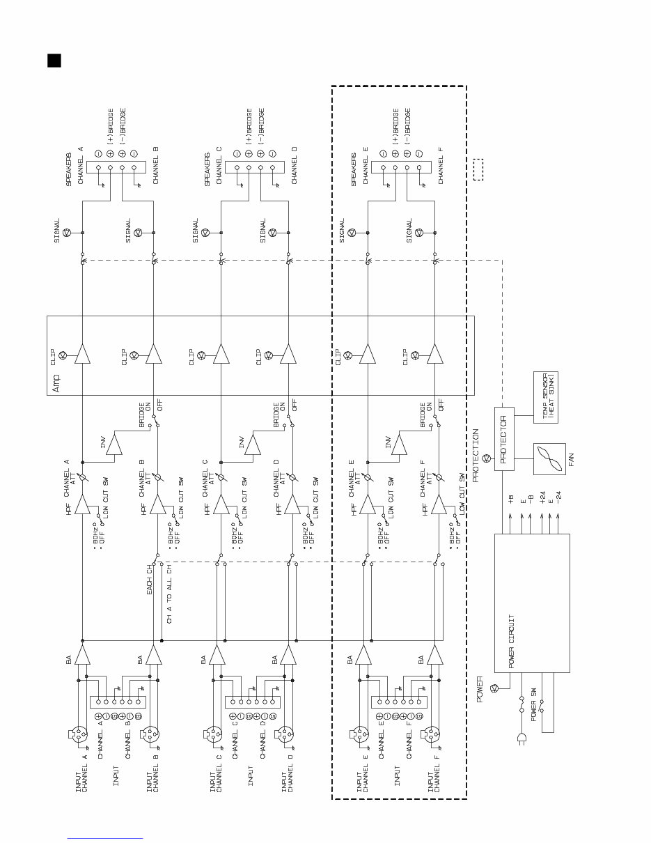
XM6150/XM4220 8 BLOCK DIAGRAM 5 7 6 1 2 3 1 2 3 1 2 3 1 2 3 1 2 3 1 2 3 IC701 5, 6 7 IC708 3 1 2 IC701 OP AMP OP AMP OP AMP 5, 6 7 IC707 2, 3 1 IC708 OP AMP OP AMP 2, 3 1 IC707 OP AMP 2, 3 1 IC709 OP AMP 5, 6 7 IC709 OP AMP 2, 3 1 IC710 OP AMP 2, 3 1 IC711 OP AMP 5, 6 7 IC710 OP AMP 5 7 6 IC702 OP AMP 3 1 2 IC702 OP AMP 5 7 6 IC703 OP AMP 3 1 2 IC703 OP AMP : XM6150 only KEC-92471 Downloaded from www.Manualslib.com manuals search engine
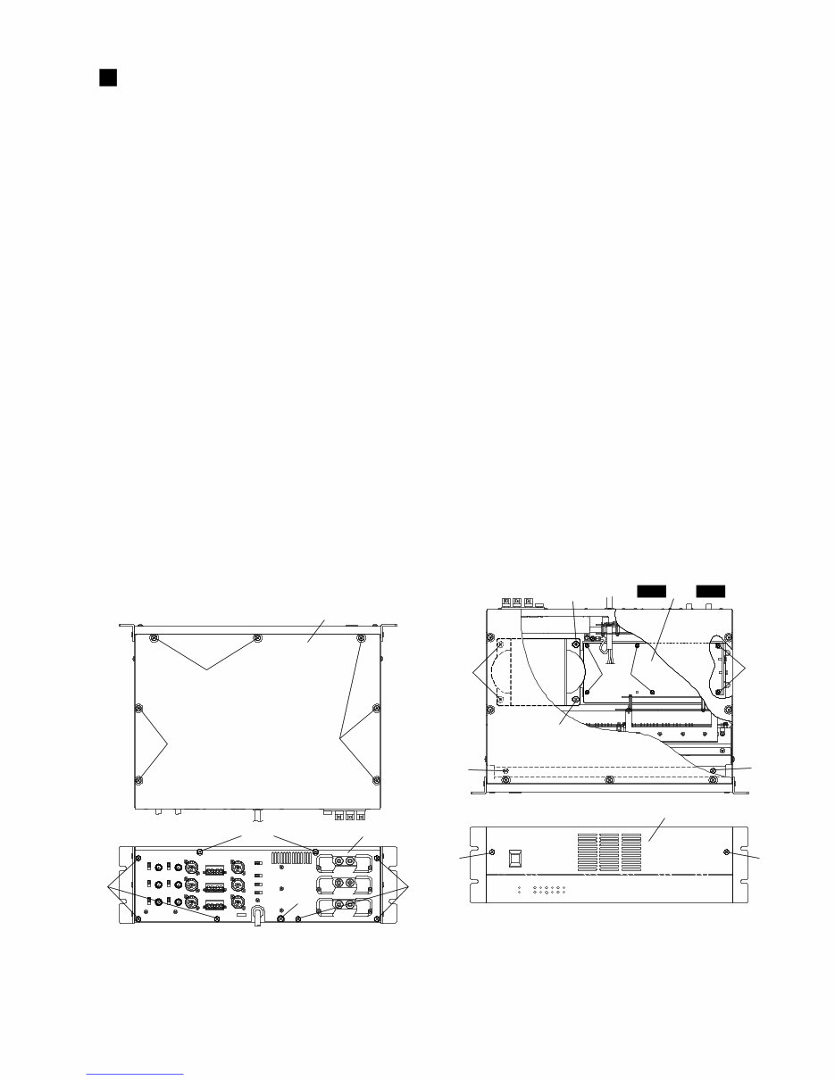
XM6150/XM4220 9 [480] [480] [480] [480] Rear assembly Top cover [400] [400] [490] DISASSEMBLY PROCEDURE 1. Top Cover 1-1 Remove the nine (9) screws marked [480]. The top cover can then be removed. (Fig.1) 2. Front Panel 2-1 Remove the top cover. (See procedure 1.) 2-2 Remove the four (4) screws marked [450]. The front panel can then be removed. (Fig.2) 3. Rear Assembly 3-1 Remove the top cover. (See procedure 1.) 3-2 Remove the six (6) screws marked [400] and the screw marked [490]. The rear assembly can then be removed. (Fig.1) 4. DRV6(3/5) Circuit Board <XM6150> DRV4(3/5) Circuit Board <XM4220> 4-1 Remove the top cover. (See procedure 1.) 4-2 Remove the rear assembly. (See procedure 3.) 4-3 Remove the four (4) screws marked [100], the two (2) screws marked [110] and the screw marked [60]. The DRV6(3/5) circuit board or the DRV4(3/5) circuit board can then be removed. (Fig.2) 5. Power Transformer 5-1 Remove the top cover. (See procedure 1.) 5-2 Remove the four (4) screws marked [80]. The power transformer can then be removed. (Fig.2) (Fig.1) [400]: Bonding Tapping Screw-B 4.0 X 8 MFZN2BL (VR779900) [480]: Bind Head Tapping Screw-B 4.0 X 8 MFZN2BL (EG340190) [490]: Bind Head Screw A4.0 X 8 MFZN2BL (VP156800) 〈 Top View 〉 〈 Rear View 〉 [60]: Bind Head Screw A4.0 X 8 MFZN2BL (VP156800) [80]: Bind Head Screw SP5.0 X 10 MFZN2BL (VU688100) [100]: Bind Head Tapping Screw-B 3.0 X 8 MFZN2BL (EP600190) [110]: Bind Head Tapping Screw-B 3.0 X 12 MFZN2BL (VQ074600) [450]: Bind Head Tapping Screw-B 4.0 X MFZN2BL (EG340190) [450] [450] [450] [450] DRV6 DRV4 3/5 or 3/5 Front panel Power Power Transformer Transformer Power Transformer [80] [110] [80] [80] [100] (Fig.2) 〈 Top View 〉 〈 Front View 〉 Downloaded from www.Manualslib.com manuals search engine
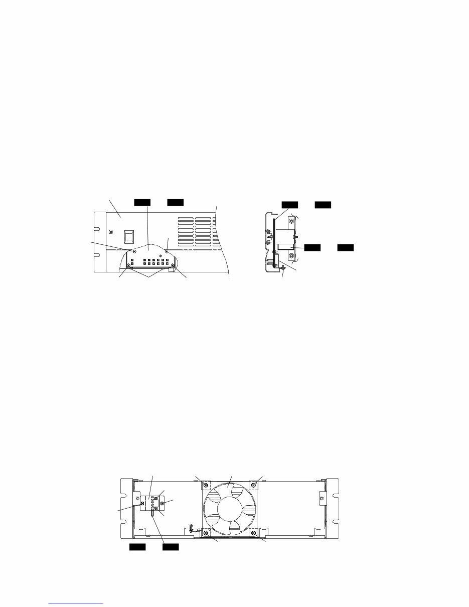
XM6150/XM4220 10 6. DRV6(4/5) Circuit Board <XM6150> DRV4(4/5) Circuit Board <XM4220> 6-1 Remove the top cover. (See procedure 1.) 6-2 Remove the front panel. (See procedure 2.) 6-3 Remove the two (2) screws marked [370A]. The DRV6(4/5) circuit board or the DRV4(4/5) circuit board can then be removed with the LED angle bracket. (Fig.3) 6-4 Remove the four (4) screws marked [370B]. The LED angle bracket can then be removed from the DRV6 (4/5) circuit board or the DRV4(4/5) circuit board. (Fig.3) 7. DRV6(5/5) Circuit Board <XM6150> DRV4(5/5) Circuit Board <XM4220> 7-1 Remove the top cover. (See procedure 1.) 7-2 Remove the front panel. (See procedure 2.) 7-3 Remove the two (2) screws marked [220]. The PSW angle bracket can then be removed. (Fig.4) 7-4 Pull out the PSW knob and remove the two (2) screws marked [210]. The DRV6(5/5) circuit board or the DRV4(5/5) circuit board can then be removed from the PSW angle bracket. (Fig.4) 8. Fan 8-1 Remove the top cover. (See procedure 1.) 8-2 Remove the front panel. (See procedure 2.) 8-3 Remove the four (4) screws marked [170]. The fan can then be removed. (Fig.4) [370A] [370B] [370A] [370B] [370B] [370B] DRV6 DRV4 4/5 or 4/5 DRV6 DRV4 4/5 or 4/5 DRV6 DRV4 5/5 or 5/5 Front panel LED angle bracket 〈 Right Side View 〉 (Fig.3) [370]: Bind Head Tapping Screw-B 3.0 X 8 MFZN2BL (EP600190) [170] [170] [170] [170] [210] [210] [220] [220] DRV6 DRV4 5/5 or 5/5 PSW angle bracket Fan (Fig.4) 〈 Front View 〉 [170]: Bind Head Screw 4.0 X 45 MFZN2BL (VB857700) [210]: Bind Head Screw 3.0 X 8 MFZN2BL (VB659000) [220]: Bind Head Tapping Screw-B 3.0 X 8 MFZN2BL (EP600190) Downloaded from www.Manualslib.com manuals search engine
Are you experiencing issues with your Yamaha Power Amplifier? Why spend a lot on repairs or replacements when you can handle it yourself? This comprehensive service and repair manual is utilized by Official Certified Yamaha Technicians and is designed to assist you in troubleshooting and repairing your amplifier.
Specifications
Panel Layout
Circuit Board Layout
Block Diagram
Disassembly Procedure
IC Block Diagram
Dimensions
Circuit Boards
Inspections
Parts List
Overall Circuit Diagram
This service manual contains detailed instructions, accompanied by images, to guide you through the repair and servicing process effectively. It is produced in high resolution, ensuring excellent print quality for the pages you require.
Upon payment, you will gain instant access to the manual, eliminating shipping delays and fees. The manual is available in English and is compatible with both Windows and MAC platforms.
If you are unable to locate a specific service manual, feel free to reach out to us with your request. With one of the most extensive service manual databases, we are well-equipped to assist you.
Recently Viewed
5,521,897Happy Clients
2,594,462eManuals
1,120,453Trusted Sellers
15Years in Business
Price:
Actual Price:
Yamaha XM6150 + XM4220 Service Manual & Repair Guide