RCA TRANSMITTING ELECTRON VACUUM TUBE Catalog Radio Book
What's Included?
Lifetime Access
Fast Download Speeds
Online & Offline Access
Access PDF Contents & Bookmarks
Full Search Facility
Print one or all pages of your manual
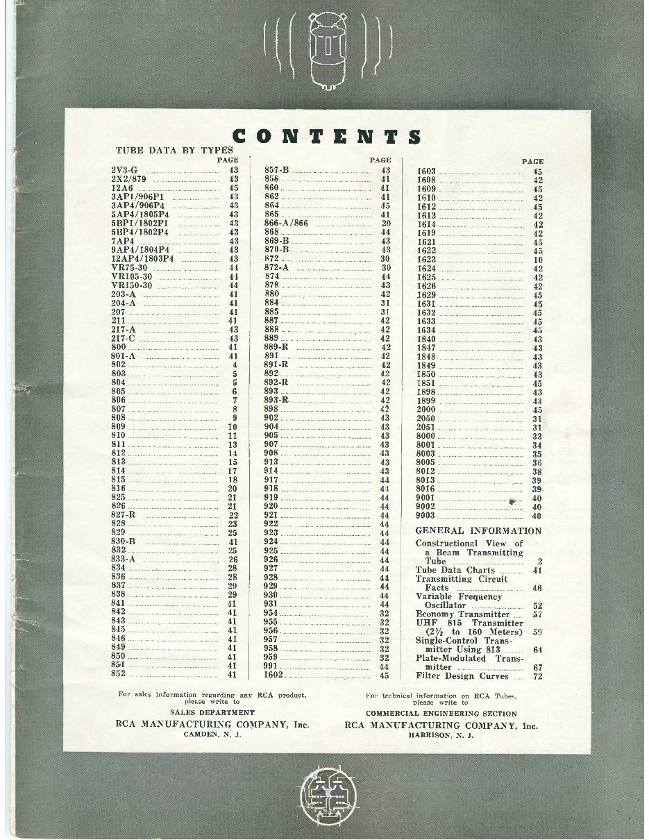
° IBUg oE for TRANSMITTING TUBES (3L ENGINEERS EXPERIMENTERS Hcc4, SPECIAL CHART FOR TRANSMITTING TUBES (Air - and Water-Cooled), CATHODE -RAY TUBES, SPECIAL-PURPOSE TUBES AND PHOTOTUBES P ents I CAM DEN, N, U. S.
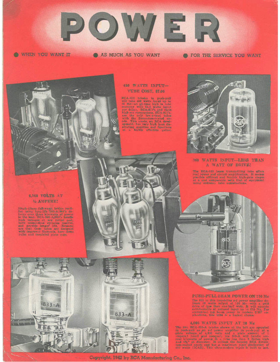
WHEN YOU WANT IT AS MUCH AS YOU WANT FOR THE SERVICE YOU WANT 450 WA'I'TS INPUT TUBE COST, $7.00 RCA -812 triodes in push -pu will take 450 watts input up to 60 Mc -an all -time high in tub economy with 64.3 watts input per dollar. RCA -812's and their high-mu companions, RCA- 811's, e the only low- priced tubes "th the Zirconium -coated an- de. This anode, an RCA devel ment, has very high heat di pating qualities and function a highly effective Bette 360 WATTS INPUT -LESS THAN A WATT OF DRIVE! The RCA -813 beam transmitting tube offers real power and circuit' amplification. It makes possible efficient and flexible high -gain stages at a cost comparable with that of equipment using ordinary tube combinations. 6,360 VOLTS AT 1/2 AMPERE!: Single -phase full -wave, bridge recti fier using long -life 866- A/866's de livers over three kilowatts of powe to the load. RCA -866- A /866's handl high voltages at low initial cost, have tremendous emission reserve, and provide longer life. Reasons are that these tubes are design with improved filaments, have dom bulbs and insulated plate caps. -10Slierrrewi P Copyright, 1942 by RCA Manufacturing Co., Inc. USH -PULL BEAM POWER e 815 in this tuned -line r -f powe vers 50 watts output at 150 Mc drive of less than one -half watt. It satisfactorily at reduced input up to economical p -p beam power in mod plications, this tube is a logical ch 4,000 WATTS INPUT AT 20 e two RCA -833 -A triodes shown at the left are Oper in push -pull as an r -f power amplifier in push -pull ;: plate voltage of 4,000 volts and a plate current o ¢ ' ampere! Small and compact, the 833 -A will handle eral kilowatts of power in a tube less than 9 inches hiE... and 4 %" in diameter. It utilizes the famous RCA Zircon- ium- coated anode and has a maximum plate dissipation of 450 watts (ICAS). This ultra -modern triode is built to last.
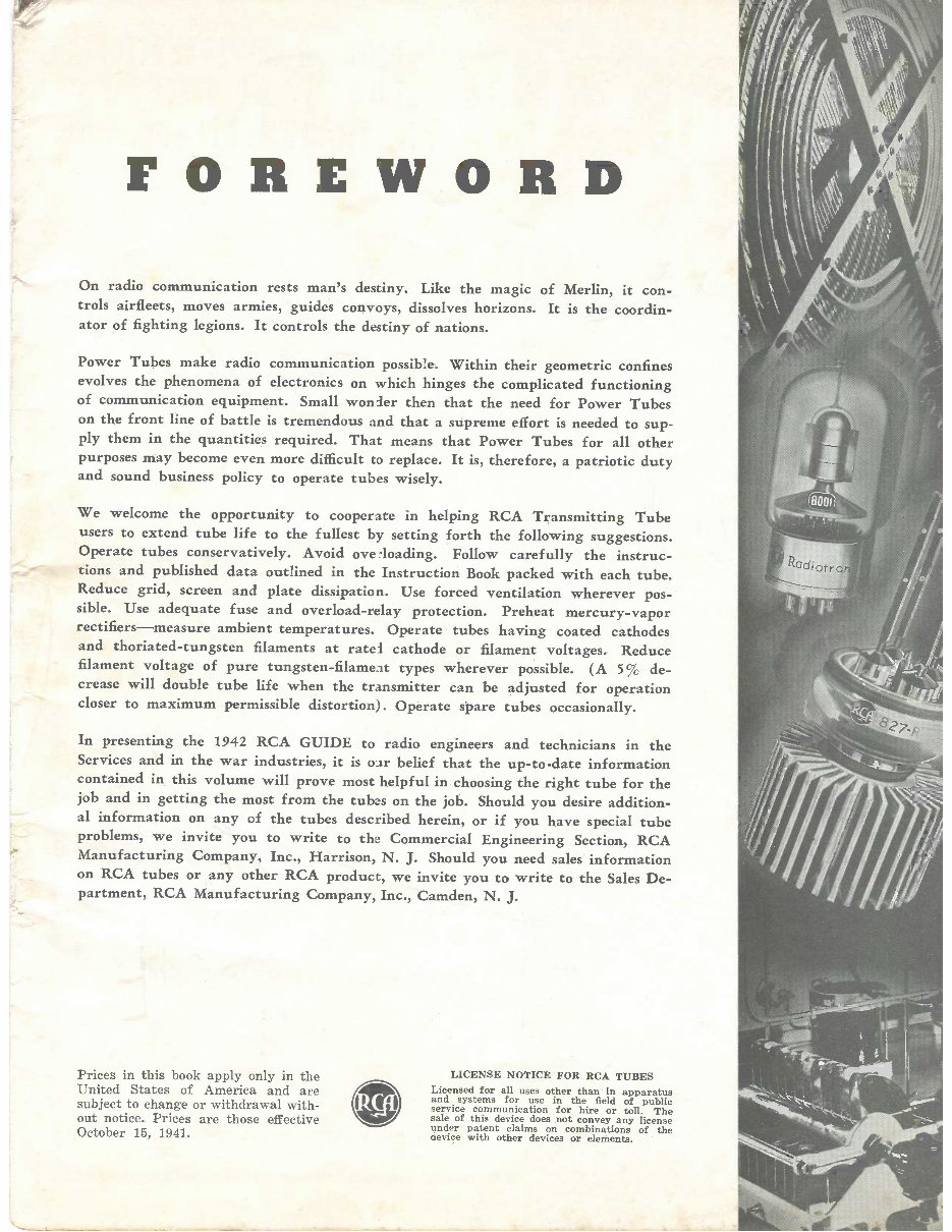
FOREWORD On radio communication rests man's destiny. Like the magic of Merlin, it con- trols airfleets, moves armies, guides convoys, dissolves horizons. It is the coordin- ator of fighting legions. It controls the destiny of nations. Power Tubes make radio communication possible. Within their geometric confines evolves the phenomena of electronics on which hinges the complicated functioning of communication equipment. Small wonier then that the need for Power Tubes on the front line of battle is tremendous and that a supreme effort is needed to sup- ply them in the quantities required. That means that Power Tubes for all other purposes may become even more difficult to replace. It is, therefore, a patriotic duty and sound business policy to operate tubes wisely. We welcome the opportunity to cooperate in helping RCA Transmitting Tube users to extend tube life to the fullest by setting forth the following suggestions. Operate tubes conservatively. Avoid ove °loading. Follow carefully the instruc- tions and published data outlined in the Instruction Book packed with each tube. Reduce grid, screen and plate dissipation. Use forced ventilation wherever pos- sible. Use overload -relay protection. mercury rectifiers -measure ambient temperatures. Operate tubes having coated cathodes and thoriated- tungsten filaments at ratei cathode or filament voltages. Reduce filament voltage of pure tungsten -filament types wherever possible. (A 5% de- crease will double tube life when the transmitter can be adjusted for operation closer to maximum permissible distortion) . Operate spare tubes occasionally. In presenting the 1942 RCA GUIDE to radio engineers and technicians in the Services and in the war industries, it is oar belief that the up -to -date information contained in this volume will prove most helpful in choosing the right tube for the job and in getting the most from the tubes on the job. Should you desire addition- al information on any of the tubes described herein, or if you have special tube problems, we invite you to write to the Commercial Engineering Section, RCA Manufacturing Company, Inc., Harrison, N. J. Should you need sales information on RCA tubes or any other RCA product, we invite you to write to the Sales De- partment, RCA Manufacturing Company, Inc., Camden, N. J. Prices in this book apply only in the United States of America and are subject to change or withdrawal with- out notice. Prices are those effective October 15, 1941. LICENSE NOTICE FOR RCA TUBES Licensed for all uses other than in apparatus and systems for use in the field of public service communication for hire or toll. The sale of this device does not convey any license under patent claims on combinations of the device with other devices or elements.
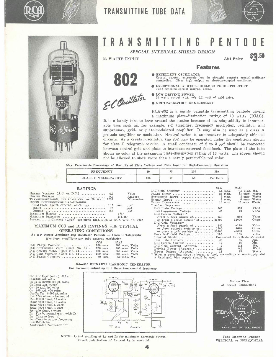
TRANSMITTING TUBE DATA TRANSMITTING PENTODE SPECIAL INTERNAL SHIELD DESIGN 33 WATTS INPUT 802 Max. It is able List Price Features $3.50 EXCELLENT OSCILLATOR Crystal current extremely low in straight pentode crystal- oscillator connection. Gives high output as electron -coupled oscillator. EXCEPTIONALLY WELL -SHIELDED TUBE STRUCTURE Tube contains special internal shield. O LOW DRIVING POWER 23 watts output with only 0.3 watt of grid drive. NEUTRALIZATION UNNECESSARY RCA -802 is a highly versatile transmitting pentode having a maximum plate- dissipation rating of 13 watts (ICAS). a handy tube to have around the station because of its adaptability to innumer- uses such as, for example, r -f amplifier, frequency multiplier, oscillator, and suppressor -, grid- or plate -modulated amplifier. It may also be used as a class A pentode amplifier or modulator. Neutralization is unnecessary in adequately shielded circuits. As a crystal oscillator, the 802 may be operated under the conditions shown for class C telegraph service. A small condenser of 2 to 3 μμf should be connected between control grid and plate to introduce external feed -back. The plate of the tube shows no color at the maximum plate- dissipation rating of 13 watts. The screen should not be allowed to show more than a barely perceptible red color. Permissible Percentage of Max. Rated Plate Voltage and Plate Input for High -Frequency Operation FREQUENCY 30 55 100 Mc CLASS C TELEGRAPHY 100 77 55 Per Cent RATINGS HEATER VOLTAGE (A.C. OR D.C) 6.3 HEATER CURRENT 0.9 TRANSCONDUCTANCE, FOR PLATE CUR. OF 20 MA 2250 DIRECT INTERELECTRODE CAPACITANCES: Grid -Plate (With external shielding) 0.15 max. μμf Input 12 μμ.f Output 8.5 μμf MAXIMUM HEIGHT 5%" MAXIMUM DIAMETER 2-1/16" SOCKET 7- Contact (0.855" pin -circle dia), such as RCA type No. 9923 Volts Ampere Micromhos MAXIMUM CCS and ICAS RATINGS with TYPICAL OPERATING CONDITIONS As R -F Power Amplifier and Oscillator Penfode - Class C Telegraphy Key -down conditions per tube without modulation CCS ICAS 500 max. 600 max. Volts 200 max. 200 max. Volts 260 max. 250 max. Volts -200 max. -200 max. Volts 60 max. 60 max. Ma. D -C PLATE VOLTAGE D -C SUPPRESSOR VOLT. (GRID No. 3) D -C SCREEN VOLT. (GRID No. 2) D -C GRID VOLTAGE (GRID No. 1) D -C PLATE CURRENT CCS WAS D -C GRID CURRENT 7.5 max. 7.5 max. Ma. PLATE INPUT 25 max. 33 max. Watts SUPPRESSOR INPUT 2 max. 2 max. Watts SCREEN INPUT 6 max. 6 max. Watts PLATE DISSIPATION 10 max. 13 max. Watts TYPICAL OPERATION : D -C Plate Voltage 500 606 Volts D -C Suppressor Voltage 40 40 Volta D -C Screen Voltage:* From a fixed supply of 250 250 Volts or from a series resistor of 20800 22000 Ohms D -C Grid Voltage:* From a fixed supply of -100 -120 Volts or from cathode resistor of 1700 1620 Ohms or from a grid resistor of 50000 42000 Ohms Peak R -F Grid Voltage 155 165 Volta Internal Shield Connected to cathode at socket D -C Plate Current 45 55 Ma. D -C Screen Current 12 16 Ma. D -C Grid Current (Approx.) 2 2.4 Ma. Driving Power (Approx.) 0.25 0.3 Watt Power Output (Approx.) 16 23 Watts * When a preceding stage is keyed, a fixed, low -voltage screen supply and a fixed grid bias supply should be used. 802 -807 REINARTZ HARMONIC GENERATOR For harmonic output up to 8 times fundamental frequency Ci =2 to 3μμf (max.), 600 v. C2 =100 μμf, mica Cs C4 Ca Cio= 0.005 μß, mica Cs Ce =1 μμf /meter C7=50 paf, 600 volts Cs =100 aaf, 600 volts Cu C12 C18 =0.005 μf, mica Ri =5000 ohms, wire wound Rs =20000 ohms, 10 watts R8=15000 ohms, 10 watts Ra =15000 ohms, 5 watts Rs =10000 ohms, watt Ra =200 ohms, 5 watts Li =For 1/ crystal freq., with Co L2 =Tune to freq. "f" Ls =Tune to output frequency La =R -f choke X= Crystal, frequency "f" RCA -802 Fo r Cy OUTPUT (2f TO 8f) NOTE: Adjust coupling of 112 and L3 for maximum harmonic output. Correct polarization of L2 and Ls is essential. 4 Bottom View of Socket Connections Tube Mounting Position VERTICAL or HORIZONTAL
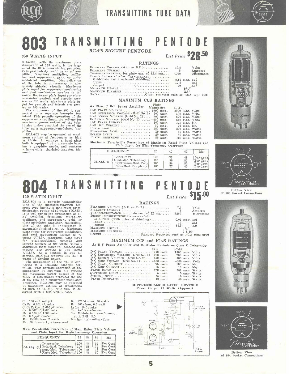
TRANSMITTING TUBE DATA 803 TRANSMITTING PENTODE RCA'S BIGGEST PENTODE 350 WATTS INPUT RCA -803, with its maximum plate dissipation of 125 watts, is the larg- est of the RCA transmitting pentodes. It is particularly useful as an r -f am- plifier, frequency multiplier, oscilla- tor, and suppressor -, grid -, or plate - modulated amplifier. Neutralization of the tube is unnecessary in ade- quately shielded circuits. Maximum plate input for suppressor modulation and grid modulation services is 180 watts. Maximum plate input for plate - modulated pentode and tetrode serv- ices is 250 watts. Maximum plate in- put for pentode and tetrode c -w serv- ice is 350 watts. The suppressor of the 803 is con- nected to a separate base -pin ter- minal. This permits operation of the suppressor at optimum d -c voltage for maximum power output of the tube. It also makes practical the use of the tube as a suppressor -modulated am- plifier. RCA -803 may be operated at maxi- mum ratings at frequencies as high as 20 -Mc. It employs a hard glass bulb, is equipped with a ceramic base, has a graphite anode, and contains a heavy-duty, thoriated- tungsten fila- ment. RATINGS List Price $28.50 FILAMENT VOLTAGE (A.C. Or D.0 ) 10.0 Volts FILAMENT CURRENT 5 Amperes TRANSCONDUCTANCE, for plate cur. of 62.5 ma 4000 Micromhos DIRECT 1NTERELECTRODE CAPACITANCES: Grid -Plate (with external shielding) 0.15 max. μμf Input 17.5 μμf Output 29 μμf MAXIMUM HEIGHT 9s%" MAXIMUM DIAMETER 2h" SOCKET Giant 5- contact such as RCA type 9927 MAXIMUM CCS RATINGS I'late As Class C R -F Power Amplifier Modulation C.W. D -C PLATE VOLTAGE 1600 max. 2000 max. Volts D -C SUPPRESSOR VOLTAGE (Grid No. 3) 500 max. 500 max. Volts D -C SCREEN VOLTAGE (Grid No. 2) 500 max. 600 max. Volts D -C GRID VOLTAGE (Grid No. 1) -500 max. -500 max. Volts D -C PLATE CURRENT 160 max. 175 max. Ma. D -C GRID CURRENT 50 max. 50 max. Ma. PLATE INPUT 250 max. 350 max. Watts SUPPRESSOR INPUT 10 max. 10 max. Watts SCREEN INPUT 20 max. 30 max. Watts PLATE DISSIPATION 85 max. 125 max. Watts Maximum Permissible Percentage of Maximum Rated Plate Voltage and Plate Input for High- Frequency Operation FREQUENCY 20 40 60 Mc I Telegraphy 100 77 60 Per Cent CLASS C Grid -Mod. Telephony Suppressor -Mod. Tel'y 100 100 86 86 80 80 Per Cent I Per Cent Plate -Mod. Telephony 100 77 60 Per Cent 804 TRANSMITTING 150 WATTS INPUT RCA -804 is a pentode transmitting tube of the thoriated -tungsten fila- ment type having a maximum plate - dissipation rating of 50 watts (ICAS). It is well suited for application as an r -f amplifier, frequency multiplier, oscillator, and suppressor -, grid- or plate -modulated amplifier. Neutraliza- tion of the tube is unnecessary in adequately shielded circuits. Maximum plate input for suppressor modulation and grid modulation service is 75 watts (ICAS). Maximum plate input for plate -modulated pentode and tetrode services is 100 watts (ICAS). Maximum plate input for pentode and tetrode c -w service is 150 watts (ICAS). As a pentode in any r -f service, RCA -804 requires less than 2 watts of driving power. The suppressor of the 804 is con- nected to a separate base -gin ter- minal. This permits operation of the suppressor at optimum d -c voltage for maximum power output of the tube. It also makes practical the use of the tube as a suppressor -modulated amplifier. RCA -804 may be operated at maximum ratings at frequencies as high as 15 Mc. The tube is de- signed with a MICANOL base. C1=100 'tuf. midget C2 C3=0.001 Af, mica C4 Cs Cs C10= 0.005 pi mica C7 =0.002 Af, 1500 volts Ca =0.005 pi, 1500 volts Cs =0.5 μμf /meter RI =15000 ohms, 2 watts R2 =50 ohms, c.t., wire -wound PENTODE $15.00 List Price RATINGS FILAMENT VOLTAGE (A.C. or D.0 ) FILAMENT CURRENT TRANSCONDUCTANCE, for plate cur. of 32 ma DIRECT INTERELECTRODE CAPACITANCES: Grid -Plate (with external shielding) Input Output MAXIMUM HEIGHT MAXIMUM DIAMETER SOCKET Standard 5- contact 7.5 3 3250 Volts Amperes Micromhos 0.01 max. μμf 16 Aμf 14.5 AP! 73/4" 2 -1/16" such as RCA type 9920 MAXIMUM CCS and ICAS RATINGS As R -F Power Amplifier and Oscillator Pentode - Class C Telegraphy CCS ICAS D -C PLATE VOLTAGE 1250 1500 D -C SUPPRESSOR VOLTAGE (Grid No. 3) 200 200 D -C SCREEN VOLTAGE (Grid No. 2) 300 300 D -C GRID VOLTAGE (Grid No. 1) -300 -300 D -C PLATE CURRENT 95 D -C GRID CURRENT 15 PLATE INPUT 120 SUPPRESSOR INPUT 5 SCREEN INPUT 15 PLATE DISSIPATION 40 Rs =27000 ohms, 50 watts R.,=500 ohms, 0.5 watt Li L2 =R -f choke 1=-f transformer T2= Modulation transformer, ratio P /S =3.0 F= %a. high- voltage fuse Max. Permissible Percentage of Max. Rated Plate Voltage and Plate Input for High -Frequency Operation FREQUENCY 15 35 80 Mc Telegraphy 100 75 50 Per Cent CLASS Cl Grid -Mod. Telephony 100 88 76 Per Cent Sup.-Mod. Telephony 100 88 76 Per Cent Plate -Mod. Telephony 100 75 50 Per Cent max. max. max. max. max. max. max. max. max. max. 100 15 150 5 15 50 max. Volts max. Volts max. Volts max. Volts max. Ma. max. Ma. max. Watts max. Watts max. Watts max. Watts SUPPRESSOR -MODULATED PENTODE Power Output 21 Watts (Approx.) TO 5 F v F AA - PLANE OF A ELECTRODES Bottom View of 803 Socket Connections AA =PLANE OF A ELECTRODES Bottom View of 804 Socket Connections
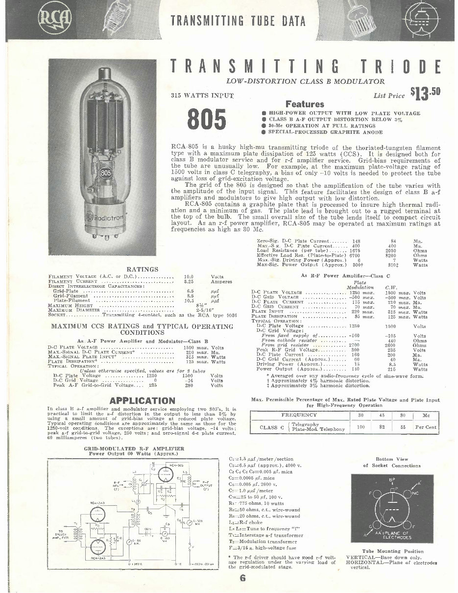
TRANSMITTING TUBE DATA TRANSMITTING TRIODE LOW -DISTORTION CLASS B MODULATOR 315 WATTS INPUT 805 List Price Features $13.50 HIGH -POWER OUTPUT WITH LOW PLATE VOLTAGE CLASS B A -F OUTPUT DISTORTION BELOW 3% 30 -Mc OPERATION AT FULL RATINGS SPECIAL -PROCESSED GRAPHITE ANODE RCA -805 is a husky high -mu transmitting triode of the thoriated-tungsten filament type with a maximum plate dissipation of 125 watts (CCS). It is designed both for class B modulator service and for r -f amplifier service. Grid -bias requirements of the tube are unusually low. For example, at the maximum plate -voltage rating of 1500 volts in class C telegraphy, a bias of only -10 volts is needed to protect the tube against loss of grid- excitation voltage. The grid of the 805 is designed so that the amplification of the tube varies with the amplitude of the input signal. This feature facilitates the design of class B a -f amplifiers and modulators to give high output with low distortion. RCA -805 contains a graphite plate that is processed to insure high thermal radi- ation and a minimum of gas. The plate lead is brought out to a rugged terminal at the top of the bulb. The small overall size of the tube lends itself to compact circuit layout. As an r -f power amplifier, RCA -805 may be operated at maximum ratings at frequencies as high as 30 Mc. Zero -Sig. D -C Plate Current 148 84 Ma. Max. -S g. D -C Plate Current 400 400 Ma. Load Resistance (per tube) 1675 2050 Ohms Effective Load Res. (Plate -to- Plate) 6700 8200 Ohms Max. -Sig. Driving Power (Approx.) 6 7 Watts Max -Sig. Power Output (Approx.) 300t 370$ Watts RATINGS FILAMENT VOLTAGE (A.C. or D.0 ) 10.0 Volts FILAMENT CURRENT 3.25 Amperes DIRECT INTERELECTRODE CAPACITANCES: Grid -Plate 6.5 μμf Grid -Filament 8.5 μμf Plate- Filament 10.5 μμf MAXIMUM HEIGHT 312 MAXIMUM DIAMETER 2- 5/16" SOCKET Transmitting 4- contact, such as the RCA type 0036 MAXIMUM CCS RATINGS and TYPICAL OPERATING CONDITIONS As A -F Power Amplifier and Modulator -Class B D -C PLATE VOLTAGE 1500 max. Volts MAX. -SIGNAL D -C PLATE CURRENT* 210 max. Ma. MAX. -SIGNAL PLATE INPUT* 315 max. Watts PLATE DISSIPATION* 125 max. Watts TYPICAL OPERATION : Unless otherwise specified, values are for 2 tubes As R -F Power Amplifier -Class C Plate Modulation C.W. D -C PLATE VOLTAGE 1250 max. 1500 max. Volts D -C GRID VOLTAGE -500 max. -500 max. Volts D -C PLATE CURRENT 175 max. 210 max. Ma. D -C GRID CURRENT 70 max. 70 max. Ma. PLATE INPUT 220 max. 315 max. Watts PLATE DISSIPATION 85 max. 125 max. Watts TYPICAL OPERATION: D -C Plate Voltage 1250 1500 Volts D -C Grid Voltage: From fixed supply of -160 -105 Volts From cathode resistor - 440 Ohms From grid resistor 2700 2600 Ohms Peak R -F Grid Voltage 300 235 Volts D -C Plate Current 160 200 Ma. D -C Grid Current ( Approx.) 60 40 Ma. Driving Power (Approx.) 16 8.5 Watts Power Output ( Approx.) 140 215 Watts D -C Plate Voltage 1250 1500 Volts D -C Grid Voltage 0 -16 Volts Peak A -F Grid -to -Grid Voltage 235 280 Volts APPLICATION In class B a -f amplifier and modulator service employing two 805's, it is practical to limit the a -f distortion in the output to less than 3% by using a small amount of grid -bias voltage at reduced plate voltage. Typical operating conditions are approximately the same as those for the 1250 -volt conditions. The exceptions are: grid -bias voltage, -14 volts; peak a -f grid -to -grid voltage, 250 volts; and zero -signal d -c plate current, 60 milliamperes (two tubes). GRID -MODULATED R -F AMPLIFIER Power Output 60 Watts (Approx.) TO SPEECH AMPLIFIER (f) RCA -2 AS 0 -100 60 v. R -F output (f) o00 MA -8 í1500V..120 MA * Averaged over any audio -frequency cycle of sine -wave form. t Approximately 4% harmonic distortion. $ Approximately 3% harmonic distortion. Max. Permissible Percentage of Max. Rated Plate Voltage and Plate Input for High- Frequency Operation FREQUENCY 30 45 80 Mc Telegraphy CLASS C { Plate -Mod. Telephony 100 82 55 Per Cent C1=1.5 μμf /meter /section Cz =6.5 μμf (approx.), 4000 v. C3 Cn C0 Co -0.005 μf, mica C5= 0.0005 μf, mica C6 =0.005 μf, 2000 v. C7=1.0 μμf /meter CIO =25 to 50 μf, 100 v. Ri =775 ohms, 10 watts R2 =50 ohms, c.t., wire -wound R3 =20 ohms, c.t., wire -wound LI =R -f choke L2 La =Tune to frequency "f" Tl =lnterstage a -f transformer T2= Modulation transformer F =3/16 a. high -voltage fuse * The r -f driver should have good r -f volt- age regulation under the varying load of the grid -modulated stage. 6 Bottom View of Socket Connections G A/ SA'=PLANE OF ELECTRODES BP P / ` Â NC F Tube Mounting Position VERTICAL -Base down only. HORIZONTAL -Plane of electrodes vertical.
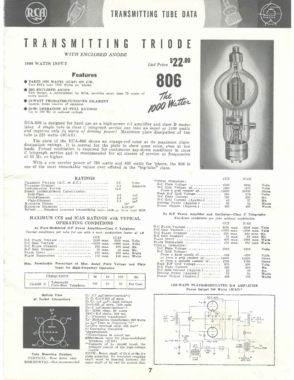
TRANSMITTING TUBE DATA TRANSMITTING TRIODE WITH ENCLOSED ANODE 1000 WATTS INPUT Features TAKES 1000 WATTS (ICAS) ON C.W. Two 806's take 1200 Watts on 'phone. BIG ENCLOSED ANODE This design, a development by RCA, provides more than 75 watts of extra power. 50 -WATT THORIATED -TUNGSTEN FILAMENT Insures great reserve of emission. 30 -Mc OPERATION AT FULL RATINGS Up to 100 Mc at reduced ratings. List Price $2240 806 iw RCA -806 is designed for hard use as a high -power r -f amplifier and class B modu- lator. A single tube in class C telegraph service can take an input of 1000 watts and requires only 34 watts of driving power! Maximum plate dissipation of the tube is 225 watts (ICAS). The plate of the RCA -806 shows an orange -red color at its maximum plate - dissipation ratings. It is normal for the plate to show some color, even at low loads. Forced ventilation is required for continuous key -down conditions in class C telegraph service and is recommended for all classes of service at frequencies of 30 Mc. or higher. With a c -w carrier power of 780 watts and 460 watts for 'phone, the 806 is one of the most remarkable values ever offered in the "big- tube" class. RATINGS FILAMENT VOLTAGE (A.C. OR D.0 ) 5.0 Volts FILAMENT CURRENT 9.5 Amperes AMPLIFICATION FACTOR 12.6 DIRECT INTERELECTRODE CAPACITANCES: Grid -Plate 4.0 μμf Grid -Filament 5.6 μμf Plate- Filament 0.4 μμf MAXIMUM HEIGHT 10" MAXIMUM DIAMETER 343/16" SOCKET Standard 4- contact transmitting type, such as ACA type 9936 TYPICAL OPERATION: D -C Plate Voltage D -C Grid Voltage of From a grid resistor of Peak R -F Grid Voltage D -C Plate Current D -C Grid Current ( Approx.) Driving Power (Approx.) Power Output ( Approx.) As R -F Power Amplifier and CCS 2500 -600 15000 890 195 40 32 390 Oscillator -Class ICAS 3000 Volta -670 Volta 25000 Ohms 970 Volta 195 Ma. 27 Ma. 24 Watts 460 Watts C Telegraphy MAXIMUM CCS and ICAS RATINGS with TYPICAL OPERATING CONDITIONS As Plate -Modulated R -F Power Amplifier -Class C Telephony Carrier conditions per tube for use with a max. modulation factor of 1.1 CCS ICAS D -C PLATE VOLTAGE 2500 max. 3000 max. Volts D -C GRID VOLTAGE -1000 max. -1000 max. Volts D -C PLATE CURRENT 200 max. 200 max. Ma. D -C GRID CURRENT 50 max. 50 max. Ma. PLATE INPUT 500 max. 600 max. Watts PLATE DISSIPATION 110 max. 150 max. Watts Max. Permissible Percentage of Max. Rated Plate Voltage and Plate Input for High- Frequency Operation FREQUENCY 30 50 100 Mc CLASS C { Telegraphy Plate -Mod. Telephony 100 80 50 Per Cent Bottom View of Socket Connections Tube Mounting Position VERTICAL -Base down only HORIZONTAL -Not recommended Ca =0.7 μμf /meter /section *+ C2 Cs C4 =0.005 μf mica Cs Cc= 4.0 μμf *, high voltage C7=0.002 μf mica, 7500 volts Cs =1 μμf /meter /section *+ RT =12500 ohms, 80 watts RFC =R -f choke, 500 ma. TI =Filament transformer Ts= Modulation transformer, 600 watts L1 Ls =Tune to frequency "f" 1,3=D-c overload relay, 600 ma ** f= Operating frequency *Approximate +Capacitance in actual use #Maximum value for plate- modulated telephony (ICAS) * *Contacts of La should break the primary circuit of the high -voltage supply NOTE : Rotor shaft of Cs is at the d -c plate potential. An insulated coupling shaft must be inserted between the rotor shaft of Cs and its control dial. 7 Key -down conditions per tube without modulation ccs D -C PLATE VOLTAGE 3000 max. D -C GRID VOLTAGE 1000 max. D -C PLATE CURRENT 200 max. D -C GRID CURRENT 50 max. PLATE INPUT 600 max. PLATE DISSIPATION 150 max. TYPICAL OPERATION: D -C Plate Voltage D -C Grid Voltage: From a fixed supply of or from a grid resistor of or from a cathode resistor of Peak R -F Grid Voltage D -C Plate Current D -C Grid Current (Approx.) Driving Power (Approx.) Power Output (Approx.) ICAS 3300 max. Volts -1000 max. Volta 300 max. Ma. 50 max. Ma. 1000 max. Watts 225 max. Watts 3000 3300 Volta -600 -600 Volts 24000 15000 Ohms 2700 1730 Ohms 870 930 Volts 195 300 Ma. 25 40 Ma. 20 34 Watts 450 780 Watts 1200 -WATT PLATE -MODULATED R -F AMPLIFIER Power Output 900 Watts (ICAS)* R -F INPUT (f) IC1=55 RCA 806 2 T c ce - - 1:1 V 0-200 e6 RCA-'806 -0 - L EOUTPR -F OT (f) LINE o- 0 0 M 7700 OHMS +3000 V.tt 400 MA. TO 00uLAT0R
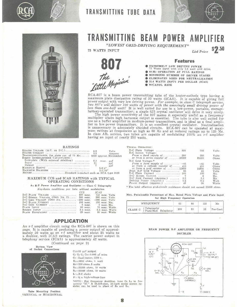
TRANSMITTING TUBE DATA TRANSMITTING BEAM POWER AMPLIFIER "LOWEST GRID -DRIVING REQUIREMENT" 75 WATTS INPUT 807 II zdt,4/1/11(44.411 List Price Features $2 50 EXTREMELY LOW DRIVING POWER 75 Watts input with only 0.2 watt grid drive. 60 -Mc OPERATION AT FULL RATINGS MINIMIZES NUMBER OF DRIVER STAGES ELIMINATES NEED FOR NEUTRALIZATION 21.4 WATTS INPUT PER DOLLAR (ICAS) MICANOL BASE RCA -807 is a beam power transmitting tube of the heater -cathode type having a maximum plate dissipation rating of 30 watts (ICAS). It is capable of giving full power output with very low driving power. For example, in class C telegraph service, two 807's will deliver 100 watts of power with the amazingly small driving power of less than one -half watt! It is well suited for use in a low- power, portable, storage - battery- operated transmitter; a single 6J5 crystal oscillator will drive it very nicely. The high power sensitivity of the 807 makes it especially useful as a frequency multiplier where high harmonic output is essential. The tube is also well suited for use as a buffer amplifier in medium -power transmitters, and is ideal as a final ampli- fier in low -power transmitters. It is an excellent crystal oscillator. Neutralization is unnecessary in adequately shielded circuits. RCA -807 can be operated at maxi- mum ratings at frequencies as high as 60 Mc and at reduced ratings up to 125 Mc. In class AB_ service, two tubes are capable of modulating 100% an r -f amplifier having an input of nearly 250 watts. RATINGS TYPICAL OPERATION : HEATER VOLTAGE (A.C. OR D.0 ) 6.3 Volts HEATER CURRENT 0.9 Ampere TRANSCONDUCTANCE, for plate cur, of 72 Ma 6000 approx. Micromhos D -C Plate Voltage Screen Voltage: From a fixed supply of 600 250 750 250 Volts Volts DIRECT INTEEELECTRODE CAPACITANCES: or from a series resistor of 50000 85000 Ohms Grid -plate (With external shielding) 0.2 max. μμf D -C Grid Voltage:' Input 11 μμf From a fixed supply of -45 -45 Volts Output 7 μμf or from a cathode resistor of 410 410 Ohms MAXIMUM HEIGHT 5 -3'4" or from a grid resistor of 12800 12800 Ohms MAXIMUM DIAMETER 2-1/16" Peak R -F Grid Voltage 65 65 Volts SOCKET ....Standard 5- contact such as RCA type 9920 D -C Plate Current 100 100 Ma. D -C Screen Current 7 6 Ma. MAXIMUM CCS and ICAS RATINGS with TYPICAL D -C Grid Current (Approx.) 3.5 3.5 Ma. OPERATING CONDITIONS Driving Power (Approx.) Power Output (Approx.) 0.2 40 0.2 50 Watt Watts As R -F Power Amplifier and Oscillator - Class C Telegraphy Key -down conditions per tube without modulation CCS ICAS D -C PLATE VOLTAGE 600 max. 750 max. Volts D -C SCREEN VOLTAGE (GRID No. 2) 300 max. 300 max. Volts D -C GRID VOLTAGE (GRID No. 1) -200 max. -200 max. Volts D -C PLATE CURRENT 100 max. 100 max. Ma. D -C GRID CURRENT 5 max. 5 max. Ma. PLATE INPUT 60 max. 75 max. Watts SCREEN INPUT 3.5 max. 3.5 max. Watts PLATE DISSIPATION 25 max. 30 max. Watts APPLICATION An r -f amplifier circuit using the RCA -807 is shown on this page. It is capable of producing a power output of approxi- mately 50 watts as an r -f amplifier and about 25 watts as a doubler, with ICAS ratings. The carrier power output in telephony service (ICAS) is approximately 42 watts. (Continued on page 9) Bottom View of Socket Connections Tube Mounting Position VERTICAL or HORIZONTAL * The total effective grid- circuit resistance should not exceed 25000 ohms. Max. Permissable Percentage of Max. Rated Plate Voltage and Plate Input for High Frequency Operation FREQUENCY 60 80 125 Mc CLASS C ( Telegraphy j Plate -Mod. Telephony 100 80 55 Per Cent CI =50 μμf midget Cs Cs C4 Ce =0.005 μf mica Cs =2μμf /meter, 1200 v. RI =6000 ohms, 1 watt R2 =250 ohms, 5 watts Rs =35000 ohms, 10 watts R4 =20000 ohms, 10 watts LI =R -f choke F =I/s a. high -voltage fuse NOTE: For frequency doubling, tune Cs Ls to fre- quency "2f." A 50,000 -ohm, 10 -watt series screen re- sistor can be used in place of Rs and R4. 8 BEAM POWER R -F AMPLIFIER OR FREQUENCY DOUBLER CI R -F INPUT (f) o-io MA. 42aoV. (APPROX.) 2 E///- R -F OUT PUT (f OR 2f ) 0 -200 MA. + 600 V.
A great reference for the builder and experimenter in the field of Radio, Television, Transmitters, Amplifiers, Detectors, RF amplifiers, CB Radio, Radios, Marine Radio, and more. This catalog is available in .PDF format for instant accessing and viewing. It is also instantly deliverable via email, printable, and can be securely purchased via PayPal by clicking on the green button above.
For more items for sale, visit the E-Book shop for a wide range of manuals and guides including Honda Motorcycle ATV TRX, Polaris ATV snowmobile, rain showers to relax mp3, kerosene heaters, raising chickens, wilderness survival, diesel engine repair, solar cookers, preserving and canning guides, electric motor and generators, hydro-electric, two-stroke engine repair, making rockets, small engine repair, meat, beef, pork, and sausage recipes, dehydrating fruits and vegetables, fish and meat, edible wild mushrooms guide, poisonous plants and animals, making moonshine and still how-to guide, electronics training, radio and TV courses, steam engines, aircraft manuals, survival prepping preppers guide, boys books, navy torpedoes, shortwave radio, understanding electron vacuum tubes, tube manuals, radio and TV, amplifier circuits and schematics, World War 2 information, and more.
Workshop manual
Electrical
Specs
Tires
Cylinder head
Crankshaft
Fuel tank
Carburetor
Instructions
Jeep overhaul
Pads
Four
Coolant change
Camshaft
Tire
Plastics
Which engine oil
Bore
Charging
Operation
Starter
Diagram
Transmission
Main jet
Piston
Rings
Compression
Brakes
Torque
Assembly
Disassembly
Alternator
Wiring
Generator
70
90
125
175
200
250
300
350
400
420
450
500
550
650
680
750
800
900
1000
1100
1800
IQ
FE
FM
XX
XP
Shovelhead
RZR
EX
TwinStar
Rebel
NightHawk
Quality
Instant
1959-2015
Recently Viewed
5,521,897Happy Clients
2,594,462eManuals
1,120,453Trusted Sellers
15Years in Business
Price:
Actual Price:
RCA TRANSMITTING ELECTRON VACUUM TUBE Catalog Radio Book