



il
Receiving
Tube
Manual
T
Including Picture
Tubes and Industrial
Receiving Tubes
-
ItCJl
Receiving
Tlibe
Manual
Including Picture
Tubes and Industrial
Receiving Tubes
THIS MANUAL, like its many predecessors, has been prepared to
assist those who work or experiment with home-entertainment or
industrial receiving types of electron tubes and circuits or with tele-
vision picture tubes. It will be found valuable by engineers, service
technicians, educators, experimenters, electricians, radio amateurs,
hobbyists, students, and others interested in electron tubes and their
applications.
Easy-to-read chapters explain the basic principles of operation, sig-
nificant electrical characteristics, circuit applications, and testing of
various types of electron tubes. Technical data are given on current
RCA home-entertainment and industrial receiving-type tubes and on
picture tubes. Circuit diagrams are given illustrating the use of RCA
tubes in many practical applications. Also included are expanded and
updated replacement guides for obsolete or hard-to-find industrial
and home-entertainment receiving tubes.
RCA Distributor and Special Products Division
Cherry Hill Offices
|
Camden, N.J. 08101
Copyright 1975 by RCA Corporation
(All rights reserved under Pan-American Copyright Convention)
Printed in U.S.A. 8/75
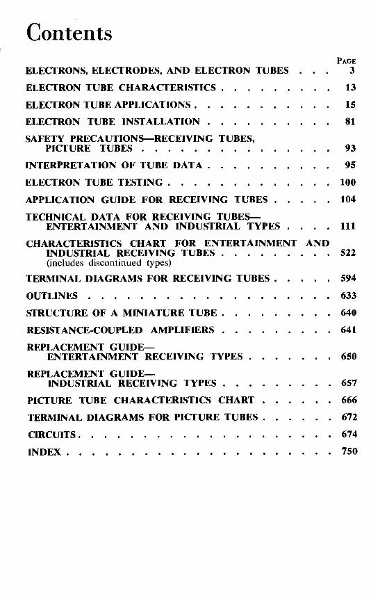
Contents
Page
ELECTRONS, ELECTRODES, AND ELECTRON TUBES ... 3
ELECTRON TUBE CHARACTERISTICS 13
ELECTRON TUBE APPLICATIONS 15
ELECTRON TUBE INSTALLATION 81
SAFETY PRECAUTIONS—RECEIVING TUBES,
PICTURE TUBES 93
INTERPRETATION OF TUBE DATA 95
ELECTRON TUBE TESTING 100
APPLICATION GUIDE FOR RECEIVING TUBES 104
TECHNICAL DATA FOR RECEIVING TUBES-
ENTERTAINMENT AND INDUSTRIAL TYPES .... Ill
CHARACTERISTICS CHART FOR ENTERTAINMENT AND
INDUSTRIAL RECEIVING TUBES 522
(includes discontinued types)
TERMINAL DIAGRAMS FOR RECEIVING TUBES 594
OUTLINES 633
STRUCTURE OF A MINIATURE TUBE 640
RESISTANCE-COUPLED AMPLIFIERS 641
REPLACEMENT GUIDE-
ENTERTAINMENT RECEIVING TYPES 650
REPLACEMENT GUIDE-
INDUSTRIAL RECEIVING TYPES 657
PICTURE TUBE CHARACTERISTICS CHART 666
TERMINAL DIAGRAMS FOR PICTURE TUBES 672
CIRCUITS 674
INDEX 750
Information furnished by RCA is believed to be accurate and reliable. However, no responsi-
bility is assumed by RCA for its use; nor for any infringements of patents or other rights of
third parties which may result from its use. No license is granted by implication or otherwise
under any patent or patent rights of RCA
3
Electrons, Electrodes
and Electron Tubes
THE
electron tube is a marvelous
device. It makes possible the per-
forming of operations, amazing in con-
ception, with a precision and a certainty
that are astounding. It is an exceedingly
sensitive and accurate instrument—the
product of coordinated efforts of engi-
neers and craftsmen. Its construction
requires materials from every corner
of the earth. Its use is world-wide.
The importance of the electron
tube lies in its ability to control almost
instantly the flight of the millions of
electrons supplied by the cathode. It
accomplishes this control with a mini-
mum of energy. Because it is almost
instantaneous in its action, the electron
tube can operate efficiently and accu-
rately at extremely high electrical fre-
quencies.
Electrons
All matter exists in the solid,
liquid, or gaseous state. These three
forms consist entirely of minute divi-
sions known as molecules, which, in
turn, are composed of atoms. Atoms
have a nucleus which is a positive
charge of electricity, around which re-
volve tiny charges of negative electricity
known as electrons. Scientists have es-
timated that electrons weigh only 1/30-
billion, billion, billion, billionths
(%o x 10
M
) of an ounce, and that they
may travel at speeds of thousands of
miles per second.
Electron movement may be accele-
rated by the addition of energy. Heat is
one form of energy which can be con-
veniently used to speed up the electron.
For example, if the temperature of a
metal is gradually raised, the electrons
in the metal gain velocity. When the
metal becomes hot enough, some elec-
trons may acquire sufficient speed to
break away from the surface of the
metal. This action, which is accelerated
when the metal is heated in a vacuum,
is utilized in most electron tubes to
produce the necessary electron supply.
An electron tube consists of a
cathode, which supplies electrons, and
one or more additional electrodes,
which control and collect these elec-
trons, mounted in an evacuated en-
velope. The envelope may be made of
glass, metal, ceramic, or a combination
of these materials.
Cathodes
A cathode is an essential part of an
electron tube because it supplies the
electrons necessary for tube operation.
When energy in some form is applied
to the cathode, electrons are released.
Heat is the form of energy generally
used. The method of heating the cath-
ode may be used to distinguish between
the different forms of cathodes. For ex-
ample, a directly heated cathode, or
filament-cathode, is a wire heated by
the passage of an electric current. An
indirectly heated cathode, or heater-
cathode, consists of a filament, or
heater, enclosed in a metal sleeve. The
sleeve carries the electron-emitting ma-
terial on its outside surface and is
heated by radiation and conduction
from the heater.
A filament, or directly heated cath-
ode, such as that shown in Fig. 1 may
4
RCA Receiving Tube Manual
be further classified by identifying the
filament or electron-emitting material.
The materials in regular use are tung-
sten, thoriated tungsten, and metals
which have been coated with alkaline-
earth oxides. Tungsten filaments are
made from the pure metal. Because
they must operate at high temperatures
(a dazzling white) to emit sufficient
electrons, a relatively large amount of
filament power is required.
Thoriated-tungsten filaments are
made from tungsten impregnated with
thorium oxide. Due to the presence of
thorium, these filaments liberate elec-
trons at a more moderate temperature
of about 1700°C (a bright yellow) and
are, therefore, much more economical
of filament power than are pure tung-
sten filaments.
Alkaline earths are usually applied
as a coating on a nickel-alloy wire or
ribbon. This coating, which is dried in
a relatively thick layer on the filament,
requires only a relatively low tempera-
ture of about 700-750°C (a dull red)
to produce a copious supply of elec-
trons. Coated filaments operate very
efficiently and require relatively little
filament power. However, each of these
cathode materials has special advan-
tages which determine the choice for a
particular application.
Directly heated filament-cathodes
require comparatively little heating
power. They are used in tube types de-
signed for battery operation because it
is, of course, desirable to impose as
small a drain as possible on the bat-
teries. They are also used in rectifiers
such as the 1G3GTA/1B3GT and the
5Y3GT.
An indirectly heated cathode, or
heater-cathode, consists of a thin metal
sleeve coated with electron-emitting ma-
terial such as alkaline-earth oxides. The
emissive surface of the cathode is main-
tained at the required temperature
(approximately 1050°K) by resistance-
heating of a tungsten or tungsten-alloy
wire which is placed inside the cath-
ode sleeve and electrically insulated
from it. as shown in Fig. 2. The heater
is used only for the purpose of heat-
ing the cathode sleeve and sleeve coat-
ing to an electron-emitting temperature.
Useful emission does not take place
from the heater wire.
A new dark heater insulating coat-
ing developed by RCA has better heat
transfer than earlier aluminum-oxide
coatings, and makes it possible to oper-
ate heaters at lower temperatures for
given power inputs. Because the tensile
strength of the heater wire increases
at the lower operating temperatures,
tubes using dark heaters have increased
reliability, stability, and life.
Fig. I
—
Filament Fig. 2
—
Indirectly
or directly heated heated cathode or
cathode. heater-cathode.
The heater-cathode construction is
well adapted for use in electron tubes
intended for operation from ac power
lines and from storage batteries. The
use of separate parts for emitter and
heater functions, the electrical insula-
tion of the heater from the emitter,
and the shielding effect of the sleeve
may all be utilized in the design of the
tube to minimize the introduction of
hum from the ac heater supply and to
minimize electrical interference which
might enter the tube circuit through the
heater-supply line. From the viewpoint
of circuit design, the heater-cathode
construction offers advantages in con-
nection flexibility because of the elec-
trical separation of the heater from the
cathode.
Another advantage of the heater-
cathode construction is that it makes
practical the design of a rectifier tube
having close spacing between its cath-
ode and plate, and of an amplifier tube
having close spacing between its cath-
ode and grid. In a close-spaced rectifier
tube, the voltage drop in the tube is
low, and, therefore, the regulation is
improved. In an amplifier tube, the
close spacing increases the gain obtain-
able from the tube. Because of the
Electrons, Electrodes and Electron Tubes 5
advantages of the heater-cathode con-
struction, almost all present-day receiv-
ing tubes designed for ac operation
have heater-cathodes.
Generic Tube Types
Electrons are of no value in an
electron tube unless they can be put to
work. Therefore, a tube is designed
with the parts necessary to utilize elec-
trons as well as those required to pro-
duce them. These parts consist of a
cathode and one or more supplemen-
tary electrodes. The electrodes are en-
closed in an evacuated envelope having
the necessary connections brought out
through air-tight seals. The air is re-
moved from the envelope to allow free
movement of the electrons and to pre-
vent injury to the emitting surface of
the cathode.
When the cathode is heated, elec-
trons leave the cathode surface and
form an invisible cloud in the space
around it. Any positive electric poten-
tial within the evacuated envelope of-
fers a strong attraction to the electrons
(unlike electric charges attract; like
charges repel). Such a positive electric
potential can be supplied by an anode
(positive electrode) located within the
tube in proximity to the cathode.
Diodes
The simplest form of electron tube
contains two electrodes, a cathode and
an anode (plate), and is often called a
diode, the family name for a two-elec-
trode tube. In a diode, the positive
potential is supplied by a suitable elec-
trical source connected between the
plate terminal and a cathode terminal,
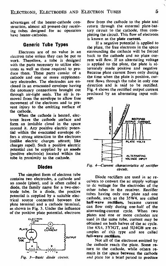
as shown in Fig. 3. Under the influence
of the positive plate potential, electrons
)OUTPUT
Fig. 3
—
Basic diode
flow from the cathode to the plate and
return through the external plate-bat-
tery circuit to the cathode, thus com-
pleting the circuit. This flow of electrons
is known as the plate current.
If a negative potential is applied to
the plate, the free electrons in the space
surrounding the cathode will be forced
back to the cathode and no plate cur-
rent will flow. If an alternating voltage
is applied to the plate, the plate is al-
ternately made positive and negative
Because plate current flows only during
the time when the plate is positive, cur-
rent flows through the tube in only one
direction and is said to be rectified.
Fig. 4 shows the rectified output current
produced by an alternating input volt-
age.
Fig. 4
—
Current characteristics of rectifier
circuit.
Diode rectifiers are used in ac re-
ceivers to convert the ac supply voltage
to dc voltage for the electrodes of the
other tubes in the receiver. Rectifier
tubes having only one plate and one
cathode, such as the 35W4, are called
half-wave rectifiers, because current
can flow only during one-half of the
alternating-current cycle. When two
plates and one or more cathodes are
used in the same tube, current may be
obtained on both halves of the ac cycle.
The 6X4, 5Y3GT, and 5U4GB are ex-
amples of this type and are called
full-wave rectifiers.
Not all of the electrons emitted by
the cathode reach the plate. Some re-
turn to the cathode, while others re-
main in the space between the cathode
and plate for a brief period to produce
6 RCA Receiving Tube Manual
an effect known as space charge. This
charge has a repelling action on other
electrons which leave the cathode sur-
face and impedes their passage to the
plate. The extent of this action and the
amount of space charge depend on the
cathode temperature, the distance be-
tween the cathode and the plate, and
the plate potential. The higher the plate
potential, the less is the tendency for
electrons to remain in the space-charge
region and repel other electrons. This
effect may be noted by applying increas-
ingly higher plate voltages to a tube
operating at a fixed heater or filament
voltage. Under these conditions, the
maximum number of available electrons
is fixed, but increasingly higher plate
voltages will succeed in attracting a
greater proportion of the free electrons.
Beyond a certain plate voltage,
however, additional plate voltage has
little effect in increasing the plate cur-
rent because all of the electrons emitted
by the cathode are already being drawn
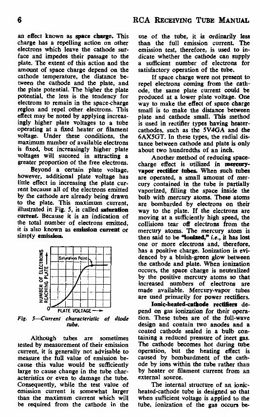
to the plate. This maximum current,
illustrated in Fig. 5, is called saturation
current. Because it is an indication of
the total number of electrons emitted,
it is also known as emission current or
simply emission.
Sat rati m P )int
°
PLATE VOLTAGE
—»-
Fig. 5
—
Current characteristic of diode
tube.
Although tubes are sometimes
tested by measurement of their emission
current, it is generally not advisable to
measure the full value of emission be-
cause this value would be sufficiently
large to cause change in the tube char-
acteristics or even to damage the tube.
Consequently, while the test value of
emission current is somewhat larger
than the maximum current which will
be required from the cathode in the
use of the tube, it is ordinarily less
than the full emission current The
emission test, therefore, is used to in-
dicate whether the cathode can supply
a sufficient number of electrons for
satisfactory operation of the tube.
If space charge were not present to
repel electrons coming from the cath-
ode, the same plate current could be
produced at a lower plate voltage. One
way to make the effect of space charge
small is to make the distance between
plate and cathode small. This method
is used in rectifier types having heater-
cathodes, such as the 5V4GA and the
6AX5GT. In these types, the radial dis-
tance between cathode and plate is only
about two hundredths of an inch.
Another method of reducing space-
charge effect is utilized in mercury-
vapor rectifier tubes. When such tubes
are operated, a small amount of mer-
cury contained in the tube is partially
vaporized, filling the space inside the
bulb with mercury atoms. These atoms
are bombarded by electrons on their
way to the plate. If the electrons are
moving at a sufficiently high speed, the
collisions tear off electrons from the
mercury atoms. The mercury atom is
then said to be "ionized," i.e., it has lost
one or more electrons and, therefore,
has a positive charge. Ionization is evi-
denced by a bluish-green glow between
the cathode and plate. When ionization
occurs, the space charge is neutralized
by the positive mercury atoms so that
increased numbers of electrons are
made available. Mercury-vapor tubes
are used primarily for power rectifiers.
Ionic-heated-cathode rectifiers de-
pend on gas ionization for their opera-
tion. These tubes are of the full-wave
design and contain two anodes and a
coated cathode sealed in a bulb con-
taining a reduced pressure of inert gas.
The cathode becomes hot during tube
operation, but the heating effect is
caused by bombardment of the cath-
ode by ions within the tube rather than
by heater or filament current from an
external source.
The internal structure of an ionic-
heated-cathode tube is designed so that
when sufficient voltage is applied to the
tube, ionization of the gas occurs be-
Electrons, Electrodes and Electron Tubes 7
tween the anode which is instan-
taneously positive and the cathode.
Under normal operating voltages, ioni-
zation does not take place between the
anode that is negative and the cathode,
so that the requirements for rectifica-
tion are satisfied. The initial small flow
of current through the tube is sufficient
to raise the cathode temperature quickly
to incandescence, whereupon the cath-
ode emits electrons. The voltage drop
in such tubes is slightly higher than
that of the usual hot-cathode gas rec-
tifiers because energy is taken from the
ionization discharge to keep the cath-
ode at operating temperature. Proper
operation of these rectifiers requires a
minimum flow of load current at all
times to maintain the cathode at the
temperature required to supply sufficient
emission.
Triodes
When a third electrode, called the
control grid, is placed between the cath-
ode and plate, the tube is known as a
triode, the family name for a three-
electrode tube. The grid usually consists
of relatively fine wire wound on two
support rods (siderods) and extending
the length of the cathode. The spacing
between turns of wire is large compared
with the size of the wire so that the
passage of electrons from cathode to
plate is practically unobstructed by the
grid. In some types, a frame grid is used.
The frame consists of two siderods sup-
ported by four metal straps. Extremely
fine lateral wire (diameter of 0.5 mil or
less) is wound under tension around the
frame. This type of grid permits the
use of closer spacings between grid
wires and between tube electrodes, and
thus improves tube performance.
The purpose of the grid is to con-
trol the flow of plate current. When a
tube is used as an amplifier, a negative
dc voltage is usually applied to the
grid. Under this conditon the grid does
not draw appreciable current.
The number of electrons attracted
to the plate depends on the combined
effect of the grid and plate polarities, as
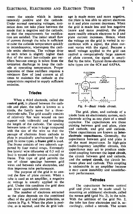
shown in Fig. 6. When the plate is posi-
tive, as is normal, and the dc grid volt-
age is made more and more negative,
the plate is less able to attract electrons
to it and plate current decreases. When
the grid is made less and less negative
(more and more positive), the plate
more readily attracts electrons to it and
plate current increases. Hence, when
the voltage on the grid is varied in ac-
cordance with a signal, the plate cur-
rent varies with the signal. Because a
small voltage applied to the grid can
control a comparatively large amount
of plate current, the signal is ampli-
fied by the tube. Typical three-electrode
tube types are the 6C4 and 6AF4A.
ELECTRON
FLOW
Fig. 6
—
Basic triode circuit.
The grid, plate, and cathode of a
triode form an electrostatic system, each
electrode acting as one plate of a small
capacitor. The capacitances are those
existing between grid and plate, plate
and cathode, and grid and cathode.
These capacitances are known as inter-
electrode capacitances. Generally, the
capacitance between grid and plate is
of the most importance. In high-gain
radio-frequency amplifier circuits, this
capacitance may act to produce unde-
sired coupling between the input circuit,
the circuit between grid and cathode,
and the output circuit, the circuit be-
tween plate and cathode. This coupling
is undesirable in an amplifier because
it may cause instability and unsatisfac-
tory performance.
Tetrodes
The capacitance between control
grid and plate can be made small by
mounting an additional electrode, called
the screen grid (grid No. 2), in the tube.
With the addition of the grid No. 2,
the tube has four electrodes and is, ac-
cordingly, called a tetrode. The screen
8 RCA Receiving Tube Manual
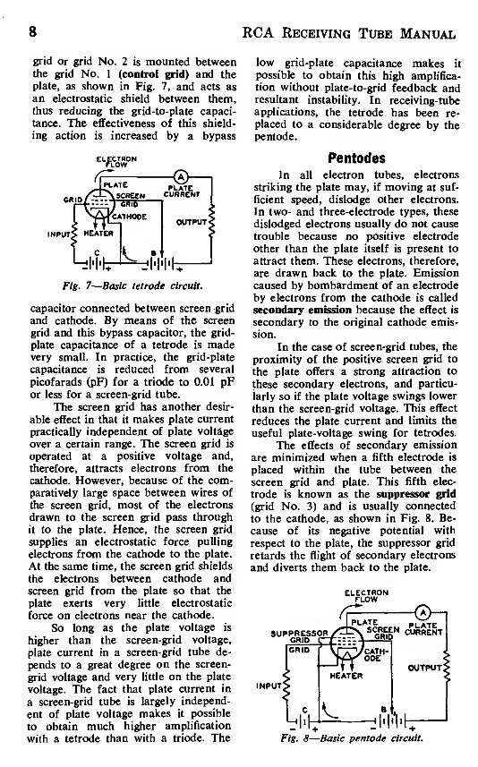
grid or grid No. 2 is mounted between
the grid No. 1 (control grid) and the
plate, as shown in Fig. 7, and acts as
an electrostatic shield between them,
thus reducing the grid-to-plate capaci-
tance. The effectiveness of this shield-
ing action is increased by a bypass
INPUT'
Fig. 7
—
Basic tetrode circuit.
capacitor connected between screen grid
and cathode. By means of the screen
grid and this bypass capacitor, the grid-
plate capacitance of a tetrode is made
very small. In practice, the grid-plate
capacitance is reduced from several
picofarads (pF) for a triode to 0.01 pF
or less for a screen-grid tube.
The screen grid has another desir-
able effect in that it makes plate current
practically independent of plate voltage
over a certain range. The screen grid is
operated at a positive voltage and,
therefore, attracts electrons from the
cathode. However, because of the com-
paratively large space between wires of
the screen grid, most of the electrons
drawn to the screen grid pass through
it to the plate. Hence, the screen grid
supplies an electrostatic force pulling
electrons from the cathode to the plate.
At the same time, the screen grid shields
the electrons between cathode and
screen grid from the plate so that the
plate exerts very little electrostatic
force on electrons near the cathode.
So long as the plate voltage is
higher than the screen-grid voltage,
plate current in a screen-grid tube de-
pends to a great degree on the screen-
grid voltage and very little on the plate
voltage. The fact that plate current in
a screen-grid tube is largely independ-
ent of plate voltage makes it possible
to obtain much higher amplification
with a tetrode than with a triode. The
low grid-plate capacitance makes it
possible to obtain this high amplifica-
tion without plate-to-grid feedback and
resultant instability. In receiving-tube
applications, the tetrode has been re-
placed to a considerable degree by the
pentode.
Pentodes
In all electron tubes, electrons
striking the plate may, if moving at suf-
ficient speed, dislodge other electrons.
In two- and three-electrode types, these
dislodged electrons usually do not cause
trouble because no positive electrode
other than the plate itself is present to
attract them. These electrons, therefore,
are drawn back to the plate. Emission
caused by bombardment of an electrode
by electrons from the cathode is called
secondary emission because the effect is
secondary to the original cathode emis-
sion.
In the case of screen-grid tubes, the
proximity of the positive screen grid to
the plate offers a strong attraction to
these secondary electrons, and particu-
larly so if the plate voltage swings lower
than the screen-grid voltage. This effect
reduces the plate current and limits the
useful plate-voltage swing for tetrodes.
The effects of secondary emission
are minimized when a fifth electrode is
placed within the tube between the
screen grid and plate. This fifth elec-
trode is known as the suppressor grid
(grid No. 3) and is usually connected
to the cathode, as shown in Fig. 8. Be-
cause of its negative potential with
respect to the plate, the suppressor grid
retards the flight of secondary electrons
and diverts them back to the plate.
SUPPRESSOR
GRID
—
INPUT
Fig. 8
—
Basic pentode circuit.
Electrons, Electrodes and Electron Tubes 9
The family name for a five-elec-
trode tube is "pentode." In power-out-
put pentodes, the suppressor grid makes
possible higher power output with lower
grid-driving voltage; in radio-frequency
amplifier pentodes, the suppressor grid
makes possible high voltage amplifica-
tion at moderate values of plate volt-
age. These desirable features result
from the fact that the plate-voltage
swing can be made very large. In fact,
the plate voltage may be as low as,
or lower than, the screen-grid voltage
without serious loss in signal-gain capa-
bility. Representative pentodes used for
power amplification are the 6CL6 and
6K6GT; representative pentodes used
for voltage amplification are the 6AU6A,
6BA6, and 5879.
Beam Power Tubes
A beam power tube is a tetrode or
pentode in which directed electron
beams are used to increase substantially
the power-handling capability of the
tube. Such a tube contains a cathode,
a control grid (grid No. 1), a screen
grid (grid No. 2), a plate, and, op-
tionally, a suppressor grid (grid No. 3).
When a beam power tube is designed
without an actual suppressor grid, the
electrodes are so spaced that secondary
emission from the plate is suppressed
by space-charge effects between screen
grid and plate. The space charge is
produced by the slowing up of electrons
traveling from a high-potential screen
grid to a lower-potential plate. In this
low-velocity region, the space charge
produced is sufficient to repel second-
ary electrons emitted from the plate
and to cause them to return to the
plate.
Beam power tubes of this design
employ beam-confining electrodes at
cathode potential to assist in producing
the desired beam effects and to prevent
stray electrons from the plate from re-
turning to the screen grid outside of the
beam. A feature of a beam power tube
is its low screen-grid current. The screen
grid and the control grid are spiral wires
wound so that each turn of the screen
grid is shaded from the cathode by a
grid turn. This alignment of the screen
grid and control grid causes the elec-
trons to travel in sheets between the
turns of the screen grid so that very
few of them strike the screen grid.
Because of the effective suppressor ac-
tion provided by space charge and be-
cause of the low current drawn by the
screen grid, the beam power tube has
the advantages of high power output,
high power sensitivity, and high effi-
ciency.
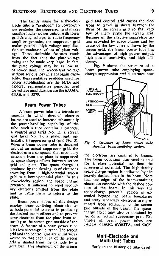
Fig. 9 shows the structure of a
beam power tube employing space-
charge suppression »ncl illustrates how
Fig. 9
—
Structure of beam power tube
showing beam-confining action.
the electrons are confined to beams.
The beam condition illustrated is that
for a plate potential less than the
screen-grid potential. The high-density
space-charge region is indicated by the
heavily dashed lines in the beam. Note
that the edges of the beam-confining
electrodes coincide with the dashed por-
tion of the beam. In this way the
space-charge potential region is ex-
tended beyond the beam boundaries
and stray secondary electrons are pre-
vented from returning to the screen
grid outside of the beam. The space-
charge effect may also be obtained by
use of an actual suppressor grid. Ex-
amples of beam power tubes are
6AQ5A, 6L6GC, 6V6GTA, and 50C5.
Multi-Electrode and
Multi-Unit Tubes
Early in the history of tube devel-
You're Reading a Preview
What's Included?
 Lifetime Access
Fast Download Speeds
Online & Offline Access
Access PDF Contents & Bookmarks
Full Search Facility
Print one or all pages of your manual
$27.99
RCA Receiving Tube RC-30 Technical Manual
Viewed 52 Times Today

What's Included?
Lifetime Access
Fast Download Speeds
Online & Offline Access
Access PDF Contents & Bookmarks
Full Search Facility
Print one or all pages of your manual
$27.99

Secure transaction
What's Included?
Lifetime Access
Fast Download Speeds
Online & Offline Access
Access PDF Contents & Bookmarks
Full Search Facility
Print one or all pages of your manual
Description
The 1975 RCA Receiving Tube Manual, Technical Series RC-30. Comprehensive 762-page technical reference covering receiving vacuum tubes including types not found in RC-19: 6CA7/EL34, 5AR4/GZ34, 6DJ8, 6DN7, 6LF6, 6KG6A/EL509, 6550, 7189, 7591, 7868, and industrial receiving tubes.
Includes full technical specifications, operating characteristics, and application data for each tube type. An essential reference for technicians, audio engineers, and electronics professionals working with valve-based equipment. Available in PDF format, searchable and printable.


