


introduction
No part of this document may be reproduced or transmitted in any form or by any means,
electronic or mechanical, for any purpose, without the express written permission of
International Audio Group Limited (IAG).
This manual is for the exclusive use of I AG, its approved distributors and approved
UK service agents.
No part of this manual shall be transferred to a third party without the written permission of I AG.
It is the responsibility of the user to ensure that all the information contained in this manual
is current. Notification for new issues of this manual and minor updates will be given via
the I AG web-site or on request.
This manual has been prepared with the greatest care, it is intended for information only
and no liability shall be accepted for errors or changes to specification.
For further service information, parts lists and updates, please contact our web-site.
© 2005 International Audio Group Limited. All rights reserved.
Notification for new issues of this service manual will
be given via the Audiolab web site:-
issue number :- 2005/001/8000P GRP00003.0 01 1
issue date :- September 04 2005 2 25 5. .0 01 1. .1 19 99 99 9

index
1.0 safety and servicing notes
1.1 Safety precautions ....................................................................................1
1.2 Electrostatic discharge precautions .............................................................1
1.3 Soldering.................................................................................................1
2.0 front and rear panel layouts
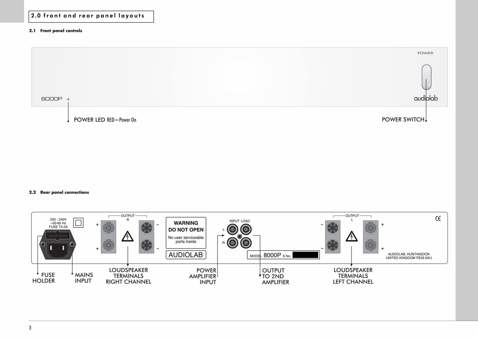
2.1 Front panel controls ..................................................................................3
2.2 Rear panel connections .............................................................................3
3.0 Pages 4 and 5 DELETED
4.0 functional tests
4.1 Test equipment required ............................................................................6
4.2 Functional test procedure ...........................................................................7
5.0 performance tests
5.1 Test equipment required ..........................................................................12
5.2 Performance test procedure .....................................................................13
6.0 test points
6.1 Functional and performance test points .....................................................17
7.0 circuit schematics
7.1 Master schematic diagram (SCH279M-01-06.................... .......................18
7.2 Power amplifier left channel schematic (SCH27901-03-07) .........................19
7.3 Power amplifier right channel schematic (SCH27901-02-07) .......................20
7.4 Power supplies protect and mute schematic (SCH27901-01-03) ..................21
8.0 printed circuit board layout
8.1 Printed circuit board layout (top view) .......................................................22
8.2 Printed circuit board layout (bottom view) ..................................................23
9.0 technical data
9.1 8000P Technical specifications ................................................................24
9.2 International standards ............................................................................25

1
1.0 safety and servicing notes
1.1 Safety precautions
1. This unit is Class II, which means that it is not connected to the protective earth system.
All live voltages are insulated from the case by double insulation.
2. Do not attempt to service unless qualified to do so.
3. Disconnect unit from AC power supply before removing cover.
4. Components marked with the symbol on the circuit schematic are safety critical
and must only be replaced with an identical component, or an alternative approved by
the manufacturer.
5. Switch unit off, and disconnect from supply before making and breaking any
connections.
6. Do not adjust any controls unless instructed to do so in this manual.
1.2 Electrostatic discharge precautions
Electrostatic discharge (ESD) is due to charges produced by insulating materials rubbing together.
Humans collect electrostatic charge through normal activities when clothes rub together and when
walking on carpet. This charge may be discharged suddenly when you touch a conductor. If the
conductor is connected to a sensitive electronic circuit, you may damage the components. It is also
possible to reduce the life of components without causing any obvious damage.
To prevent ESD damage, it is necessary to follow these guidelines.
1. Prepare work area. Place an ESD protective mat on the bench, strapped to the
protective earth circuit.
2. Prepare yourself. Put on an ESD protective wrist band, strapped to the protective earth
circuit, or to the ESD protective mat.
3. Keep all PCBs removed from unit in ESD protective bags.
4. Keep all replacement electronic components, PCBs and stock items in ESD protective
bags or boxes.
5. Be particularly careful with components marked with the following symbol:
1.3 Soldering
How to de-solder components
Components should be removed, wherever possible, using a de-soldering tool. Be careful not to
damage tracks and pads by applying too much pressure.
How to make good solder joints
1. Ensure surfaces are clean.
2. Keep soldering iron clean and wetted with solder. Use an appropriate bit. Do not leave
soldering iron on when not in use.
2
1.0 safety and servicing notes
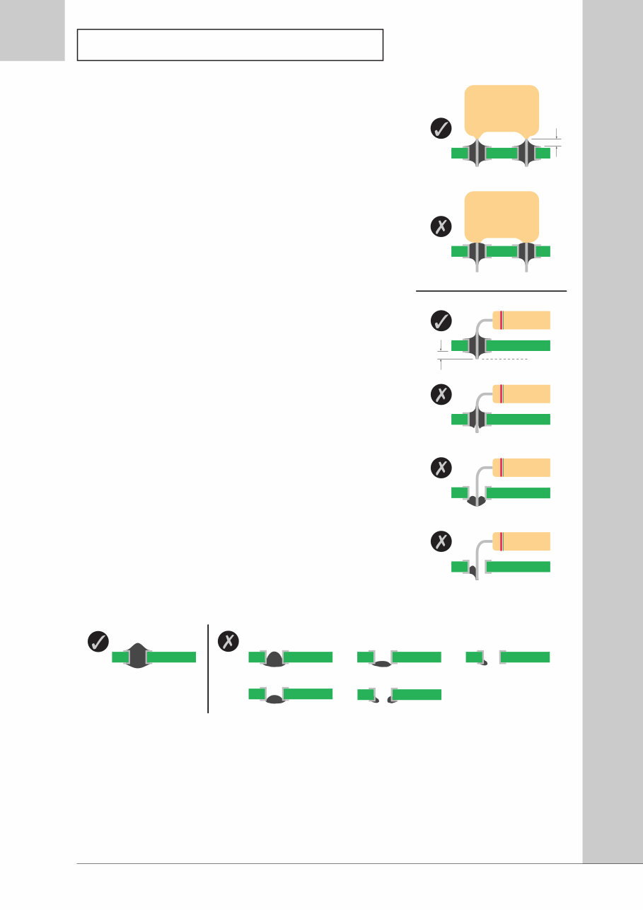
3. Apply soldering iron to both component lead and pad
before applying solder. Make sure that the soldering
iron is applied long enough for the solder to wet
properly, but do not apply for too long or component
damage may occur.
4. Allow a small gap between component body and
pad. Solder must not reach the base of the
component.
How to detect acceptable joints
1. Solder joints should have from a shiny to satin lustre
and a generally smooth appearance.
2. Solder should have wetted both the component lead
and pad.
3. There should be a concave meniscus between the
objects being soldered. The angle of solder to pad
should be less than 90° unless the solder joint extends
over the edge of the pad.
4. Solder should fill the component pad and wet
component lead around the full circumference (360°).
How to detect unacceptable joints
1. Poor wetting produces a bead of solder. The fillet will
be convex instead of concave, and there will not be a
feather edge.
2. On double-sided PCBs, solder should wet all round
plated-through hole, on both sides of the PCB.
Cleaning up after soldering
1. Flux is very corrosive. Remove with IPA (propan-2-ol) before completing the job.
2. Remove any solder balls and splashes from the unit.
3. Check all new solder joints and ensure all PCBs are clean before replacing covers.
4. After replacing covers, clean the case and any display windows with a damp cloth. Do
not use any organic solvents. If scratched, replace display windows.
Trim Line
6
4.0 functional tests
These notes are provided to assist you in servicing the amplifier. The circuit schematics are marked
with typical voltage levels, which may assist in defining the cause of any problem.
4.1 Test equipment required
Equipment
Digital Multimeter
Dual Tracking DC Power
Supply
Various Leads
Specification
Accuracy better than 0.5% in V and mV ranges
Output: ±32 V DC 2 A
Positive terminal of negative supply must be connected to
negative terminal of the positive supply unless internally linked
V mA V mA
-ve +ve
Select Tracking
0 V
+32 V
-32 V
Black = -ve
Red = +ve
Green = 0 V
-ve +ve
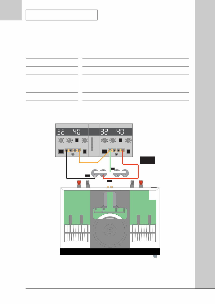
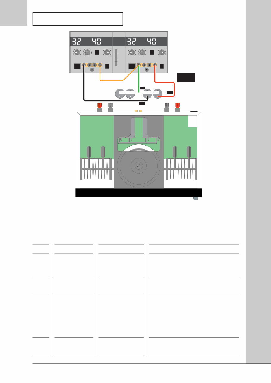
Figure 4.1 - Functional test set-up for left channel
7
4.0 functional tests
V mA V mA
-ve +ve
Select Tracking
0 V
+32 V
-32 V
Black = -ve
Red = +ve
Green = 0 V
-ve +ve
Figure 4.2 - Functional test set-up for right channel
No
4.2.1.
4.2.2.
4.2.3.
4.2.4.
Action
Disconnect all
cables from
amplifier
Check voltage
setting
Check fuse type
Check fuse
resistance
Test Equipment
Multimeter set
to W
Details
Read ratings label on rear of amplifier.
Open fuse holder in power socket on rear
panel.
Rated supply Fuse Type
230 V AC T4.0A L250V
115 V AC T5.0A 125V
100 V AC T6.3A 125V
Fuse and spare fuse should be low
resistance.
4.2 Functional test procedure
For test point (TP) references, see section 6.0 Test Points.

8
4.0 functional tests
4.2 Functional test procedure
For test point (TP) references, see section 6.0 Test Points.
No
4.2.5.
4.2.6.
4.2.7.
4.2.8.
4.2.9.
4.2.10.
4.2.11.
Action
Set up power
supply
Remove cover
Connect
supplies to left
channel as
shown in
Figure 4.1
Apply DC
voltage to
amplifier left
channel
Measure left
channel supply
rails
Measure
amplifier left
channel offset
Measure offset
of left channel
protection
circuit
Test Equipment
Dual tracking DC
power supply
Dual tracking DC
power supply
Dual tracking DC
power supply
Multimeter set to
V DC
Multimeter set to
mV DC
Multimeter set to
mV DC
Details
Set output voltage to ±32 V, current
limited to 500 mA.
With supplies off, connect
• positive output of supply to positive
terminal of positive rail capacitor
• negative output of supply to negative
terminal of negative rail capacitor
• common (0 V) output of supply to
common connection between two
capacitors
CAUTION:
Do not connect with the wrong polarity.
Check output of supplies is ±32 V and
switch output on.
Current output of each supply (+ve
and -ve) should be <100 mA. If higher,
turn RV101 (TP 9) and RV201 (TP 10)
fully anticlockwise.
Continue with test procedure if current
output of each supply is 40 mA ±5 mA.
If not, switch off and investigate.
Measure voltage across D110 (TP 1+
and TP 1-) and D111 (TP 2+ and TP 2-) .
Voltage should be 32 V ±0.25 V.
Connect negative probe to 0 V (TP 0).
Connect positive probe to R149 (TP 5) .
Voltage should be <5 mV.
Connect positive probe to junction of
Q105 and R158 (TP 7).
Voltage should be <5 mV.

9
4.0 functional tests
No
4.2.12.
4.2.13.
4.2.14.
4.2.15.
4.2.16.
4.2.17.
4.2.18.
Action
Connect
supplies to
right channel
as shown in
Figure 4.2
Apply DC
voltage to
amplifier right
channel
Measure right
channel supply
rails
Measure
amplifier right
channel offset
Measure offset
of right
channel
protection
circuit
Disconnect DC
power supplies
Fix any faults
Test Equipment
Dual tracking DC
power supply
Dual tracking DC
power supply
Multimeter set to
V DC
Multimeter set to
mV DC
Multimeter set to
mV DC
Details
With supplies off, connect
• positive output of supply to positive
terminal of positive rail capacitor
• negative output of supply to negative
terminal of negative rail capacitor
• common (0 V) output of supply to
common connection between two
capacitors
CAUTION:
Do not connect with the wrong polarity.
Check output of supplies is ±32 V and
switch output on.
Current output of each supply (+ve
and -ve) should be <100 mA. If higher,
turn RV101 (TP 9) and RV201 (TP 10)
fully anticlockwise.
Continue with test procedure if current
output of each supply is 40 mA ±5 mA.
If not, switch off and investigate.
Measure voltage across D210 (TP 3+
and TP 3-) and D211 (TP 4+ and TP 4-) .
Voltage should be 32 V ±0.25 V.
Connect negative probe to 0 V (TP 0).
Connect positive probe to R249 (TP 6) .
Voltage should be <5 mV.
Connect positive probe to junction of
Q205 and R258 (TP 8).
Voltage should be <5 mV.
If any faults have been detected, repair
and return to the beginning of this test
procedure.
4.2 Functional test procedure
For test point (TP) references, see section 6.0 Test Points.
You're Reading a Preview
What's Included?
Fast Download Speeds
Online & Offline Access
Access PDF Contents & Bookmarks
Full Search Facility
Print one or all pages of your manual
$36.99
Audiolab 8000AV Original Service Manual in
Viewed 32 Times Today

What's Included?
Fast Download Speeds
Online & Offline Access
Access PDF Contents & Bookmarks
Full Search Facility
Print one or all pages of your manual
$36.99

Secure transaction
What's Included?
Fast Download Speeds
Online & Offline Access
Access PDF Contents & Bookmarks
Full Search Facility
Print one or all pages of your manual
Description
The Audiolab 8000-AV Service Manual is a comprehensive resource for car repair, offering technical diagnostic procedures, disassembly and installation procedures, and wiring diagrams. It contains numerous illustrations and diagrams, making it useful for both professional mechanics and DIY enthusiasts. This manual is available in a format suitable for Windows XP, Vista, 7, 8, and Mac, ensuring compatibility with a wide range of systems. Whether you need to print specific pages or the entire manual, this resource provides the most complete service-workshop manual available. Written by the manufacturer and used by dealership mechanics, it guarantees 100% satisfaction and is virus-free.


