

SERVICE MANUAL
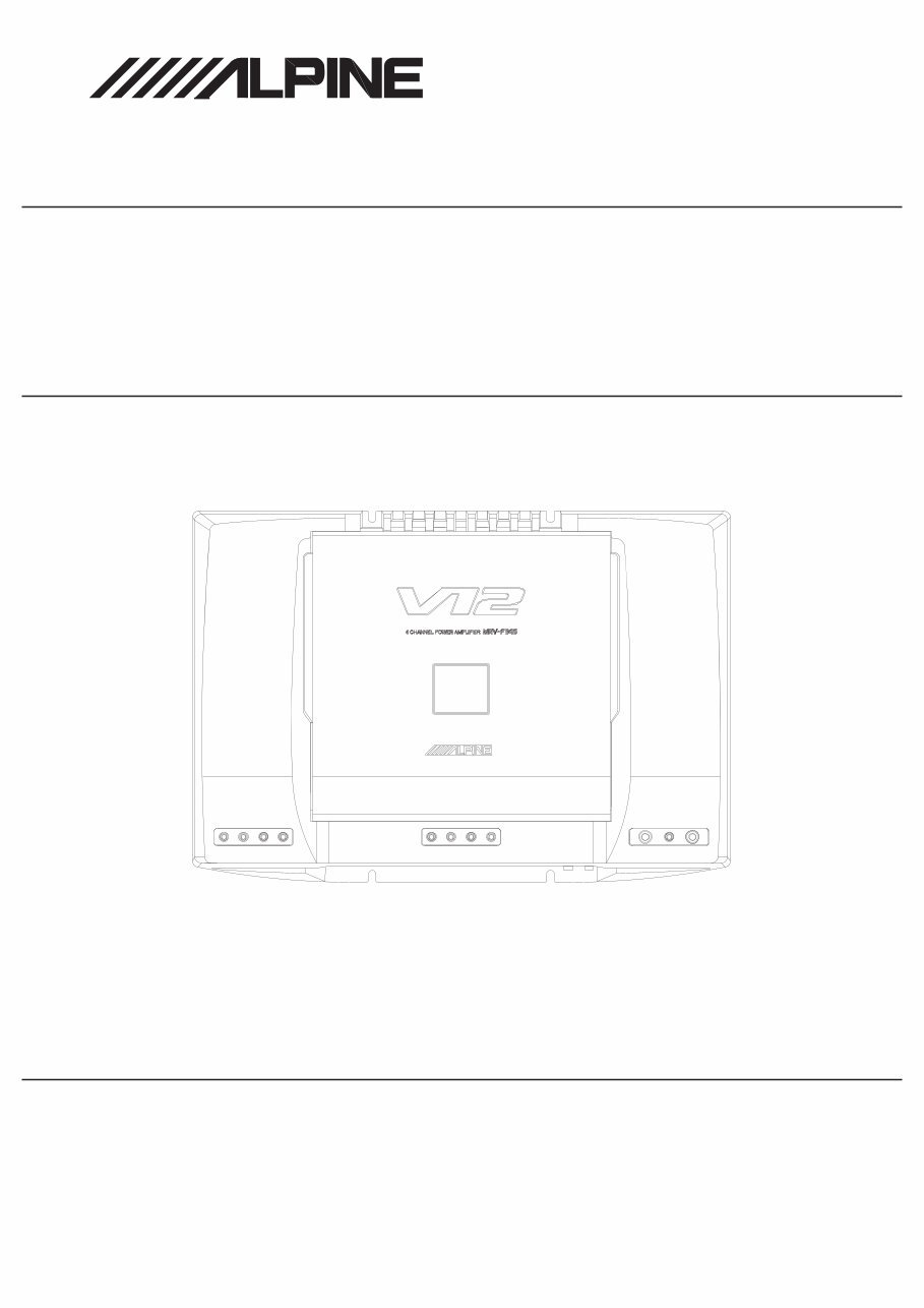
4 CHANNEL POWER AMPLIFIER
1 / 05-A
68E37844S01
MRV-F345
"Schematic Diagram cannot use a reference function"
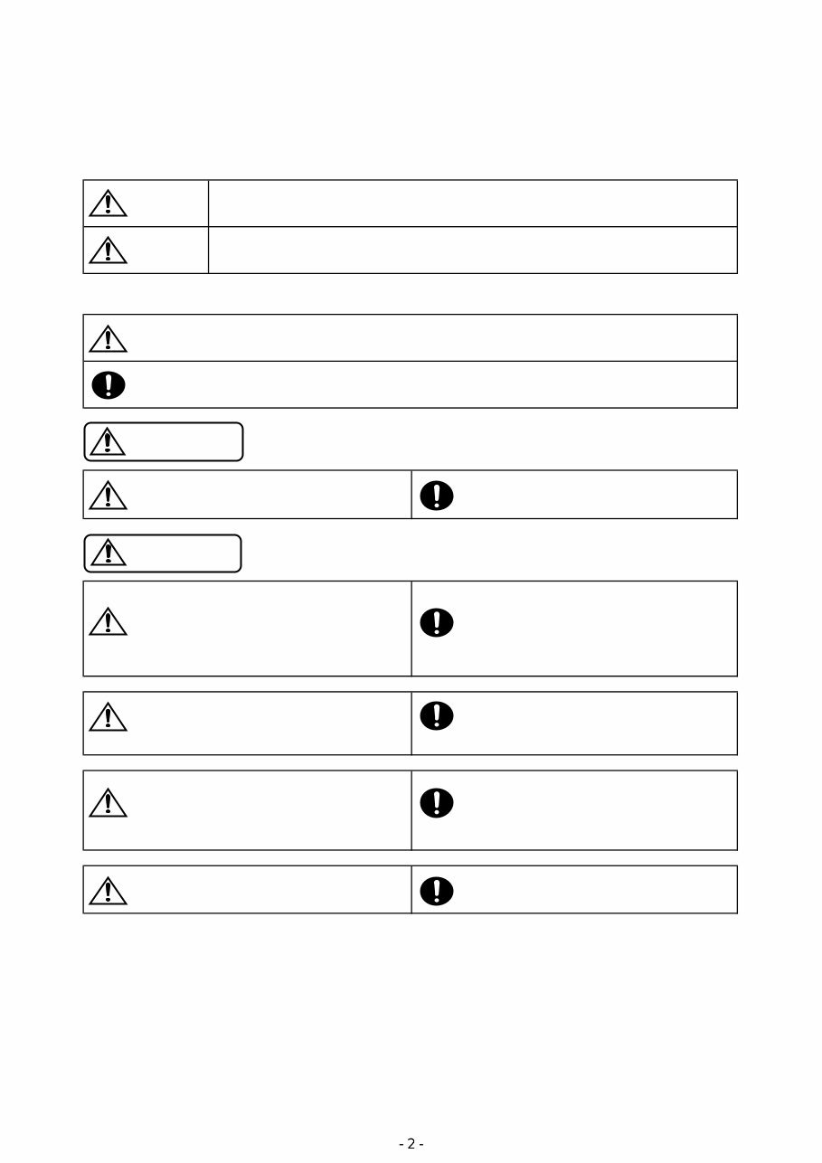
<Cautions for Safe Repair Work>
The following cautions will prevent accidents in the workplace and will ensure safe products.
*The symbols indicate caution is needed to prevent injuries and damage to property.
The symbols and their meanings follow.
*The following symbols indicate two levels of cautions.
When you see this symbol, you have to be very careful.
When you see this symbol, you have to follow the instructions there.
Do not look squarely into the laser light Fuse Caution
coming from the pickup. Always use a designated fuse.
You may loose you sight. Use of an incorrect fuse may result in a fire.
Do not allow wiring to be caught in the Battery Caution
screw/chassis. Use the designated battery.
If wiring is caught in the screw/chassis, it may Confirm the correct polarity and seat of the
cause a short circuit, resulting in a fire. battery.
An incorrect battery or an improperly connected
or seated battery may result in a fire.
High Temperature Caution Designated Parts Caution
Touching the heat sink may cause severe burns. Look up the part list and ensure that only
designated parts are used to prevent problems or
accidents.
Reverse Power Supply Connections or Wiring Caution
Misconnections Caution Ensure that the wiring is correct when rewiring to
Reverse power supply connections or prevent problems with ignition/breakdown.
misconnections may cause ignition problems and
smoke may result.
Soldering Caution Wear Gloves
Hot solder from solder splash may cause severe Wear gloves to prevent electrical shocks or injury
burns. from the end face of the metal.
If you ignore this symbol and handle the product incorrectly or unsafely,
injury or only material damage may result.
If you ignore this symbol and handle the product incorrectly or unsafely,
serious injury or death may result.
Warning
Caution
Warning
Caution

MRV-F345
Contents
Packing Assembly Parts List
4
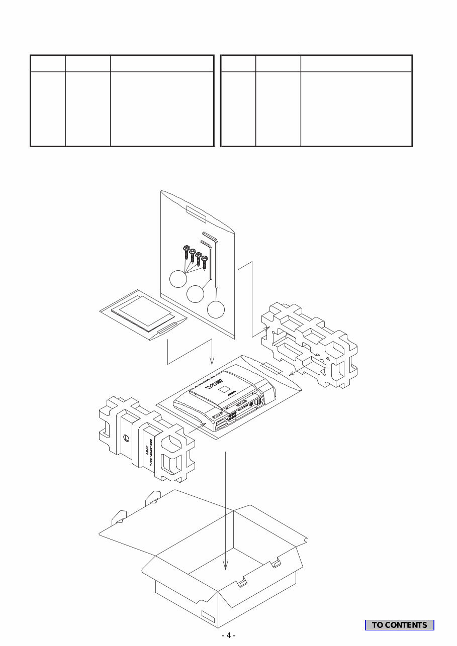
Packing Method View
4
Specifications
5
Extension Cable
6
Block Diagram
7
Parts Layout on P.W.Boards and Wiring Diagram
8 to 10
Schematic Diagram
11 to 17
Terminal Voltage of IC/TR
18 to 21
Description of IC Terminal
22
Exploded View (Cabinet)
23
NOTE : Due to continuing product improvement, specifications and designs are subject to
change without notice.
MRV-F345
Packing Assembly Parts List
Part No. Part No.
101-1 03E38301S01 SCR,M4X20 BLK
101-2 03E38302S01 WRENCH,M2.5
101-3 03E38303S01 WRENCH,M4
#1 102 68-02278Z39 OWNER'S MANUAL
$1 102 68-02278Z40 OWNER'S MANUAL
$1 102 68-02278Z41 OWNER'S MANUAL
NOTE:#1:For North American Model Only,$1:For General Foreign Model Only,Others:Common.
Packing Method View
Description
No. No.
Symbol Symbol Description
101 -1
101 -2
101 -3 MRV-F345

Specifications
Power Output ............................................................................. 4ohm x 4ch, 0.3% T.H.D.+N, 20Hz to 20kHz : 75W
ch 3/4 : 2ohm & 2ohm, 0.8% T.H.D.+N, 20Hz to 20kHz : 150W
ch 3/4 : 4ohm-BTL, 0.8% T.H.D.+N, 20Hz to 20kHz : 300W
T.H.D. ............................................................................................. 4ohm x 4ch, 75W Power, 20Hz to 20kHz : 0.08%
ch 3/4 : 2ohm & 2ohm, 150W Power, 20Hz to 20kHz : 0.8%
ch 3/4 : 4ohm-BTL, 300W Power, 20Hz to 20kHz : 0.8%
Input Sensitivity (RCA Voltage) ................................. Input Gain 0.2V position, 17.4V sine wave output : 0.25±0.5V
Input Gain 4.0V position, 15.0V sine wave output : 4.0±0.5V
Pre Out Level (Input 0.5Vrms) ...................................................................................................................... 0.5±0.1V
Frequency Response (1kHz 0dB, 1W) .............................................................................................. 20Hz : -1 to 0dB
50kHz : -1 to 0dB
Channel Separation (Input shorted, 1kHz, 1W) .................................................................................................. 55dB
S/N Ratio (Input shorted, Signal : 75W) ............................................................................................................. 90dB
Remote Voltage (ON/OFF) ........................................................................................................................... 5 to 7.5V
Current Drain ...................................................................................... Remote (Remote Voltage 14.4V) : 1.3±0.3mA
No Signal : 0.7 to 2.5A
75W x 4 Output (4ohm x 4ch, 1kHz) : 43±4A
Back up (15 seconds later) : 5mA
Fuse Requirement .................................................................................................. 30A (Peak) x 2 (For Battery Line)
Power Source ......................................................................................................................... DC14.4V (10.5 to 16V)
Dimensions (W x H x D) ............................................................................................................. 330 x 61 x 227.8mm
Weight ................................................................................................................................................................ 3.5kg
NOTE : Due to Continuing product improvement, specifications and designs are subject to change without notice.
MRV-F345
MRV-F345
Extension Cable
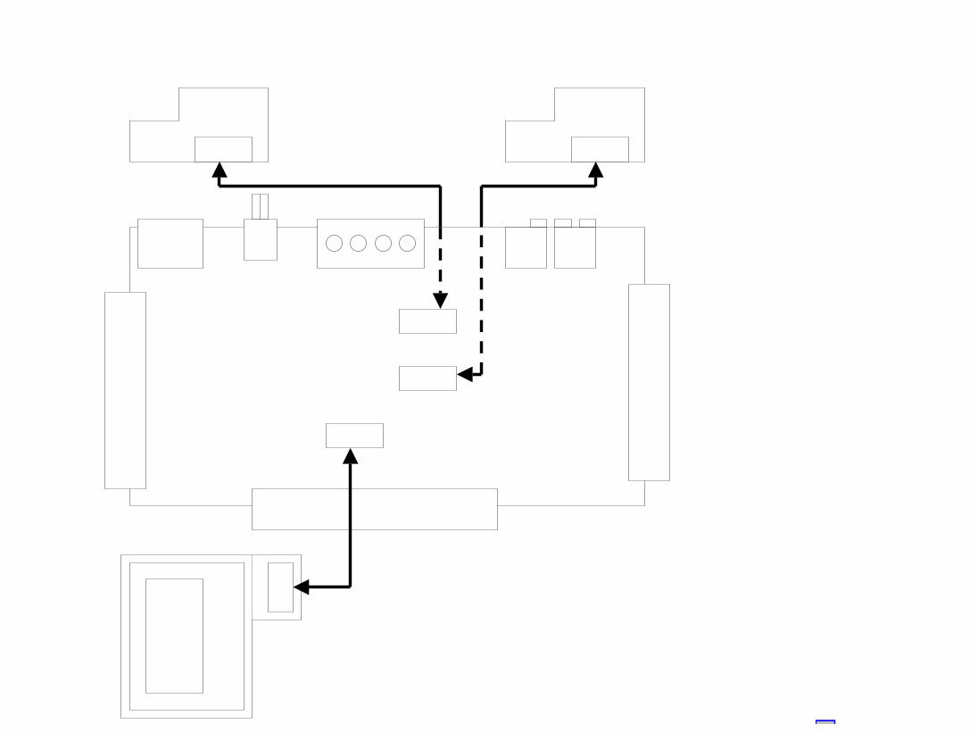
*Always connect the Extension Cable when making checks of voltage and repair.
CN702
CN501
CN502
MAIN P.W.Board
CN520 CN540
VR1 P.W.Board VR2 P.W.Board
(2) (1)
(3) (1) No Extension *
(2) No Extension *
(3) 01E37824S01
CN602
* It is possible to use by
existing cable in product.
LCD P.W.Board
Block Diagram
MRV-F345
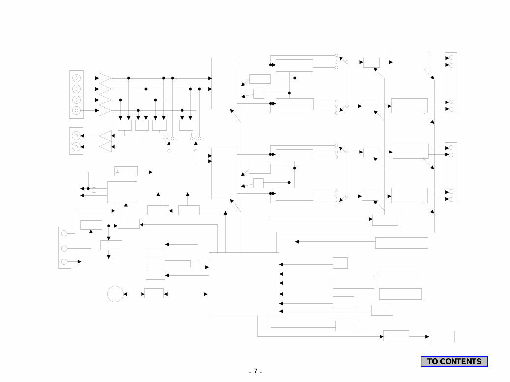
RCA INPUT
4CH
MIX MIX MIX MIX
2CH
LINE OUT
ISO. AMP
BUFFER
VOLUME IC
VARIABLE FILTER
VARIABLE FILTER
FLAT
FLAT
LPF
LPF
HPF
HPF
ch1
ch2
ch3
ch4
INPUT SELECTOR
FILTER
X20
FREQ VR
MUTE
MUTE ch2 POWER AMP
ch1 POWER AMP
SPEAKER
TERMINAL
ch1
ch2
VOLUME IC
VARIABLE FILTER
VARIABLE FILTER
FLAT
FLAT
LPF
LPF
HPF
HPF
FILTER
X20
FREQ VR
MUTE
MUTE ch4 POWER AMP
ch3 POWER AMP
SPEAKER
TERMINAL
ch3
ch4
VOL_CONTROLL
MUTE DRIVE
MUTE
DC-OFFSET , OUTPUT-CURRENT-LIMIT
CE1 , CE2 , CL , DI
FREQ , X20
OUTPUT THERMAL DETECT
OUT_THRM
9V REG 5V REG
to VOLUME IC to LCD
POW P1
LM20
AD THRM DET
THERMAL DETECT 2
AD THRM
VOLTAGE DETECT
AD VOLT
VOLTAGE DETECT
AD VOLT
BD5243G
B DET
BD5242G
RESET
BR24L01A
I2C (SDA SCL)
FAN DRIVE
FAN1 , FAN2
uPC494
POW P2
38V
to AMP
15V REG to OP-AMP
LCD
CE,DI,CLK,INH
KEY
AD-KEY
LED
LED
BUFFER
DIN,DOUT,CLK
AMPLINK
DIN 6P
uCOM
5V REG
REM-ON
to uCOM
POWER
TERMINAL
+B
REM
GND
DC/DC Conv.
DC FAN
40V
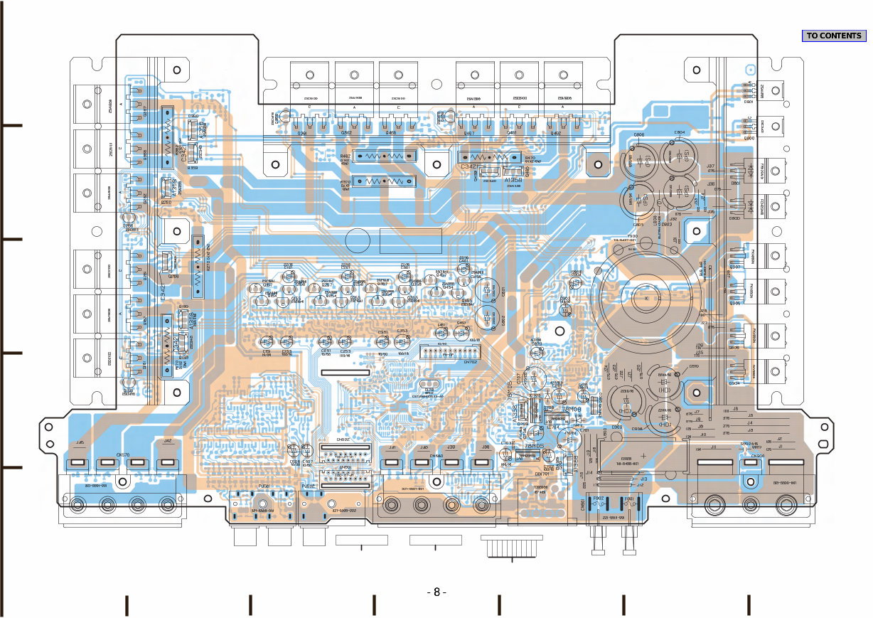
Orange Color Pattern:Component Side Pattern
Blue Color Pattern:Foil Side Pattern
MRV-F345 Parts Layout on P.W.Boards and Wiring Diagram(1/3)
MAIN P.W.Board (Component Side View)
11 1
1 17
17
16 2
2
1
B E B E B E B E B E B E
B E
1
1
1 1 1 1
1 1 1
4 1
5 1
3 4 2 1
1 3
3 1
3 1
1
B
G
D
G
D
G
D
G
D
E
B
E
B
E B E B E B E B E B E B
E B
E B
E B E B
E B E B
E B E B
E B E B
E B E B
E B
E B
E B E B
E B
E
3
2 4
6
3
4
16
From LCD P.W.Board (CN602)
BLK
WHT(1)
WHT(5)
WHT(4)
WHT(2)
WHT(6)
WHT(9)
WHT(7)
WHT(8)
WHT(10)
WHT(3)
To CN702
1 11
17 1
To CN501
2 16
To VR2 P.W.Board (CN540) To VR1 P.W.Board (CN520)
16 2
To CN502
1 17
1
2
3
4
5
A F G E D C B
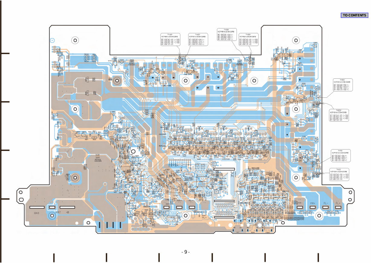
Orange Color Pattern:Component Side Pattern
Blue Color Pattern:Foil Side Pattern
MRV-F345 Parts Layout on P.W.Boards and Wiring Diagram(2/3)
MAIN P.W.Board (Foil Side View)
B E
B E B
E
B
E
B
E
B
E
B
E
B
E
B E
B E
B E
B E
B E B E
B E
B E
B E
B
1
2
5
3
1
2
5
3
1
2
5
3
1
2
5
3
3
1
4
5
3
1
4
5
E
B
E
B
E
B
E
B
E
B
E
B
E
B E
B E
B E
B E
B E
B E
B
E
B
E
B
E
B
E
B E
1
2
3
4
5
A F G E D C B
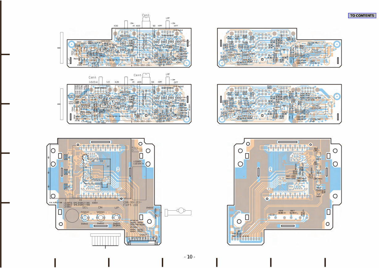
Orange Color Pattern:Component Side Pattern
Blue Color Pattern:Foil Side Pattern
VR1 P.W.Board
(Component Side View)
MRV-F345 Parts Layout on P.W.Boards and Wiring Diagram(3/3)
VR2 P.W.Board
(Component Side View)
LCD P.W.Board (Component Side View)
VR1 P.W.Board (Foil Side View)
VR2 P.W.Board (Foil Side View)
LCD P.W.Board (Foil Side View)
17 1
To MAIN P.W.Board (CN501)
To CN520 To CN540
To MAIN P.W.Board (CN502)
1 17
1 11
To CN602
WHT(3)
WHT(10)
WHT(8)
WHT(7)
WHT(9)
WHT(6)
WHT(2)
WHT(4)
WHT(5)
WHT(1)
BLK
To MAIN P.W.Board (CN702)
CN601
ASS'Y,WIRE 11P
2 1
To CN603
ASSY,FAN F4010BQ-12
FAN1
M
BLK RED
E
2
1
B
E B
E
32 17
1 16
32 17
1 16
B
1
2
3
4
5
A F G E D C B
CABLE,FLAT 17P
CN521
CABLE,FLAT 17P
CN541
You're Reading a Preview
What's Included?
 Lifetime Access
Fast Download Speeds
Online & Offline Access
Access PDF Contents & Bookmarks
Full Search Facility
Print one or all pages of your manual
$30.99
ALPINE MRV-F345 CAR POWER AMPLIFIER Service Manual
Viewed 11 Times Today

What's Included?
Lifetime Access
Fast Download Speeds
Online & Offline Access
Access PDF Contents & Bookmarks
Full Search Facility
Print one or all pages of your manual
$30.99

Secure transaction
What's Included?
Lifetime Access
Fast Download Speeds
Online & Offline Access
Access PDF Contents & Bookmarks
Full Search Facility
Print one or all pages of your manual
Description
The ALPINE MRV-F345 CAR POWER AMPLIFIER Service Manual is a comprehensive guide that includes the following:
- Packing Assembly Parts List
- Packing Method View
- Specifications
- Extension Cable
- Block Diagram
- Parts Layout on P.W.Boards and Wiring Diagram
- Schematic Diagram
- Terminal Voltage of IC/TR
- Description of IC Terminal
- Exploded View (Cabinet)
This manual, available in English, spans 39 pages and is compatible with both Windows and MAC platforms.


