Volvo L60E Wheel Loader Workshop Service Repair Manual
What's Included?
Lifetime Access
Fast Download Speeds
Offline Viewing
Access Contents & Bookmarks
Full Search Facility
Print one or all pages of your manual
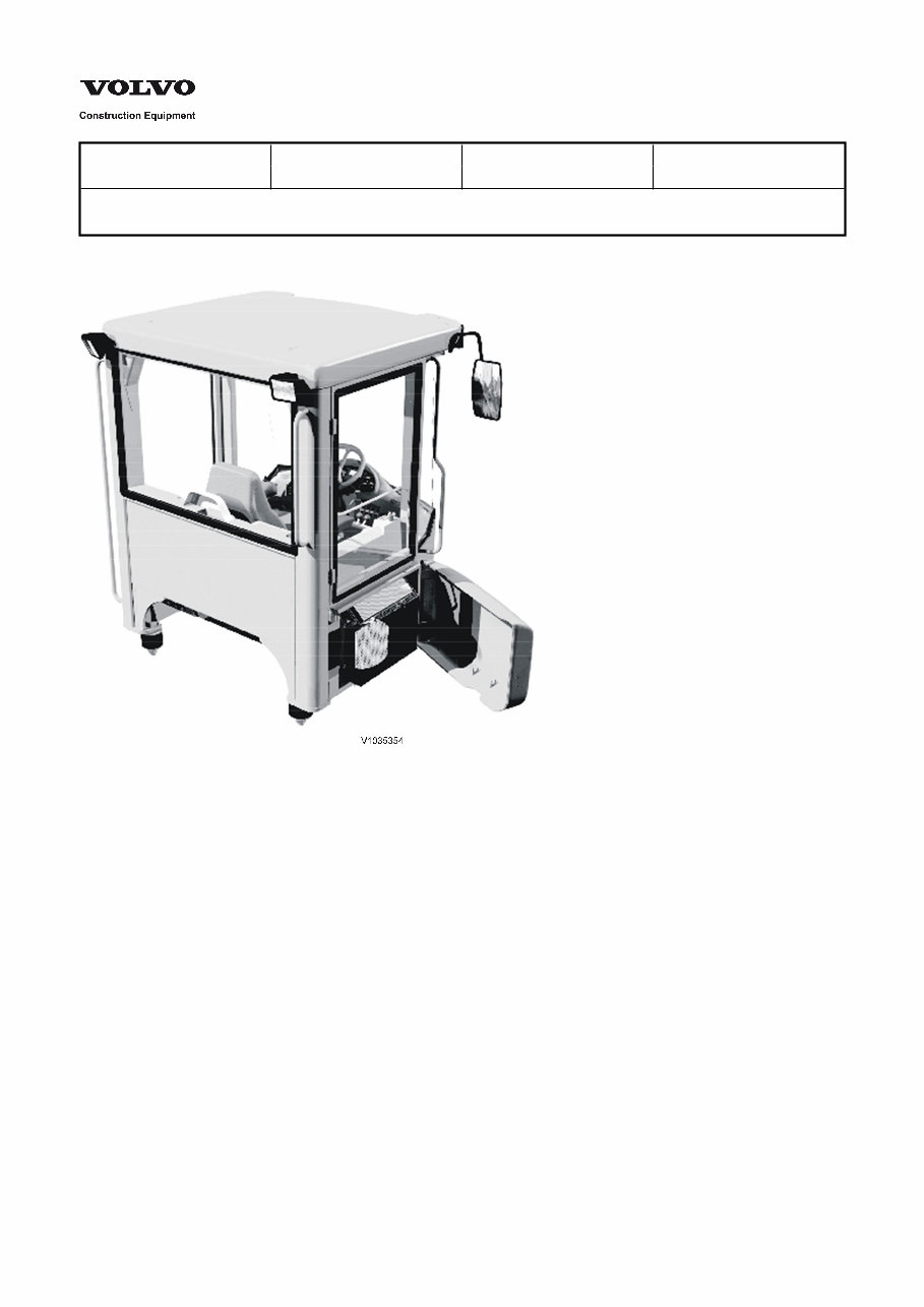
Service Information Document Title: Function Group: Information Type: Date: Cab, description 800 Service Information 2014/3/27 Profile: WLO, L60E [GB] Cab, description Figure 1 The cab is mounted to the frame via four vibration damping rubber pads. The rubber pads reduce noise and vibrations that otherwise would be transmitted to the cab. The cab consists of a frame that is designed to withstand compression in case the machine rolls over. This also applies to cabs without doors and windows (open rops). In addition to frame strength, the cab is adapted to the operator's need for good visibility. Not only visibility of the attachment, but also all around the machine. The inside of the cab is spacious and has several storage compartments. The instruments are located at the front and on the right side in the cab. An display unit provides continuous information about the different functions of the machine, for example, fuel consumption. For operator comfort, there is a wide range of seats available as well as an adjustable steering wheel that can be adjusted both in height and longitudinally. Instead of using the steering wheel, the operator can select lever steering (CDC). In this way, the operator steers the machine with the left hand and the attachment with the right hand. The air in the cab is filtered twice when drawn from outside and once when recirculated. The climate in the cab can be further improved with the aid of the optional accessories AC (Air Conditioning) or ATC (Automatic Temperature Control).
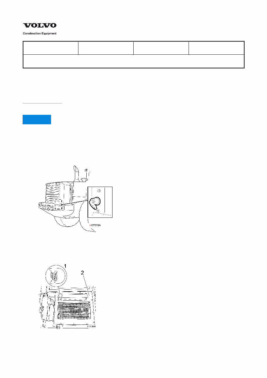
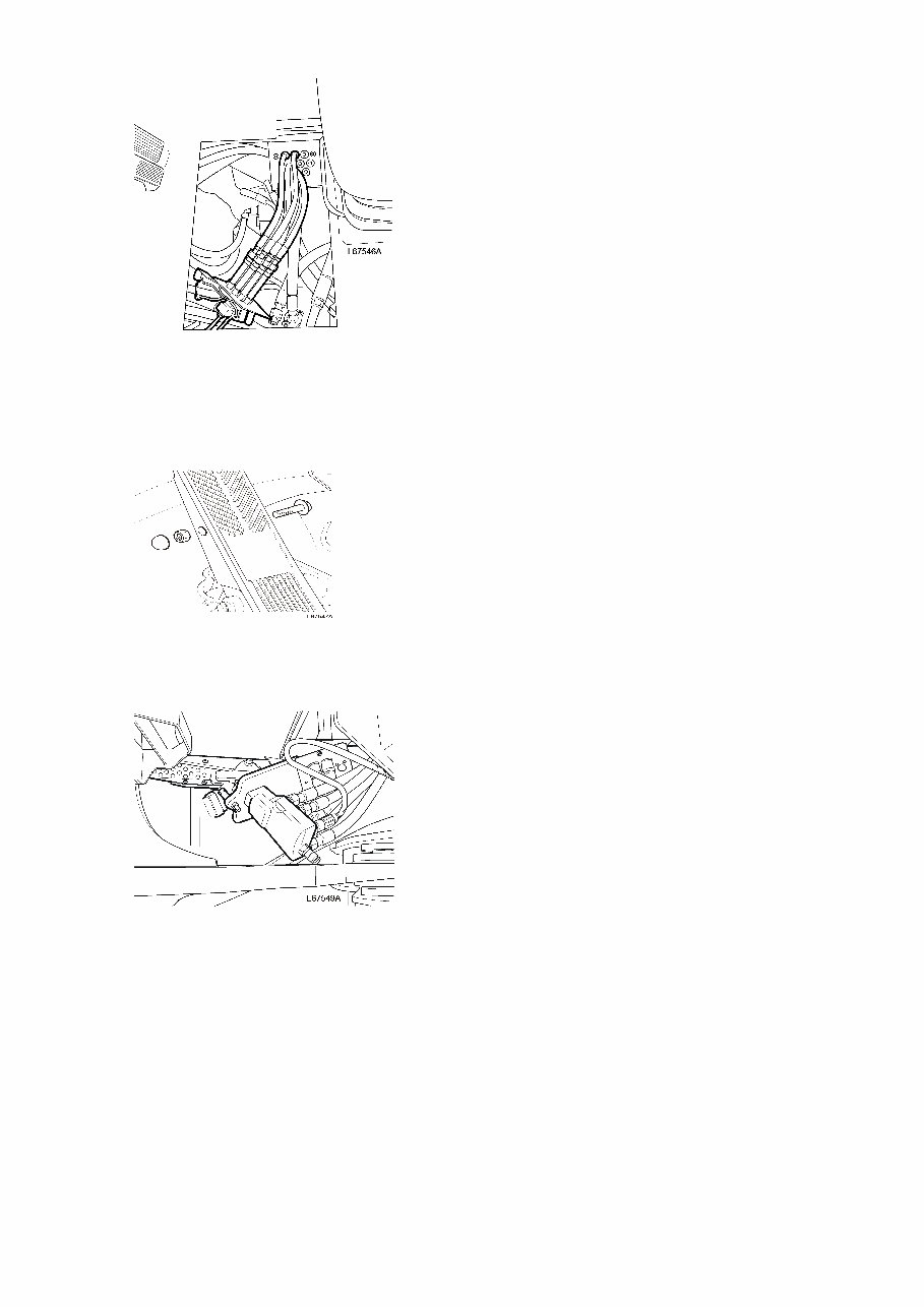
Service Information Document Title: Function Group: Information Type: Date: Cab, removing 810 Service Information 2014/3/27 Profile: WLO, L60E [GB] Cab, removing Op nbr 81001 Sling 4 m (13 ft), 4 pcs NOTICE When working on a machine equipped with air conditioning. Do not disconnect any hoses or connections on the air conditioning, thereby involuntary releasing refrigerant. Steps 4–6 apply to machines equipped with air conditioning. 1. Place the machine in service position. 2. Turn off the electric power with the battery disconnect switch. Figure 1 Battery disconnect switch, position (principle illustration) 3. Remove the filter cover together with the air filters. Remove the plate together with the recirculation damper. Figure 2
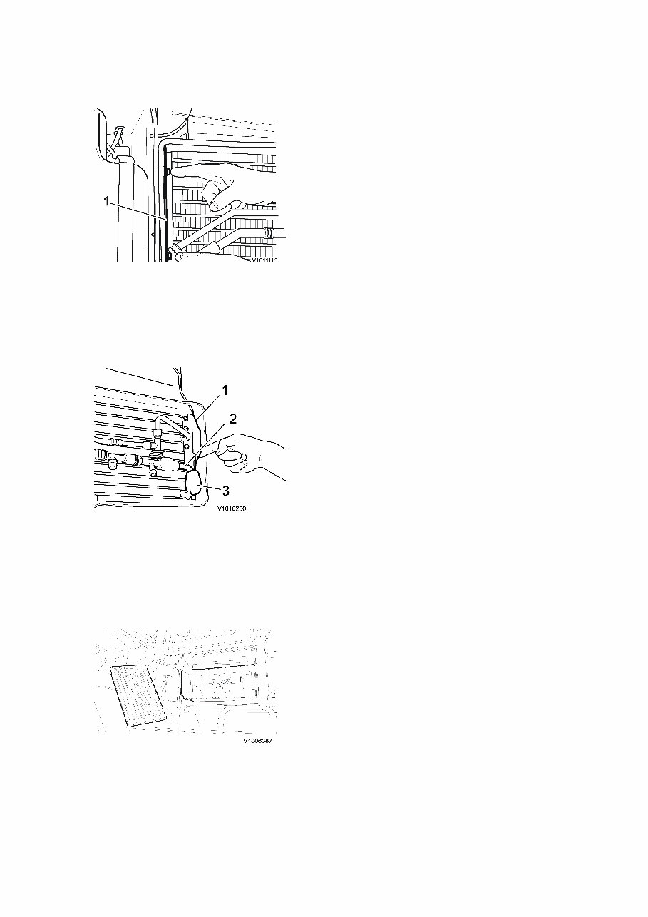
1. 2. Striker plate, recirculation damper Plate 4. Remove the support plate holding the evaporator. Figure 3 Support plate 1. Support plate 5. Remove the insulating compound. Carefully wind up and detach the capillary tube from the evaporator and filter cover. Figure 4 Capillary tube 1. 2. 3. Capillary tube Evaporator pipe Insulating compound 6. Carefully fold out the evaporator and suspend it to one side so that it is not damaged. Figure 5 Evaporator 7. Use a pair of hose pliers on the coolant hoses or drain off the coolant. Disconnect the coolant hoses from the cab heater. 8. Loosen the throttle pedal and spacer from the floor. Remove the floor mat.
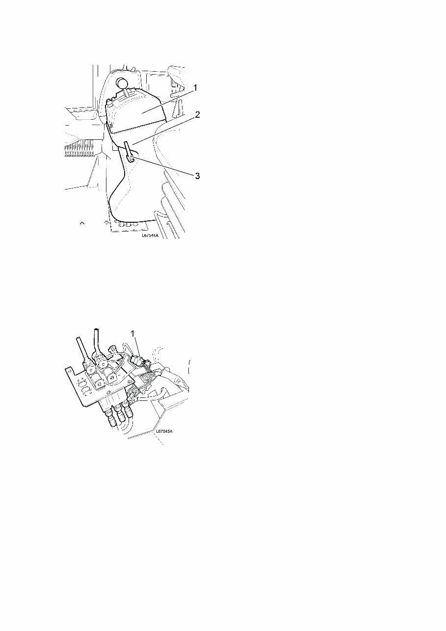
9. Remove the balls from the servo levers. Remove the cover from the servo levers. Remove the plastic cover on the side of the control lever carrier and the lever for adjusting the angle of the control lever carrier. Figure 6 1. 2. 3. Upper cover Side cover Lever for adjusting angle 10. Remove the servo valve from the control lever carrier. Unplug the connector on the servo valve. Figure 7 1. Connector 11. Remove the front floor plate. Lower the servo valve through the hole in the floor and put it in a protected location.
Figure 8 12. Remove the extra pedal for operating the foot brake. Figure 9 13. Remove the foot brake valve from the cab floor and place it on the frame. Figure 10 14. Remove the steering valve from the cab floor and place it on the frame.
Figure 11 1. Attaching bolts (4 pcs) 15. Detach the cable harness from the electrical distribution box. Remove the lead-through plate from the rear cab wall and pull out the cable harness through the hole. Figure 12 L60E - L180E 16. Remove the four cab attaching bolts and washers. Figure 13 Cab rubber pad (principle illustration) 1. 2. 3. 4. 5. Adjusting shim Thrust washer Vibration damper Thrust washer Washer
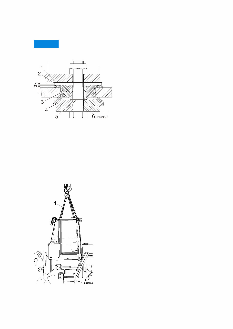
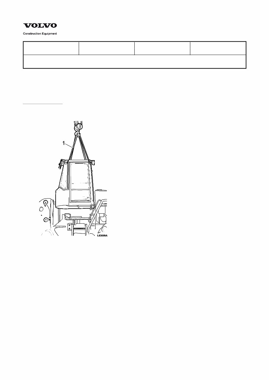
L220E 17. Remove the cab's four attaching bolts, the washers, the plate and any adjusting shims. NOTICE The shims must be put on the same cab mounting element from which they were removed in order not to change its characteristics. Figure 14 Cab rubber pad (principle illustration) 1. Adjusting shim, selected before rubber pad is in place, used to compensate for measurement deviations between the cab and cab mount 2. Washer 3. Mount 4. Plate 5. Adjusting shim, thickness approx. 1 mm (0.04 in) (only front cab member) 6. Washer A. Air gap 18. Connect the lifting device and sling as illustrated. Figure 15 1. Sling 4 m (13 ft), 4 pcs
19. Lift off the cab. Cab weight: approx. 800 kg (1764 lb) 20. Retain the washer from each cab rubber pad.
Service Information Document Title: Function Group: Information Type: Date: Cab, installing 810 Service Information 2014/3/27 Profile: WLO, L60E [GB] Cab, installing Op nbr 81002 Sling 4 m (13 ft), 4 pcs 1. Attach the lifting device. Figure 1 1. Sling 4 m (13 ft), 4 pcs L60E - L180E 2. Place the thrust washer (2) and adjusting shim on each cab rubber pad.
Figure 2 Cab rubber pad (principle illustration) 1. 2. 3. 4. 5. Adjusting shim Thrust washer Vibration damper Thrust washer Washer 3. Lift the cab into place. Cab's weight: approx. 800 kg (1764 lbs). Fit thrust washer (4) and washer together with each bolt. 4. Tighten the bolts. Tightening torque, rear mount–frame: 400-450 Nm (295-332 lbf ft) Tightening torque, front mount–frame: 400-450Nm (295-332 lbf ft) L220E 5. Place a washer (2) and any adjusting shims (1) on each cab member. Figure 3 Cab rubber pad (principle illustration) 1. Adjusting shim 2. Washer A. Air gap 3. Mount 4. Plate 5. Adjusting shim. Thickness approx. 1 mm (0.040 in) NOTICE The shims must be put on the same cab mounting element from which they were removed in order not to
The Volvo L60E Wheel Loader Workshop Service Repair Manual is a comprehensive guide designed for professional technicians and do-it-yourself mechanics alike. This complete official full factory service repair manual covers all styles and provides step-by-step instructions for repairing and maintaining the Volvo L60E Wheel Loader.
Featuring easy-to-read text sections, high-quality diagrams, and instructions, this manual equips both novice and experienced mechanics with the knowledge to efficiently complete any required job. It includes critical specifications, illustrations, maintenance procedures, disassembly and assembly instructions, and much more.
Whether you opt for a paper manual or the digital version, you'll have access to the same features. The digital manual offers the advantage of instant access without any waiting or shipping fees, allowing you to start repairs immediately. It is available in English and is compatible with all versions of Windows and Mac.
What sets this digital manual apart is its instant delivery upon purchase, eliminating the need for any additional software. It provides a hassle-free experience, ensuring you receive exactly what you paid for. In case of any issues, customer support is readily available to assist you.
This manual covers a wide range of topics including routine maintenance, care and safety, body and framework, engine, electrical system, power transmission, brake, steering, hydraulic system, and more, making it an invaluable resource for anyone working with the Volvo L60E Wheel Loader.
Recently Viewed
5,521,897Happy Clients
2,594,462eManuals
1,120,453Trusted Sellers
15Years in Business
Price:
Actual Price:
Volvo L60E Wheel Loader Workshop Service Repair Manual