VOLVO L50E Wheel Loader Full Service Repair Manual
What's Included?
Lifetime Access
Fast Download Speeds
Offline Viewing
Access Contents & Bookmarks
Full Search Facility
Print one or all pages of your manual
Service Information Document Title: Function Group: Information Type: Date: Cab, removing 810 Service Information 2014/3/27 Profile: WLO, L50E [GB] Cab, removing Op nbr 81001 Sling 4 metres (13 ft), 4 pcs NOTICE When working on a machine equipped with air conditioning. Do not disconnect any hoses or connections on the air conditioning, thereby involuntary releasing refrigerant. 1. Applies to machine with air conditioning. Detach the evaporator from the cab and lay it in a protected position on the steps. 2. Use a pairs of hose pliers on the coolant hoses or drain off the coolant. Then disconnect the coolant hoses from the cab heater unit. 3. Remove the casing over the control levers. 4. Remove the plastic casing on the side of the control lever carrier and the lever for angle adjustment of the control lever carrier. 5. Remove the servo valve from the control lever carrier. 6. Detach the electromagnets from the servo valve. 7. Remove the floor mat. 8. Remove the centre floor plate. 9. Lower the servo valve down through the hole in the floor. 10. Detach the foot brake valve and the steering valve from the cab floor and place them on the frame. 11. Disconnect the control cable from the accelerator pedal. 12. Disconnect the connectors on the cable harnesses from the electrical distribution box and remove the plate with the cable lead-throughs from the cab wall. Pull the cable harnesses out of the cab through the opening in the cab wall. NOTICE The shims must be put on the same cab mounting element from which they were removed in order not to change its characteristics. 13. Remove the four attaching bolts, washer, plate and any shims.
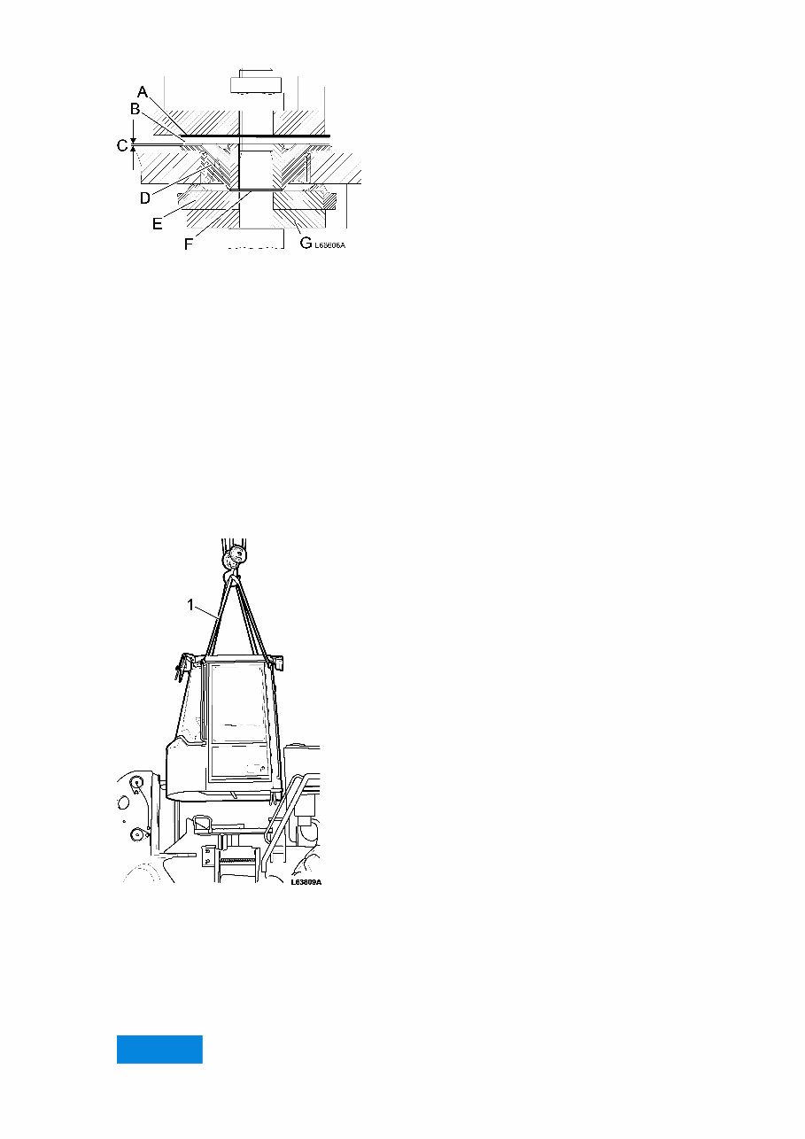
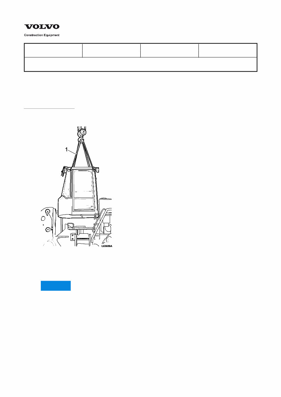
Figure 1 Cab element (principle diagram) A Shim B Washer C Air slot D Attachment E Plate F Shim, approx. 1 mm (0.04 in) thick (front cab element only) G Washer NOTE! With effect from machine number 1110– plate E has a vulcanised-on rubber element. 14. Connect a lifting device and slings. Figure 2 1. Sling 4 m (13 ft), 4 pcs. 15. Lift off the cab. Cab weight, approx. 800 kg (1764 lb). 16. Take care of washer and any shims from each cab element. NOTICE
The shims must be put on the same cab mounting element from which they were removed in order not to change its characteristics.
Service Information Document Title: Function Group: Information Type: Date: Cab, installing 810 Service Information 2014/3/27 Profile: WLO, L50E [GB] Cab, installing Op nbr 81002 Sling 4 metres (13 ft), 4 pcs 1. Connect a lifting device and slings. Figure 1 1. Sling 4 m (13 ft), 4 pcs NOTICE The shims must be put on the same cab mounting element from which they were removed in order not to change its characteristics. 2. Position a washer and any shim on each cab element.
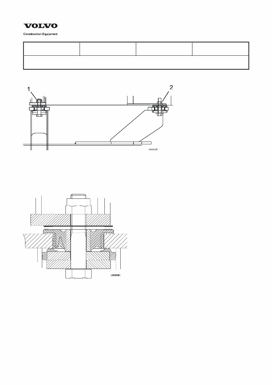
Figure 2 Cab element (principle diagram) A Shim B Washer C Air slot D Attachment E Plate F Shim, approx. 1 mm (0.04 in) thick G Washer 3. Lift the cab into position. Install plate E, washer G and any shim F on each bolt. 4. Tighten down the bolts. Tightening torque, rear bracket–frame, 580 Nm (428 lbf ft). Tightening torque, front bracket–frame, 400 Nm (399 lbf ft). 5. Check air slot C on each cab element. The air slot should be visible at some place, all or part of the way round. 6. If no air slot is visible, remove the bolt and fit an extra shim. Then tighten the bolt to the correct torque. A maximum of two shims may be installed on each cab element. 7. Remove the lifting device 8. Connect the coolant hoses to the cab heater unit. 9. Reposition the evaporator in climate control unit 10. Install the servo valve on the control lever carrier and secure the electro magnets. 11. Connect all cable harnesses to the electrical distribution box according to markings. 12. Secure the foot brake valve and the steering valve to the cab floor. 13. Connect the control cable to the accelerator pedal. 14. Install the centre floor plate. 15. Install the floor mat.
Service Information Document Title: Function Group: Information Type: Date: Cab suspension, description 818 Service Information 2014/3/27 Profile: WLO, L50E [GB] Cab suspension, description Figure 1 Cab suspension 1. 2. Rear cab element Front cab element Figure 2 Rear cab element
Figure 3 Front cab element
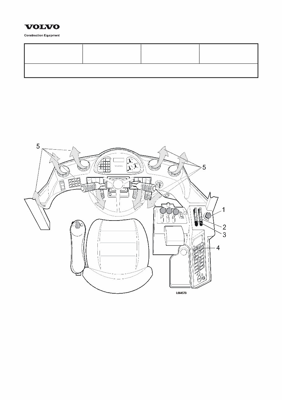
Service Information Document Title: Function Group: Information Type: Date: Climate control system, description 870 Service Information 2014/3/27 Profile: WLO, L50E [GB] Climate control system, description The machine is equipped with a climate control system where the fan can maintain a permanent excess pressure in the cab to keep out pollutants. All air will also be filtered, i.e. even recirculated air. As standard, the cab is equipped with a heater unit, but air conditioning (AC) is also available as optional equipment. All controls for the climate control system are positioned by the right instrument panel. The fan has four speeds and is controlled by rotary switch 1. The temperature is controlled with a sliding control 3 which, via a control cable, actuates a valve for controlling the flow of coolant through the heater unit. Sliding control 2 controls the amount of air which is to be recirculated. Button 4 is used for starting the air conditioning. Figure 1 1. 2. 3. 4. 5. Fan speed control Recirculation control Temperature control Air conditioning switch Ventilation nozzles The air is distributed through 10 ventilation nozzles that are individually adjustable and can be closed if needed. The air in the cab is discharged through a one-way outlet fitted with slats and placed in the cab door. In order to open the slats a certain degree of excess pressure in the cab is required. The higher pressure inside the cab
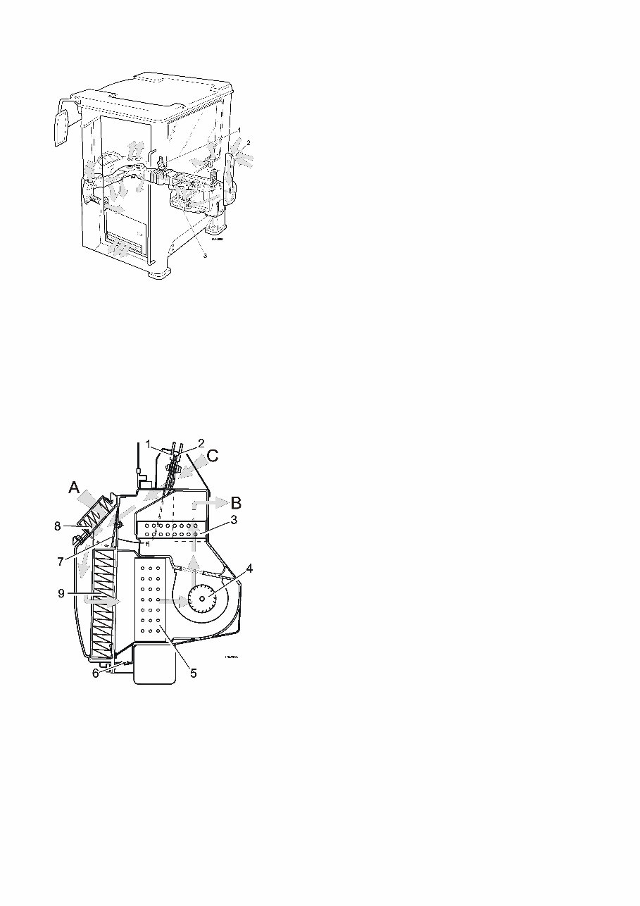
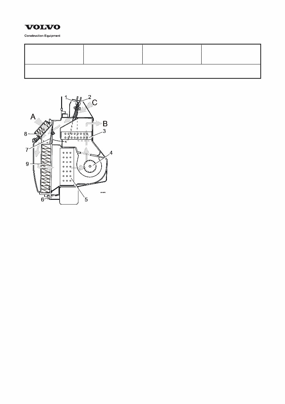
contributes to keeping the cab free of dust. Figure 2 Climate control system / air duct system The air sucked into the cab first passes through air intake A. It then goes through replaceable prefilter 8 which is accessible via a cover on the right side of the cab. The filter is supplemented by replaceable cab filter 9. After the air has passed the cab filter it is sucked into fan 4 via evaporator 5 (optional equipment) and then blown further through heater unit 3 after which it is distributed inside the cab. If recirculation is selected, most of the air will flow via recirculation damper 7 as shown by arrow C. With control 1 set at max. recirculation about 90% of the air will be recirculated and only about 10% taken from outside to maintain excess inside the cab. Figure 3 Climate control system, cross section 1 Recirculation control 7 Recirculation damper 2 Heater control 8 Prefilter 3 Heater unit 9 Cab filter 4 Fan motor A Air from outside the cab 5 Evaporator B Air into the cab 6 Drain valve for condensation water C Recirculation air
Service Information Document Title: Function Group: Information Type: Date: Climate control system, description 874 Service Information 2014/3/27 Profile: WLO, L50E [GB] Climate control system, description Figure 1 Climate control system, sectional view 1 Recirculation control 7 Recirculation damper 2 Heat control 8 Pre-filter 3 Heater unit 9 Cab filter 4 Fan motor A Outdoor air 5 Evaporator B Air inside cab 6 Drain valve for condensation C Recirculation air The evaporator (5) is located between the cab filter (9) and the fan (4). When the air-conditioning is started, the evaporator becomes cold and the air, which passes between the fins on the evaporator, is cooled down. If the air becomes too cold, it can be warmed to the required temperature with the aid of the heater unit (3). The air conditioning unit is filled with refrigerant R134a which is pumped round the system by compressor D.
Find the most complete service and repair manual for the VOLVO L50E WHEEL LOADER. This professional technical manual contains service, maintenance, and troubleshooting information for your VOLVO L50E WHEEL LOADER, making it useful for both professional mechanics and DIY enthusiasts. The manual has easy-to-read text sections with top-quality diagrams and instructions, specifically written for do-it-yourself work and experienced mechanics. It covers every single detail on your machine and provides step-by-step instructions based on the complete disassembly of the machine.
This manual service is packed with all the information you need and is very simple to use. Accurate, clear, and concise text combined with illustrations make it possible for anyone with even a bit of basic mechanical knowledge to safely and easily service and repair their VOLVO L50E WHEEL LOADER. Comprehensive diagrams, in-depth illustrations, and all the manufacturer's specifications and technical information you will need are included.
With our able Repair Manuals, find the page pertaining to your job, print it off, and get working on your machine. No more ruining your expensive paper shop manual with grease and dirt. You will have instant access to your manual, with no waiting or shipping fees. You can start doing your repairs right away!
If you are broken down on the trail or site and have a smartphone, our able Repair Manuals provide instant access to the material needed to get you running again. Kind of tough to do that with a paper manual.
Product Details:
File Format: .PDF
Language: English
Specifications: Full Printable
Zoom IN/OUT: YES
Delivery: Instant Access
Requirements: Adobe Reader & Win
Compatible: All Versions of Windows & Mac
Service and repair manual for VOLVO L50E WHEEL LOADER includes MOT Test Checks, Roadside Repairs, Routine Maintenance, Engine and Associated Systems, Cooling, Heating and Air Conditioning Systems, Fuel and Exhaust Systems, Engine Electrical Systems, Emissions Control Systems, Transmission, Manual Transmission, Automatic Transmission, Clutch and Driveshafts, Brakes, Braking System, Suspension, Suspension and Steering Systems, Body Equipment, Bodywork and Fittings, Electrical, Body Electrical Systems, Wiring Diagrams, Reference, Tools and Working Facilities, General Repair Procedures, Buying Spare Parts and Vehicle Identification Numbers, Fault Finding, and Glossary of Technical Terms.
VOLVO L50E WHEEL LOADER FULL SERVICE REPAIR MANUAL
Recently Viewed
5,521,897Happy Clients
2,594,462eManuals
1,120,453Trusted Sellers
15Years in Business
Price:
Actual Price:
VOLVO L50E Wheel Loader Full Service Repair Manual