Volvo L25B Compact Wheel Loader Service & Repair Manual
What's Included?
Lifetime Access
Fast Download Speeds
Offline Viewing
Access Contents & Bookmarks
Full Search Facility
Print one or all pages of your manual
Service Information Document Title: Function Group: Information Type: Date: General information to note when working on the hydraulic system 900 Service Information 2014/3/8 0 Profile: CWL, L25B [GB] General information to note when working on the hydraulic system NOTE! Precautionary measures to protect against possible risk of accident, injury or death. Special notes for better implementation of operating, control and adjustment procedures and maintenance work. The assemblies for power transmission, hydraulic adjustment motor, dropbox and axles should only be repaired in workshops which fulfil the following conditions and have the following equipment: trained staff prescribed tools and test instruments such as test bench, crack tester, special tools Genuine spare parts All work must be carried out with maximum care and conscientiousness. The safety regulations must be noted and observed. The regulations of the professional trade association concerned must be noted. NOTE! Before working on the hydraulic system, the lifting frame and hydraulic equipment must be supported mechanically with suitable means to prevent accidental lowering. The entire hydraulic system must be depressurized. One important condition is absolute cleanliness in removal and installation of components to be replaced or repaired. Prevent dirt and other contaminants from entering the system. Clean bolts, filler caps and their surroundings before removal, so that no dirt can penetrate. Before removing hoses, pipes and similar, turn off the engine and depressurize systems. During repair, seal all openings with clean plugs and caps. Remember to remove plugs and caps before installing. Do not wipe hydraulic components with lint cloth. When adding hydraulic oil to the tank, the oil must be added through a filter as even new oil in sealed containers does not meet the requirements imposed on clean hydraulic oil. Grease must not be used as an anti-seize compound when assembling hydraulic components; use hydraulic oil. If burrs and abraded particles are found in the hydraulic oil tank, flush and clean all circuits. For repairs, always fit genuine spare parts. Before removal, mark components to facilitate reassembly. For installation, always use new seals. Self-locking nuts must also be replaced. In all repair work, only use suitable tools and make adjustments only using the prescribed measuring tools. In principle, when fitting new components check the settings, i.e. the diesel engine and new components must be matched to each other. Check pressures and speeds (rpms). Check screw fittings and flanges for leaks. Check oil level in hydraulic oil tank and top up if necessary. NOTE! Only use hydraulic oil of the prescribed specification in the Operating Media table of the Operator's manual.
Service Information Document Title: Function Group: Information Type: Date: Cleanliness when working on hydraulic components 900 Service Information 2014/3/8 0 Profile: CWL, L25B [GB] Cleanliness when working on hydraulic components WARNING Hot hydraulic oil and hydraulic oil under pressure may result in severe personal injuries It is very important to keep the hydraulic system free from impurities as these can cause abnormal wear and can lead to expensive malfunctions. Extreme cleanliness should be observed when handling hydraulic components and hydraulic oil. NOTE! A vacuum pump should be used during work on the hydraulic system.
Service Information Document Title: Function Group: Information Type: Date: Hydraulic oil, storage and handling 900 Service Information 2014/3/8 0 Profile: CWL, L25B [GB] Hydraulic oil, storage and handling Hydraulic oil should be stored in tightly sealed tanks or barrels. Only containers used for transporting hydraulic oil should be used for this purpose. Oil should be stored under cover or in temperature–controlled premises. If oil is stored outdoors, the barrels should be stored horizontally so that water cannot enter and the barrel markings are not eradicated. Oil must not be stored at temperatures exceeding 60 °C (140 °F), or be exposed to direct sunlight or freezing temperatures.
Service Information Document Title: Function Group: Information Type: Date: Hydraulic system, repair of hydraulic components in workshop 900 Service Information 2014/3/8 0 Profile: CWL, L25B [GB] Hydraulic system, repair of hydraulic components in workshop Always wear clean coveralls and be strict about personal cleanliness. Work on hydraulic components should be performed separate from other work in a so-called "clean room". The room must have good ventilation and the floor must be coated with a binding material. Machining, grinding and similar work is not allowed in the "clean room". The workplace must be equipped with thoroughly cleaned tools and suitable containers for cleaning hydraulic components. Containers for cleaning hydraulic components must not be used for other cleaning. The containers must be cleaned frequently and filled with new fluid. The containers must be equipped with a removable grating on the bottom, which separates the component from any sludge on the bottom. Always clean components that are going to be handled in the "clean room". If an alkaline detergent is used, it should contain anti-corrosion agent. Always plan work on the hydraulic system so that it can be completed without any longer interruptions. When cleaning during repairing – use dry and clean compressed air for drying, do not use cotton waste or rags. Always plug a component when work is completed, use clean plastic plugs of the correct dimensions, and pack the component. When cleaning in the "clean room" – use methods which do not stir up dust or dirt.
Service Information Document Title: Function Group: Information Type: Date: Hydraulic components, storage and transport 900 Service Information 2014/3/8 0 Profile: CWL, L25B [GB] Hydraulic components, storage and transport All hydraulic components must be stored in plastic bags or film and they must be plugged. The packaging must not be opened before the component is to be used. Service vehicles should be equipped with an interior which facilitates good order and cleanliness. Each service vehicle should carry a roll of plastic film, plastic plugs of the most common sizes and plastic containers for components. Plugs and film should be of the disposable type.
Service Information Document Title: Function Group: Information Type: Date: Troubleshooting chart 900 Service Information 2014/3/8 0 Profile: CWL, L25B [GB] Troubleshooting chart Malfunction/Error Possible malfunction cause Malfunction elimination Hydraulic functions of raise, tilt, lock, cannot be performed Oil level in hydraulic oil tank too low. Pressure lines faulty or line connections leaking. Line connections incorrect. Delivery volume of working hydraulics pump too low. Add hydraulic oil and bleed system if necessary. Check pressure lines for condition and connections for leaks, replace or tighten connections if necessary. Test line connections for correct connection. Test delivery volume of working hydraulics pump, replace if necessary. Power loss in working hydraulics. Oil level in hydraulic oil tank too low. Pressure lines faulty or line connections leaking. Pressure lines crushed or twisted. Working pressure too low. Primary pressure limiting valve dirty or faulty. Inner leakage of working hydraulics pump too great. Suction–return filter in hydraulic oil tank dirty. Add hydraulic oil and bleed system. Check pressure lines for condition and connections for leaks, replace or tighten connections if necessary. Check line routing, route correctly or change. Test working pressure, if necessary adjust on primary pressure limiting valve. Test inner leakage of working hydraulics pump, change if necessary. Check filter element, replace if necessary. Working hydraulics work too slow and system becomes too hot. NOTE: For malfunction cause and elimination, see all points under "Hydraulic functions of raise, tilt, lock, cannot be performed" and "Power loss in working hydraulics". Suction line from hydraulic oil tank to working hydraulics pump leaking. Incorrect oil in hydraulic oil tank. Seals or O–rings on working cylinders leaking. Check suction lines and connections on hydraulic oil tank and working hydraulics oil pump, tighten connections or replace hose if necessary. Drain oil from the hydraulic oil tank, flush the system and add hydraulic oil of the prescribed specification according to the table of operating media. Check for inner and outer leaks on working cylinders, if necessary replace seals and O–rings. Lifting frame lowers with control valve in neutral position. Seals or O–rings on lifting cylinders leaking. Lifting cylinders or piston rods damaged. Secondary limiting valve dirty or seal faulty. Secondary limiting valve damaged. Control valve leaking. Check for inner and outer leaks on lifting cylinders, if necessary replace seals and O–rings. Test lifting cylinders, if necessary replace fully. Test secondary limiting valve, change if necessary. Test control valve. if necessary replace Bucket tilts out or back with control valve in neutral position. Seals or O–rings on tilt cylinders leaking. Tilt cylinders or piston rods damaged. Secondary limiting valves with feed valve dirty or seal faulty. Secondary limiting valves with feed valve damaged. Control valve leaking. Check for inner and outer leaks on tilt cylinders, if necessary replace seals and O–rings. Test tilt cylinders, replace fully if necessary. Test secondary limiting valves with feed valve, clean and replace O–ring if necessary. Test control valve. if necessary replace Lifting frame lowers slightly first on fine control "raise". Non-return valve (load-holding valves) "raise/lower" faulty or seat damaged. Check non-return valve and valve seat, if necessary replace non-return valve Bucket first tilts slightly Non-return valve (load-holding valves) Check non-return valve and valve seat, if
forward on fine control "tilt back". "tilt back/out" faulty or seat damaged. necessary replace non-return valve Control valve leaking on outside. Oil level in hydraulic oil tank too low. Return filter dirty. Lines chafing. Working hydraulics pump draws in air, or there is air in the system. Pressure lines faulty or crushed. Working hydraulics pump faulty. Add hydraulic oil and bleed system if necessary. Check return filter, replace filter element if necessary. Route lines properly and attach, or replace. Eliminate leaks and bleed system. Check pressure lines for condition and connections for leaks, replace or tighten connections if necessary. Check suction line, replace if necessary. Test working hydraulics pump, replace if necessary. Abnormal noise from working hydraulics pump or in the hydraulic system. Oil level in hydraulic oil tank too low Suction return filter dirty Lines chafing Working hydraulics pump draws in air, or there is air in the system Pressure line faulty or line connections leaking. Suction line faulty or crushed, working hydraulics pump faulty. Add hydraulic oil and bleed system if necessary Check suction/return filter, replace filter element if necessary Route lines properly and attach, or replace Eliminate leaks and bleed system Check pressure lines for condition and connections for leaks, replace or tighten connections if necessary Check suction line, replace if necessary Test working hydraulics pump, replace if necessary
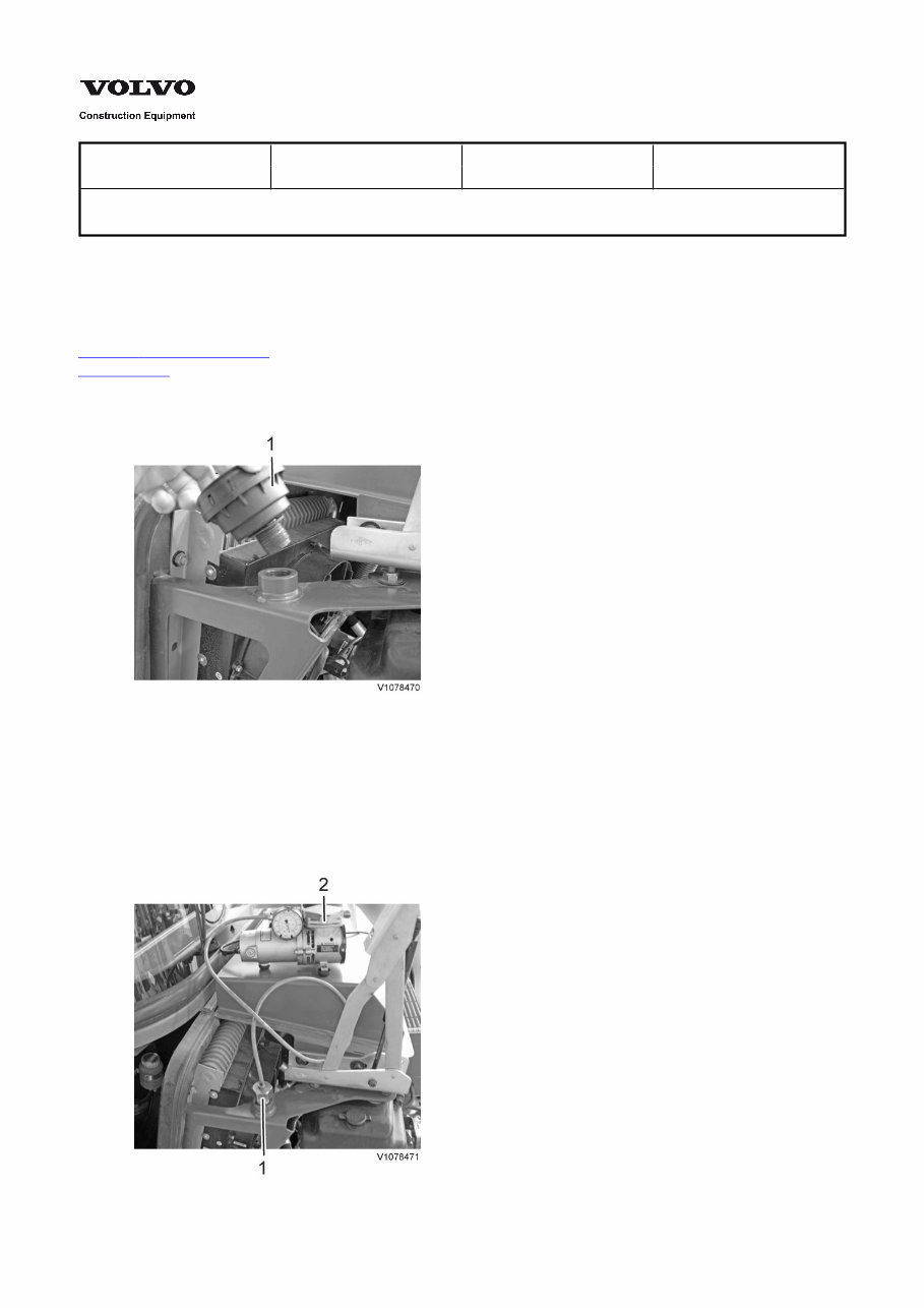
Service Information Document Title: Function Group: Information Type: Date: Vacuum pump, connection 900 Service Information 2014/3/8 0 Profile: CWL, L25B [GB] Vacuum pump, connection Op nbr 900-005 14360000 Vacuum pump / 24V 9809685 Cable 1. Place the machine in the service position and open the engine hood. Figure 1 2. Unscrew bleed valve (1). 3. Screw in adapter (1) and install connection of vacuum pump (2). NOTE! If it is not possible to provide power with the battery disconnect switch, use cable 9809685. Figure 2
4. Switch on the vacuum pump. There is now a partial vacuum in the hydraulic oil tank so that certain operations can be performed on the hydraulic system without having to drain hydraulic oil. NOTE! Never allow the vacuum pump to run unattended. Loss of power could cause malfunction. Remove 5. Turn off the vacuum pump and remove it. 6. Unscrew the adapter and screw on the bleed valve. 7. Test machine operation.
Service Information Document Title: Function Group: Information Type: Date: Hydraulic system, description 910 Service Information 2014/3/8 0 Profile: CWL, L25B [GB] Hydraulic system, description The hydraulic system on the machine consists of the steering, driving and working hydraulics. The oil circuit is thermostatically regulated, with integrated cooling system. The mechanically controlled double-action control valve consists of three sections. The gear pump which is flanged to the through drive of the hydrostatic pump supplies oil to the working hydraulics. The hydraulic oil tank is common to the steering, driving and working hydraulic system. The hydraulic tank contains a combined suction and return filter. It is vented through a bleed and ventilation filter.
Get the complete factory service repair workshop manual for the Volvo L25B Compact Wheel Loader. This professional manual is available for instant access on your computer, tablet, or smartphone. It covers all repairs, servicing, and troubleshooting procedures with detailed photos, diagrams, and step-by-step instructions. It is a valuable resource for both professional mechanics and DIY enthusiasts.
With this manual, you can print out a single page or the entire manual as per your requirement. It can be used on multiple computers without any limitations or trial periods. There is no expiration, renewal fee, or additional cost – it's a lifetime access manual. It is fully compatible with Windows and MAC computers.
Click the button to get your hands on this comprehensive manual and ensure you have the essential information for maintaining and repairing your Volvo L25B Compact Wheel Loader.
Recently Viewed
5,521,897Happy Clients
2,594,462eManuals
1,120,453Trusted Sellers
15Years in Business
Price:
Actual Price:
Volvo L25B Compact Wheel Loader Service & Repair Manual