

Volvo L20B Compact Wheel Loader Service & Repair Manual
What's Included?
Fast Download Speeds
Offline Viewing
Access Contents & Bookmarks
Full Search Facility
Print one or all pages of your manual
Service Information
Document Title: Function Group: Information Type: Date:
Description 000 Service Information 2014/3/6 0
Profile:
CWL, L20B [GB]
Description
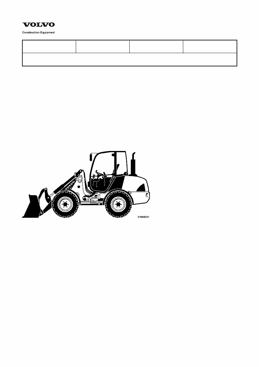
The L20B wheel loader has a central articulating oscillating joint and four-wheel drive. The lifting frame is equipped with a
hydraulic quick-change attachment bracket. Parallel kinematics provide high breakout force and exact parallel guidance
when lifting.
The engine is a four-cylinder, four-stroke, in-line diesel engine with direct injection and oil/air cooling.
The hydrostatic transmission provides full power shift under load, both when changing direction (forward and reverse) and
between ranges. Maximum drawbar force can be achieved in all ranges. The "inch/brake pedal" provides variable machine
speed control and power transfer.
The front and rear axles are planetary rigid axles with 100% hydraulically engagable/disengagable differential locks on both
axles.
The service brake is a drum brake acting on the wheels of the front axle and is operated via the "inch/brake pedal".
The parking brake is a drum brake acting on the wheels of the front axle upon mechanical engagement.
The hydraulic system is a thermostatically regulated oil circuit with integrated cooling system. Three-spool control valve with
primary and secondary fuse protection.
Figure 1
Service Information
Document Title: Function Group: Information Type: Date:
Tightening torques 030 Service Information 2014/3/6 0
Profile:
CWL, L20B, L25B [GB]
Tightening torques
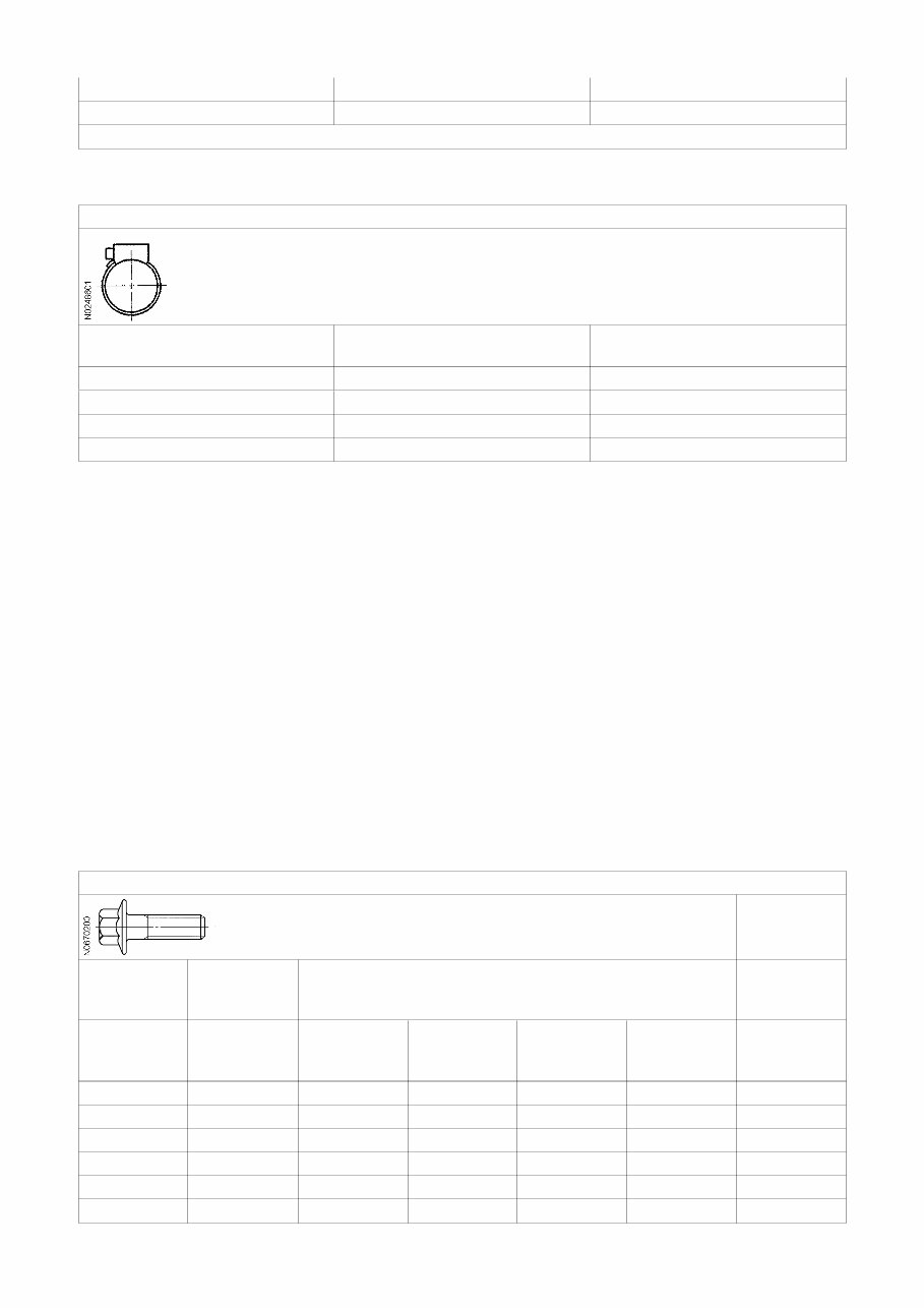
Wheel nuts
Wheel nuts
Thread M Wrench size (width across flats) Tightening torque (Nm)
M22 x 1.5 30 560 – 600
Hydraulic connections, general
Before fitting pipe couplings, plugs and hoses:
Make sure that the sealing surfaces are clean and free from pores or scratches.
Check elastic seal rings for defects.
Oil in threads, sealing surfaces and contact surfaces except for ORFS-connections (ORFS = O-Ring Face Seal).
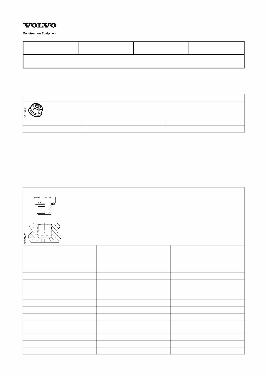
Valve connections
Valve connections, ORFS-connections with ED seals (DIN 3852 form E)
Connection thread (mm) Wrench size, width across flats (mm) Tightening torque (Nm)
M10 x 1.0 19
M12 x 1.5 17 37
M14 x 1.5 22 58
M16 x 1.5 22 74
M18 x 1.5 24 94
M20 x 1.5 130
M22 x 1.5 27 140
M27 x 2.0 32 190
M33 x 2.0 41 330
M42 x 2.0 50 470
M48 x 2.0 55 570
Connection thread (inches) Wrench size, width across flats (mm) Tightening torque (Nm)
G 1/8 17 alt. 19 19
G 1/4 19 alt. 22 58
G 3/8 22 alt. 27 84
G 1/2 27 alt. 32 120
G 3/4 32 alt. 41 190
G 1 41 alt. 46 330
G 1 1/4 50 470
G 1 1/2 55 570
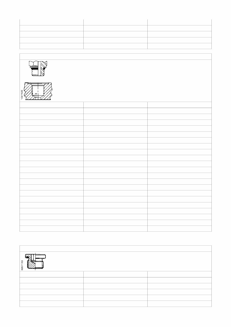
Valve connections, ORFS-connections with O-ring seals (ISO 6149)
Connection thread (mm) Wrench size, width across flats (mm) Tightening torque (Nm)
M8 x 1.0 11
M10 x 1.0 21
M12 x 1.5 17 alt. 19 37
M14 x 1.5 19 alt. 22 47
M16 x 1.5 22 58
M18 x 1.5 24 alt. 27 74
M22 x 1.5 27 alt. 32 110
M27 x 2.0 32 180
M33 x 2.0 32, 41 alt. 46 330
M42 x 2.0 50 350
M48 x 2.0 55 440
Connection thread (inches) Wrench size, width across flats (mm) Tightening torque (Nm)
7/16 – 20 UNF 16 21
1/2 – 20 UNF 26
9/16 – 18 UNF 19 37
3/4 – 16 UNF 22 74
7/8 – 14 UNF 27 110
1 1/16 – 12 UNF 41 180
1 5/16 – 12 UNF 41 284
1 5/8 – 12 UNF 50 300
1 7/8 – 12 UNF 55 390
Blanking plugs
Blanking plugs with ED seal
Connection thread (mm) Allen key dim. (mm) Tightening torque (Nm)
M10 x 1.0 5 12
M12 x 1.5 6 25
M14 x 1.5 6 35
M16 x 1.5 8 55
M18 x 1.5 8 65
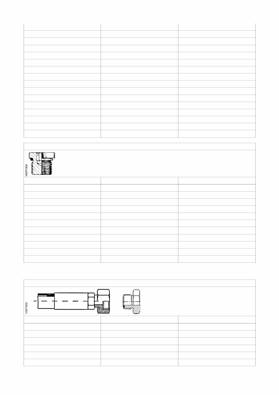
M20 x 1.5 10 80
M22 x 1.5 10 90
M26 x 1.5 12 100
M27 x 2.0 12 140
M33 x 2.0 17 230
M42 x 2.0 22 360
M48 x 2.0 24 360
Connection thread (inches) Allen key dim. (mm) Tightening torque (Nm)
G 1/8 5 13
G 1/4 6 30
G 3/8 8 60
G 1/2 10 80
G 3/4 12 140
G 1 17 200
G 1 1/4 22 400
G 1 1/2 24 450
Blanking plugs with O-ring seal (ISO 6149)
Connection thread (mm) Allen key dim. (mm) Tightening torque (Nm)
M10 x 1.0 5 20
M12 x 1.5 6 35
M14 x 1.5 6 45
M16 x 1.5 8 55
M18 x 1.5 8 70
M20 x 1.5 10 80
M22 x 1.5 10 100
M26 x 1.5 12 130
M27 x 2.0 12 170
M33 x 2.0 14 310
M42 x 2;0 22 330
ORFS-connections
ORFS-connections (ISO 8434-3)
Thread (inches) Wrench size, width across flats (mm) Tightening torque (Nm) *
9/16 – 18 UNF 17 alt. 19 25
11/16 – 16 UN 22 35
13/16 – 16 UN 24 55
1 – 14 UNS 30 85
1 3/16 – 12 UN 36 120
1 7/16 – 12 UN 41 alt. 46 160
1 11/16 – 12 UN 50 200
2 – 12 UN 60 260
* Threads and sealing surface must not be oiled in before tightening.
Hose clamps
Hose clamps with worms
Intended for hose outside diameter
(mm)
Wrench size, width across flats (mm) Tightening torque (Nm)
10 – 19 7 2.5
20 – 30 7 3.5
31 – 49 7 4.5
50 – 231 7 5.5
Bolts and nuts
The pretensioning force achieved at a given tightening torque depends on the coefficient of friction of the bolted joint.
The coefficient of friction in turn depends on the surface texture, surface treatment and lubricated condition. The values are
calculated assuming a coefficient of friction of 0.2 for a dry chromated flange bolt and 0.15 for a lubricated chromated
flange bolt. The lower torque for Allen bolts and traditional hex bolts, in relation to flange bolts, is due to the shorter torque
arm for the frictional force under the bolt head (smaller diameter of bolt head).
The following abbreviations for surface treatment are used in the tables:
Fe/Zn-Fe = Black chromated zinc - iron
FZB = Blank chromated
NOTE!
In some body parts, there are weld bolts with much lower strength than normal bolts of the same dimension.
NOTE!
When Nordloc washer is used, increase the torque by 20%.
NOTE!
Bolts provided with liquid alt. micro-capsuled thread locker or thread sealant shall be tightened with the same torque as a
lubricated bolt of the same type.
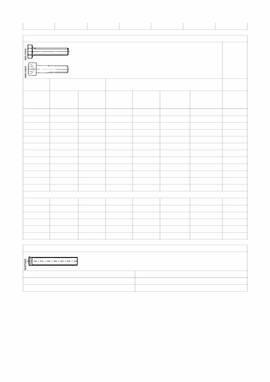
Flange bolts
Blind rivet nut
Thread (mm) Wrench size,
width across
flats (mm)
Torque (Nm) Torque (Nm)
8.8 Fe/Zn-Fe
Dry
8.8 Fe/Zn-Fe
Lubricated
10.9
Phosphated
10.9
Phosphated
Lubricated
Dry
M5 8 7 6 6
M6 10 12 10 10
M8 12 28 24 24
M10 14 56 48 70 60 48
M12 17 100 85 125 105 82
M14 18 160 140 200 175
M16 21 250 220 320 275
Hex bolts and Allen head bolts
Blind rivet
nut
Wrench size (width across
flats)
Torque (Nm) Torque
(Nm)
Thread
(mm/inch)
Hex bolt
(mm/inch)
Allen head
bolt (mm/
inch)
8.8 FZB &
Fe/Zn-Fe
Dry
8.8 FZB &
Fe/Zn-Fe
Lubricated
10.9
Phosphated
Lubricated
12.9 Untreated
Lubricated
Dry
M5 8 4 6 5 6
M6 10 5 10 9 20 10
M8 13 6 25 22 40 24
M10 16 8 50 44 60 80 48
M12 18 10 90 75 105 140 82
M14 21 12 140 125 175 220
M16 24 14 220 190 275 340
M20 30 17 450 380 540 650
M24 36 19 770 660 900 1 120
M27 41 – 1 100 940 1 350 1 620
M30 46 22 1 500 1 280 1 840 2 210
M36 55 2 500 2 300 3 210 3 850
1/4 UNC 7/16 3/16 12 10 15 20
5/16 UNC 1/2 1/4 25 21 30 40
3/8 UNC 9/16 5/16 45 38 55 70
7/16 UNC 5/8 65 55 90
1/2 UNC 3/4 3/8 100 85 130 170
9/16 UNC 13/16 145 123 190
Nuts on weld bolts (material S235JRG2-EN 10025)
Thread Torque (Nm)
M6 5
M8 12
Tolerances
Modern high-quality torque wrenches normally give a variation of ± 5 % of the indicated value. This, together with variations
in friction coefficient, gives a range in the pretensioning force of approximately ± 16 % for lubricated bolted joints and ± 29
% for dry bolted joints.

Service Information
Document Title: Function Group: Information Type: Date:
Conversion tables 030 Service Information 2014/3/6 0
Profile:
CWL, L20B, L25B [GB]
Conversion tables
Length
Unit cm m km in ft yd mile
cm 1 0.01 0.00001 0.3937 0.03281 0.01094 0.000006
m 100 1 0.001 39.37 3.2808 1.0936 0.00062
km 100000 1000 1 39370.7 3280.8 1093.6 0.62137
in 2.54 0.0254 0.000025 1 0.08333 0.02777 0.000015
ft 30.48 0.3048 0.000304 12 1 0.3333 0.000189
yd 91.44 0.9144 0.000914 36 3 1 0.000568
mile 160930 1609.3 1.6093 63360 5280 1760 1
1 mm = 0.1 cm - 1 mm = 0.001 m
Area
Unit cm2 m2 km2 a ft2 yd2 in2
cm2 1 0.0001 - 0.000001 0.001076 0.000012 0.155000
m2 10000 1 0.000001 0.01 10.764 1.1958 1550.000
km2 - 1000000 1 10000 1076400 1195800 -
a 0.01 100 0.0001 1 1076.4 119.58 -
ft2 - 0.092903 - 0.000929 1 0.1111 144.000
yd2 - 0.83613 - 0.008361 9 1 1296.00
in2 6.4516 0.000645 - - 0.006943 0.000771 1
1 ha = 100 a - 1 mile2 = 259 ha = 2.59 km2
Volume
Unit cm3 = cc m3 l in3 ft3 yd3
cm3 = ml 1 0.000001 0.001 0.061024 0.000035 0.000001
m3 1000000 1 1000 61024 35.315 1.30796
dm3(l) 1000 0.001 1 61.024 0.035315 0.001308
in3 16.387 0.000016 0.01638 1 0.000578 0.000021
ft3 28316.8 0.028317 28.317 1728 1 0.03704
yd3 764529.8 0.76453 764.53 46656 27 1
1 gal (US) = 3785.41 cm3 = 231 in3 = 0.83267 gal (UK)
Weight
Unit g kg t oz lb
g 1 0.001 0.000001 0.03527 0.0022
kg 1000 1 0.001 35.273 2.20459
t 1000000 1000 1 35273 2204.59

oz 28.3495 0.02835 0.000028 1 0.0625
lb 453.592 0.45359 0.000454 16 1
1 ton (metric) = 1.1023 ton (US) = 0.9842 ton (UK)
Pressure
Unit kp/cm2 bar Pa=N/m2 kPa lbf/in2 lbf/ft2
kp/cm2 1 0.98067 98066.5 98.0665 14.2233 2048.16
bar 1.01972 1 100000 100 14.5037 2088.6
Pa=N/m2 0.00001 0.001 1 0.001 0.00015 0.02086
kPa 0.01020 0.01 1000 1 0.14504 20.886
lbf/in2 0.07032 0.0689 6894.76 6.89476 1 144
lbf/ft2 0.00047 0.00047 47.88028 0.04788 0.00694 1
kg/cm2 = 735.56 Dry (mmHg) = 0.96784 atm
Unit explanations
Unit abbreviation
Newton meter Nm
Kilopoundmeter kpm
Kilopascal kPa
Megapascal MPa
Kilowatt kW
kilojoule kJ
British thermal unit Btu
Calorie ca
Approx. conversion
SI unit Conversion
factor
Non SI Conversion factor SI
Torque
Nm x10.2 =kg/cm x0.8664 =lb in
Nm x0.74 =lbf·ft x1.36 =Nm
Nm x0.102 =kg/m x7.22 =lbft
Pressure (Pa = N/m2)
kPa x4.0 =in.H2O x0.249 =kPa
kPa x0.30 =in.Hg x3.38 =kPa
kPa x0.145 =psi x6.89 =kPa
bar x14.5 =psi x0.069 =bar
kp/cm2 x14.22 =psi x0.070 =kp/cm2
N/mm2 x145.04 =psi x0.069 =bar
MPa x145 =psi x0.00689 =MPa
Power (W = J/s)
kW x1.36 =hp(cv) x0.736 =kW
kW x1.34 =bhp x0.746 =kW
kW x0.948 =Btu/s x1.055 =kW
W x0.74 =ft·lb/s x1.36 =W
Energy (J = Nm)
kJ x0.948 =Btu x1.055 =kJ
Figure 1
J x0.239 =calorie x4.19 =J
Speed and acceleration
m/s2 x3.28 =ft/s2 x0.305 =m/s2
m/s x3.28 =ft/s x0.305 =m/s
km/h x0.62 =mph x1.61 =km/h
Horsepower/torque
Bhp x5252 rpm= TQ (lb·ft) TQ x rpm 5252=bhp
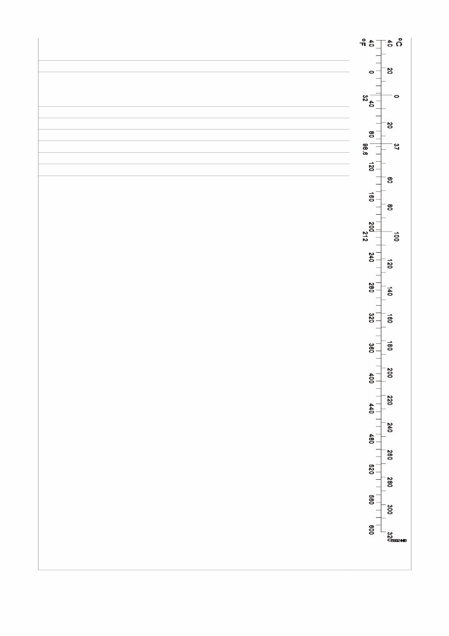
Temperature
ºC =(ºF-32)/1.8 ºF =(ºC x1.8) +32
Flow factor
l/min (dm3/min) x0.264 = US gal/min x3.785 =liter/min
Service Information
Document Title: Function Group: Information Type: Date:
Machine, transporting 050 Service Information 2014/3/6 0
Profile:
CWL, L20B [GB]
Machine, transporting
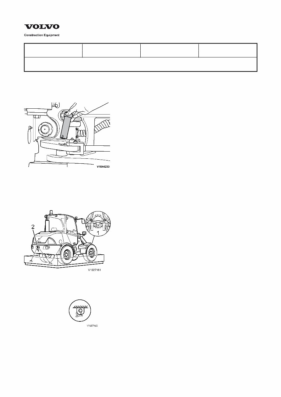
Steering joint lock
When transporting the machine on a trailer or by rail, the articulated steering joint must be locked with the steering lock.
Figure 1
Steering joint lock
Also, the machine must be lashed down to the loading surface of the transport vehicle so that it cannot tip over or roll away.
Block the wheels with chocks.
Figure 2
Lashing the machine
Marker plate for lashing
1.
2.
Fixing eyes on front frame
Fixing eyes on rear frame (towing device)
Lifting of machine
You're Reading a Preview
What's Included?
Fast Download Speeds
Offline Viewing
Access Contents & Bookmarks
Full Search Facility
Print one or all pages of your manual
$39.99
Viewed 27 Times Today


Secure transaction
What's Included?
Fast Download Speeds
Offline Viewing
Access Contents & Bookmarks
Full Search Facility
Print one or all pages of your manual
$39.99
The Volvo L20B Compact Wheel Loader Service & Repair Manual is a comprehensive factory workshop manual designed for instant access on your computer, tablet, or smartphone. This professional manual is an invaluable resource for both professional mechanics and DIY enthusiasts, covering all repair, servicing, and troubleshooting procedures with detailed step-by-step instructions, exploded diagrams, and photographs.
Key Features:
- Complete factory service repair workshop manual
- No extra fees or expiry dates
- Printable pages with no limitations
- Multi-computer usage
- Full compatibility with Windows & MAC computers
With no trial periods or renewal fees, this full manual provides lifetime access for all your repair and maintenance needs. Click the button to get your hands on this invaluable resource.


