

Volvo L120F Wheel Loader Full Service & Repair Manual
What's Included?
Fast Download Speeds
Offline Viewing
Access Contents & Bookmarks
Full Search Facility
Print one or all pages of your manual
Service Information
Document Title: Function Group: Information Type: Date:
Cab, removing 810 Service Information 2014/5/8 0
Profile:
WLO, L120F [GB]
Go back to Index Page
Cab, removing
Op nbr 810-001
14360000 Vacuum pump / 24V
88830070 Plug
88830070 Plug
88830070 Plug
88830070 Plug
88830070 Plug
88830070 Plug
88830070 Plug
88830070 Plug
88830070 Plug
88830070 Plug
Sling 4 m (13 ft), 2 pcs.
Lifting eye M16, 4 pcs.
Shackle 4 pcs.
Hose pliers, 4 pcs
NOTE!
Do not loosen any hoses or connections for the air conditioning, as this will lead to accidental release of refrigerant.
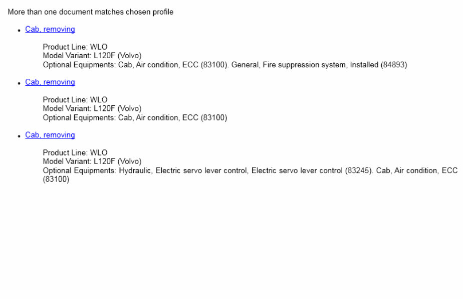
Figure 1
1.
2.
Squib cable (gas generator cable)
Electric power cable
1. Place the machine in service position 1, see .
191 Service position
2. Disconnect the (red) electric power cable and squib cable (gas generator cable) from the control unit to deactivate
the fire suppression system.
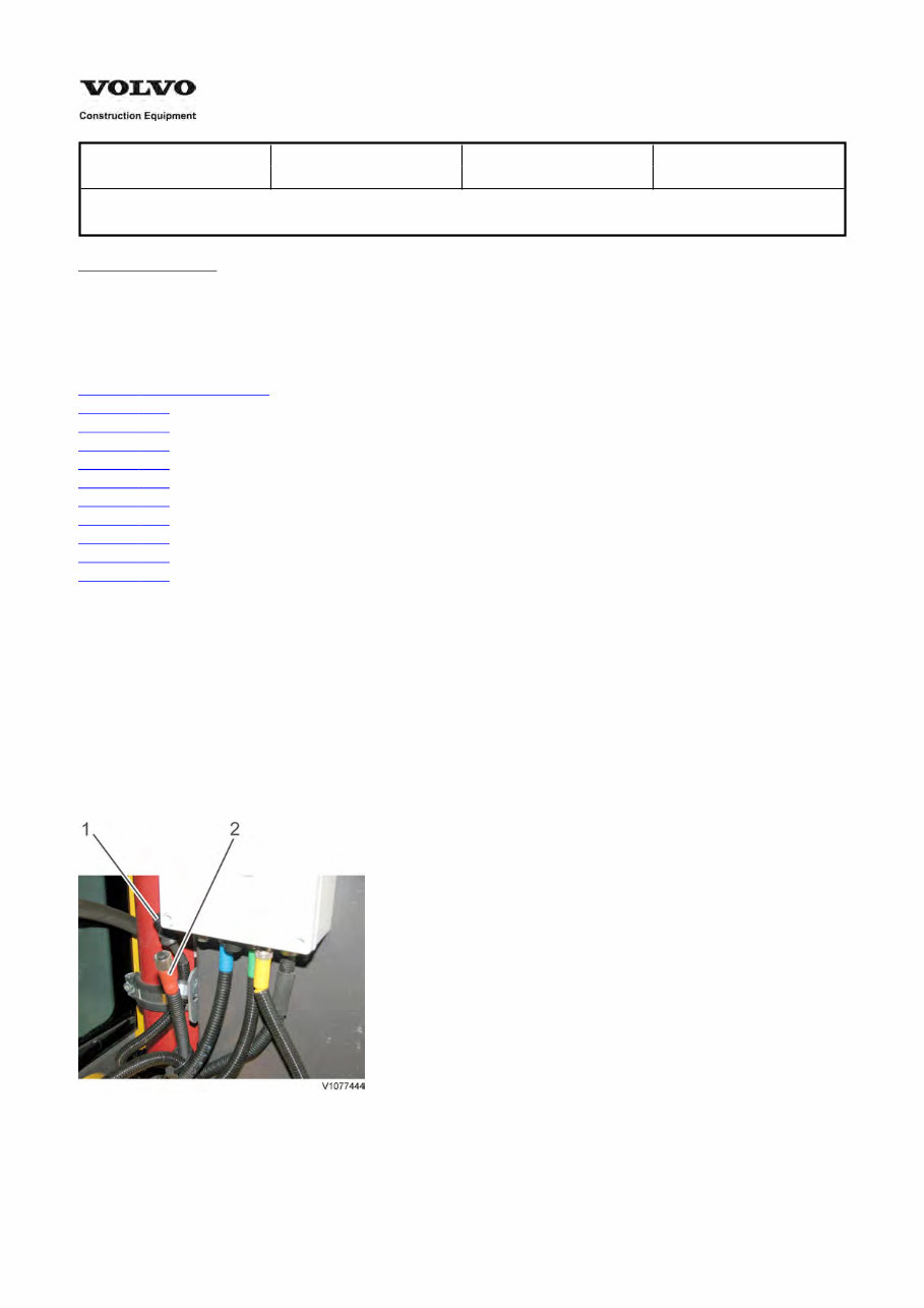
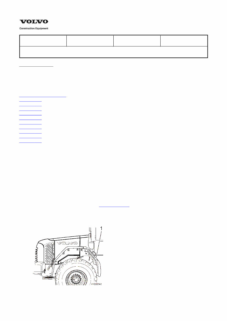
3. Remove the front part of the rear fender on the machine's right and left side. Weight, approx. 35 kg (80 lbs).
Remove the cover plate behind the front part of the rear fender on the machine's right side.
Figure 2
1. Front part of rear mudguard
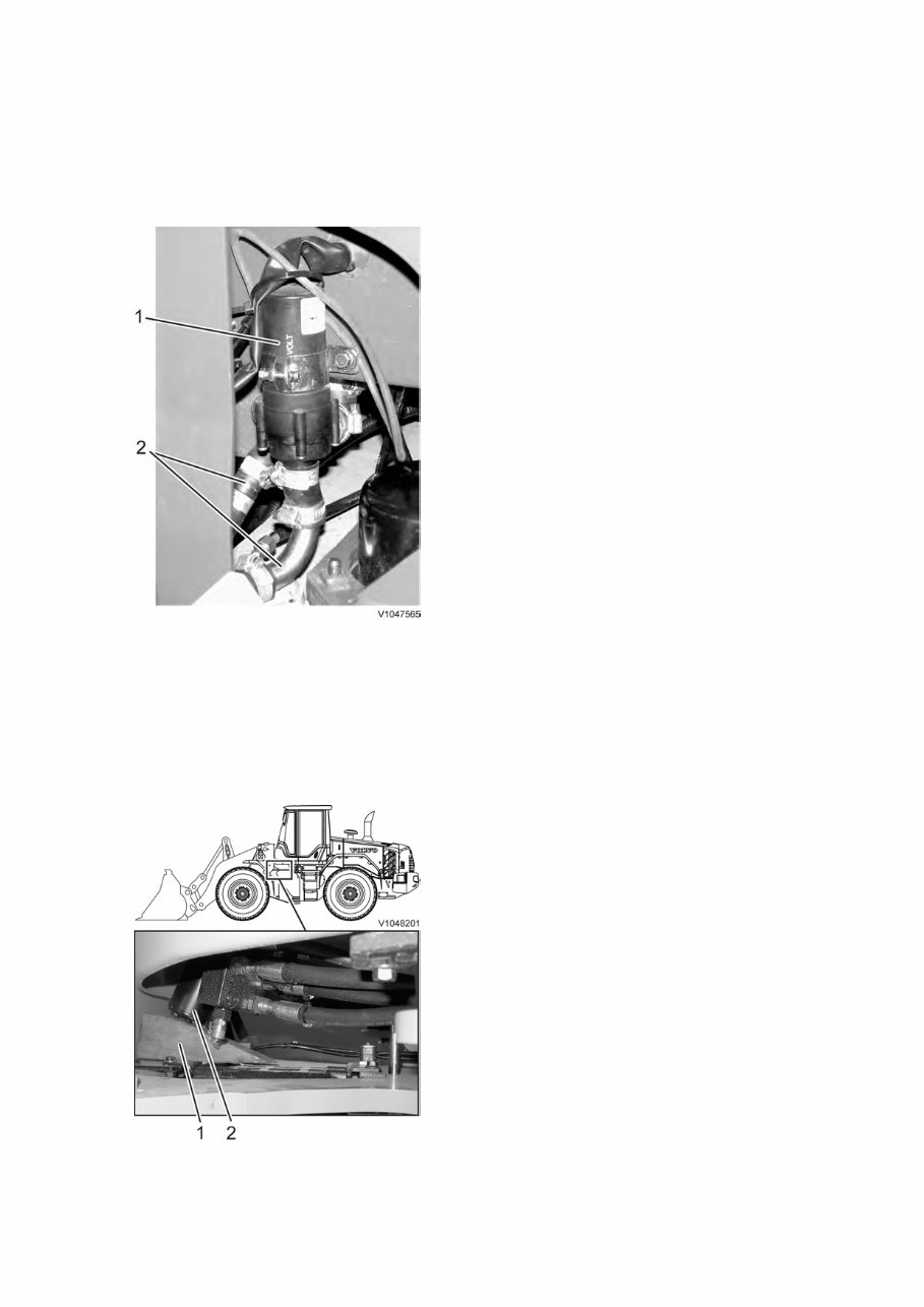
4. Part the washer fluid hoses by the non-return valves.
Figure 3
1. Junction pieces washer fluid
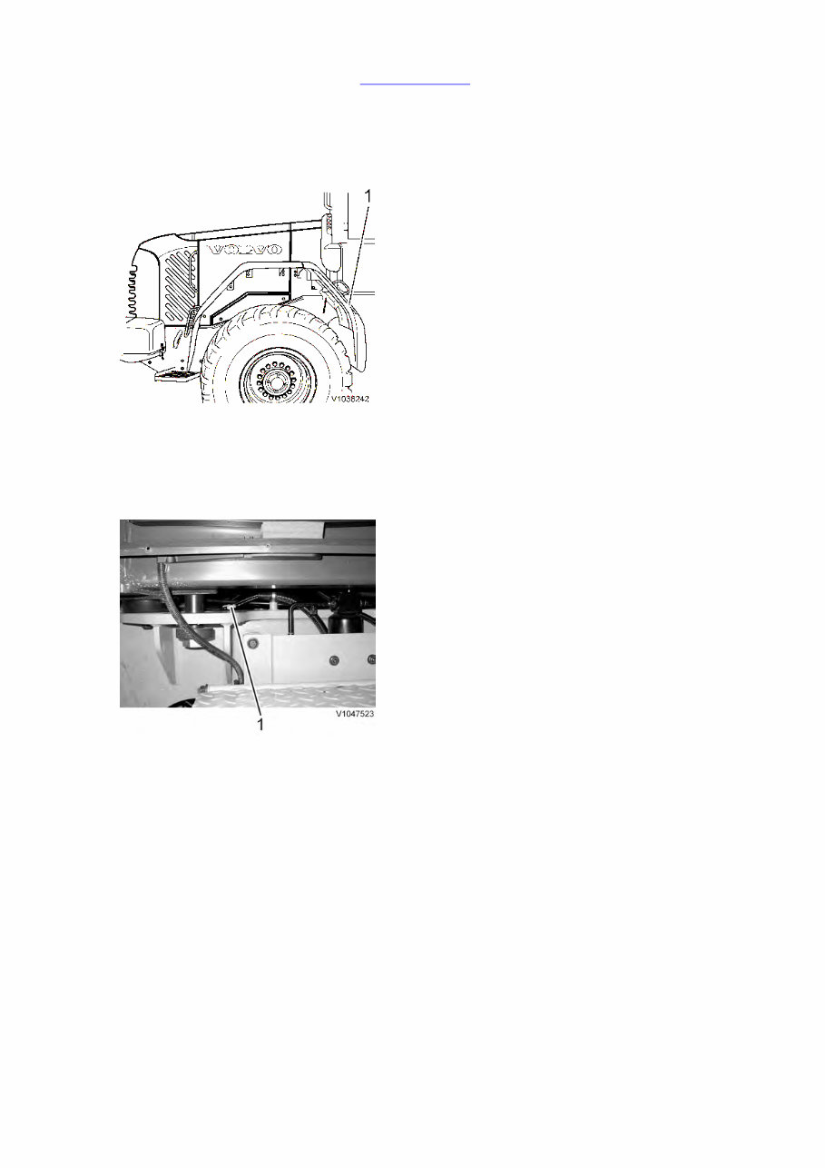
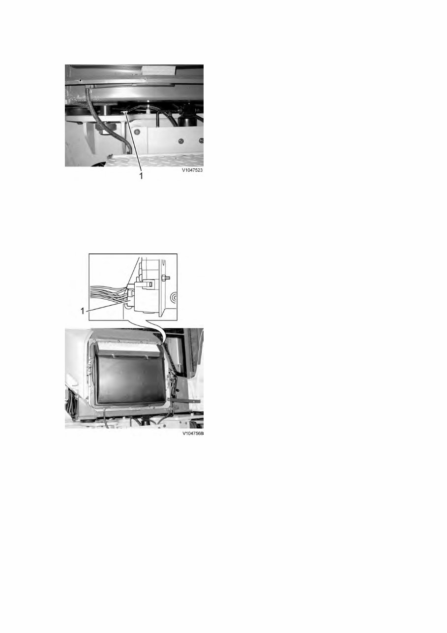
5. Remove the plastic casing together with the air filters.
Remove the plate and unplug the connector for the recirculation damper, MO8703.
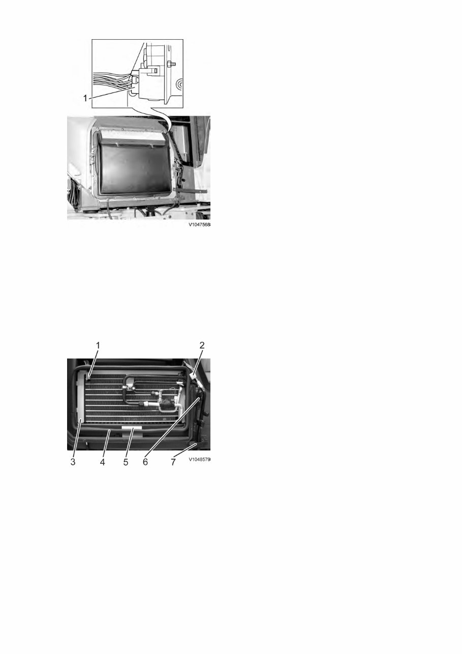
Figure 4
1. Connector
6. Unplug the connector for the pressure monitor, SE8709, and cut the cable ties.
Pull out the hose from the cab's temperature sensor.
Remove the sealing strip and the protective plate.
Loosen the bolt for the clamp.
Press out the plastic on the right side of the evaporator so that the lug on the evaporator releases. Swing out the
attaching plate together with the evaporator and lay it on the steps.
Figure 5
1.
2.
3.
4.
5.
6.
7.
Hose from cab's temperature sensor
Connector recirculation damper
Attaching plate
Sealing strip
Protective plate
Connector for pressure monitor SE8709
Clamp
7. Remove the protective casing located over the cable harnesses at the back to the left on the cab wall. Disconnect
the electrical terminals and detach the belt retaining the cable harness.
8. If the machine is equipped with rear vision camera: [ 1]
Remove the cover plate in front of the engine cover.
Disconnect the cable from rear vision camera.
Cut the ties keeping the cable harness together at the rear vision camera.
Pull out the cable by the cab, bundle together in a suitable way and attach to the cab.
9. Clamp the coolant hoses with the aid of hose pliers.
Disconnect the coolant hoses from the cab.
Figure 6
1.
2.
Pause heat pump [ 2]
Coolant hoses
10. Remove the cover plates by the cab's bottom part on the machine's right and left side. [ 3]
11. Install a wedge under the steering valve so that it does not fall down when the attaching bolts are removed.
Figure 7

1.
2.
Wedge
Steering valve
12. Remove the accelerator pedal and the right brake pedal. Remove the front floor mat.
Remove the four bolts that hold the steering valve. Remove the wedge and lay down the steering valve on the
frame.
Figure 8
1. Screw, x 4
13. Unplug the connector for the brake pressure sensor, SE5205, on the foot brake valve.
Remove the nuts for the attaching bolts and let down the foot brake valve on the frame.
Figure 9
1.
2.
3.
4.
Adjusting max. output brake pressure
Nut for attaching bolt, 4 pcs.
Pressure check connection
Sensor SE5205
14. Switch on the battery disconnect switch.
Connect the vacuum pump, see .
911 Hydraulic oil tank, vacuum-pumping, connecting and disconnecting pump
15. Remove the front floor plate.
16. Release the tensioning strap retaining the hydraulic hoses. Remove the safety catch. Press in the coupling and part
all couplings to the control lever carrier. Plug the hoses.
Collect the waste oil in a suitable vessel.
Figure 10
1.
2.
3.
Quick-couplings lever carrier
Safety catch
Tensioning strap
17. Remove the vacuum pump according to
.
911 Hydraulic oil tank, vacuum-pumping, connecting and disconnecting pump
18. Turn off the battery disconnect switch.
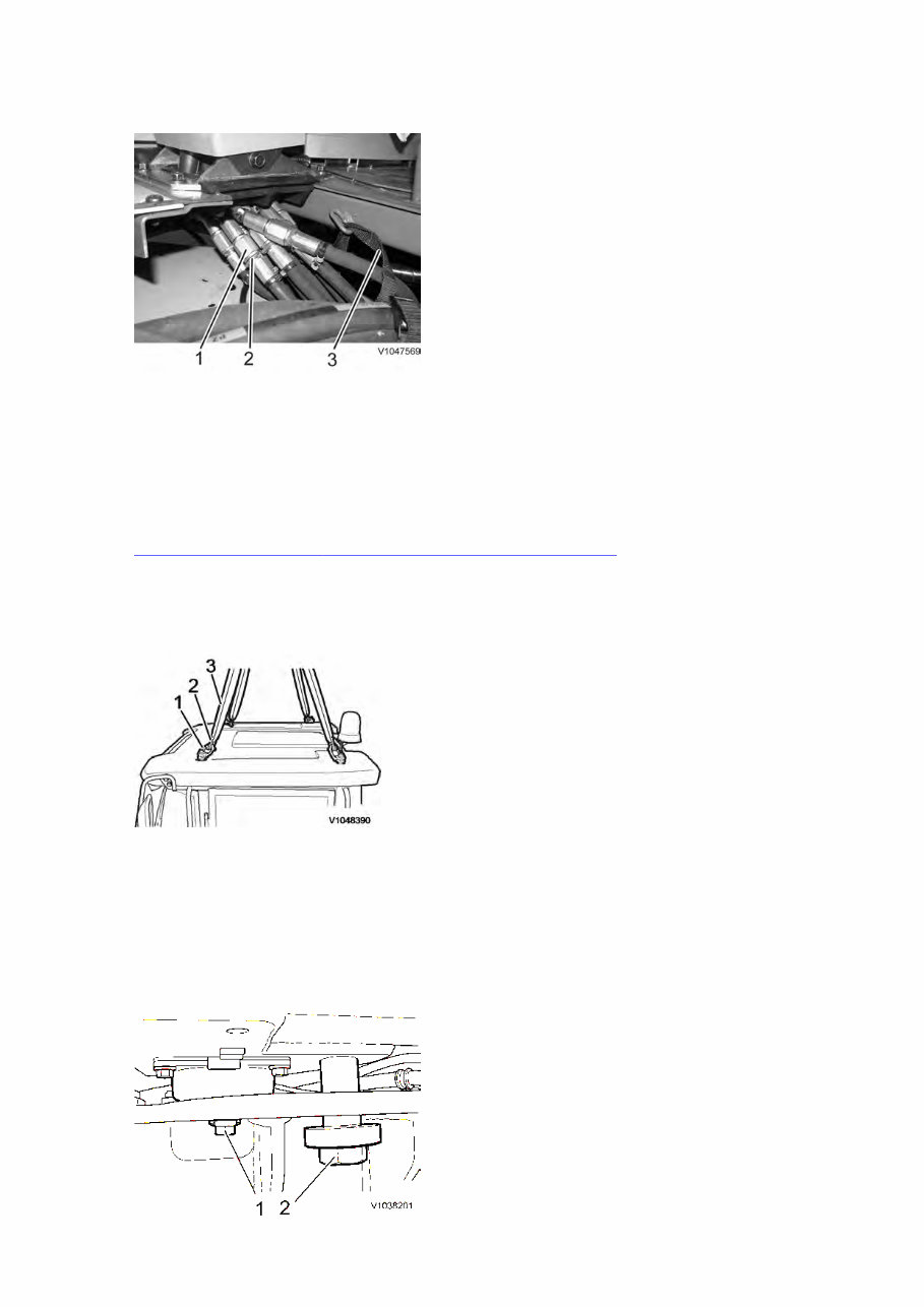
19. Remove the four bolts that hold the outer roof.
Connect the lifting device as shown.
Figure 11
1.
2.
3.
Lifting eye M16, 4 pcs.
Shackle, 4 pcs
Sling, 2 pcs.
20. Remove the top step on the left side of the machine.
Remove the cab's attaching bolts and safety bolts.

Figure 12
1.
2.
Attaching bolt
Safety bolt
21. Lift away the cab. Weight approx. 800 kg (1764 lbs).
22. Re-install the step and secure with two bolts.
[ 1]Optional equipment
[ 2]Optional equipment
[ 3]Optional equipment
Service Information
Document Title: Function Group: Information Type: Date:
Cab, removing 810 Service Information 2014/5/8 0
Profile:
WLO, L120F [GB]
Go back to Index Page
Cab, removing
Op nbr 810-001
14360000 Vacuum pump / 24V
88830070 Plug
88830070 Plug
88830070 Plug
88830070 Plug
88830070 Plug
88830070 Plug
88830070 Plug
88830070 Plug
88830070 Plug
88830070 Plug
Sling 4 m (13 ft), 2 pcs
Lifting eye M16, 4 pcs
Shackle, 4 pcs
Hose pliers, 4 pcs
NOTE!
Do not loosen any hoses or connections for the air conditioning and thereby inadvertently releasing refrigerant.
1. Place the machine in service position 1, see .
191 Service position
2. Remove the front part of the rear mudguard on the right and left sides of the machine. Weight approx. 35 kg (80
lb).
Remove the cover plate behind the front part of the rear mudguard on the right side of the machine.
Figure 1
1. Front part of rear mudguard
3. Part the washer fluid hoses at the non-return valves.
Figure 2
1. Connectors, washer fluid
4. Remove the plastic casing together with the air filters.
Remove the plate and detach the connector for the recirculation damper, MO8703.
Figure 3
1. Connector
5. Part the connector for the pressure monitor, SE8709, and cut the ties.
Pull the hose out of the cab temperature sensor.
Remove the sealing strip and the guard plate.
Loosen the bolt for the clamp.
Push out the plastics on the right side of the evaporator so that the lug on the evaporator is exposed. Swing out
the attaching plate together with the evaporator and place it on the step.
You're Reading a Preview
What's Included?
Fast Download Speeds
Offline Viewing
Access Contents & Bookmarks
Full Search Facility
Print one or all pages of your manual
$39.99
Viewed 19 Times Today


Secure transaction
What's Included?
Fast Download Speeds
Offline Viewing
Access Contents & Bookmarks
Full Search Facility
Print one or all pages of your manual
$39.99
- This is a comprehensive Factory Service Repair Workshop Manual for the Volvo L120F Wheel Loader.
- It is available for instant access on your computer, tablet, or smartphone.
- The manual covers all repairs, servicing, and troubleshooting procedures with detailed photos and diagrams.
- Professional mechanics and technicians use this manual, which includes step-by-step instructions and highly detailed exploded diagrams and pictures.
- Yes, you can print out a single page or the entire manual as per your preference.
- This manual can be used on multiple computers without any limitations or trial periods.
- There is no expiry date or renewal fee for this full manual, and it can be used for life.
- It is fully compatible with Windows and MAC computers.
For more information, please click on the button.


