

Volvo BM L90C Wheel Loader Service Manual
What's Included?
Fast Download Speeds
Offline Viewing
Access Contents & Bookmarks
Full Search Facility
Print one or all pages of your manual
Service Information
Document Title: Function Group: Information Type: Date:
Cab, installing 810 Service Information 2014/5/27
Profile:
Cab, installing
Op nbr 81002
Sling, 2 m (6 ft), 2 pcs
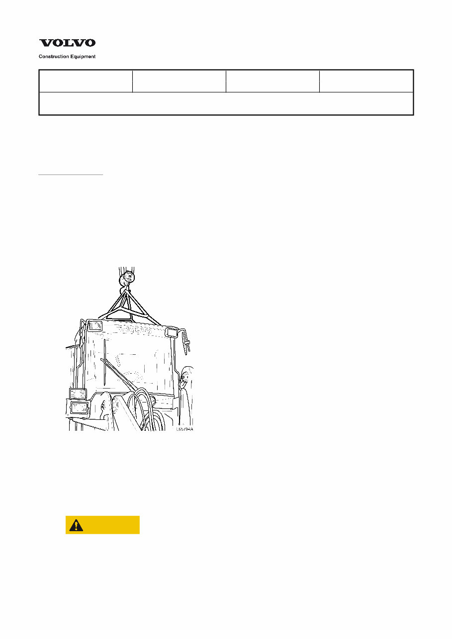
1. Connect the slings to the handholds on the cab.
2. Check that the rubber elements are serviceable. Position a washer on each element.
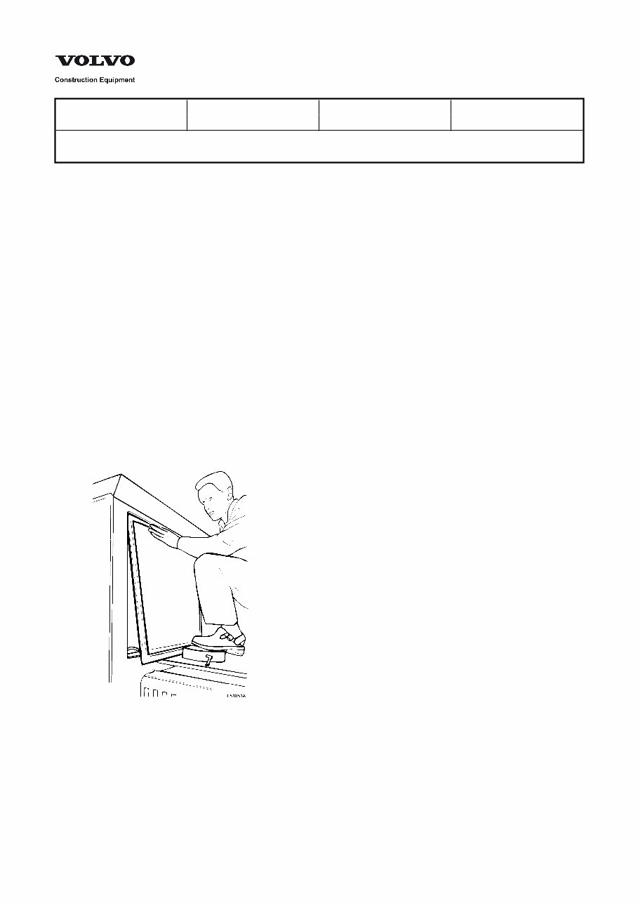
3. Lift the cab into position.
Cab weight: approx. 700 kg (1543 lb)
Install the lower rubber elements and the bolts together with washers.
Figure 1
Installing cab
4. Remove the lifting device.
5. Connect the coolant hoses to the cab radiator.
6. Secure the evaporator to the climate control unit.
CAUTION
Do not disconnect the hoses from the evaporator, as it contains refrigerant under pressure.
7. Install the servo valve on the bracket and secure it.
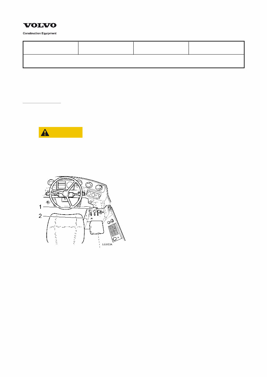
8. Instal the plastic casing on the side of the control lever carrier.

Figure 2
1.
2.
Casing over control levers
Casing on side of control lever carrier
9. Install the casing over the control levers.
10. Connect all cable harnesses to the electrical distribution box according to the markings on the connectors and on
the electrical distribution box.
11. Install the engine heater and connect the reversing light cable.
12. Install the foot brake valve.
13. Connect the hoses to the steering valve.
14. Connect the control cable to the accelerator pedal.
15. Install the centre floor plate.
16. Put back the floor mat.
17. Install the brake pedal.
Service Information
Document Title: Function Group: Information Type: Date:
Cab, removing 810 Service Information 2014/5/27
Profile:
Cab, removing
Op nbr 81001
Sling, 2 m (6 ft), 2 pcs
1. Detach the evaporator (AC) from the cab and lay it in a protected position on the steps.
CAUTION
Do not disconnect the hoses from the evaporator, as it contains refrigerant under pressure.
2. Disconnect the coolant hoses from the cab radiator.
NOTE!
Use pairs of hose pliers or alternatively drain the coolant.
3. Remove the casing over the control levers.
Figure 1
1.
2.
Casing over control levers
Casing on side of control lever carrier
4. Remove the plastic casing on the side of the control lever carrier.
5. Disconnect the cables from the control lever carrier.
6. Remove the brake pedal.
7. Remove the floor mat.
8. Remove the centre floor plate.
9. Detach the servo valve (four bolts) and lay down the servo valve together with hoses and levers through the hole in
the floor.
10. Detach the foot brake valve from the floor.
11. Disconnect the hoses from the steering valve.
12. Disconnect the control cable from the accelerator pedal.
13. Disconnect the connectors on the cable harnesses from the electrical distribution box and pull them out through
the lead-through in the cab wall. Mark the respective holes and cable harnesses, so that they can be installed in the
same holes when assembling.
The connectors are moved through the plastic nuts.
14. Remove the four attaching bolts, washers and lower rubber spacer securing the cab.
15. Disconnect the engine heater connection and the cable for the reversing lights.
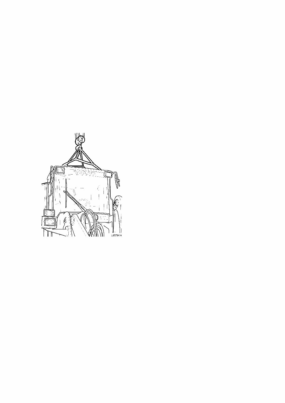
16. Connect the slings to the handholds on the cab.
17. Lifting the cab.
Cab weight: approx. 700 kg (1543 lb)
Figure 2
Removing cab

Service Information
Document Title: Function Group: Information Type: Date:
Description 843 Service Information 2014/5/27
Profile:
Description
The windscreen on the cab is divided into three panes with silicone-sealed joints. To fix the position of the windscreen there
are four clips at the upper edge.
Service Information
Document Title: Function Group: Information Type: Date:
Rear window,
sealing
843 Service Information 2014/5/27
Profile:
Rear window, sealing
Op nbr
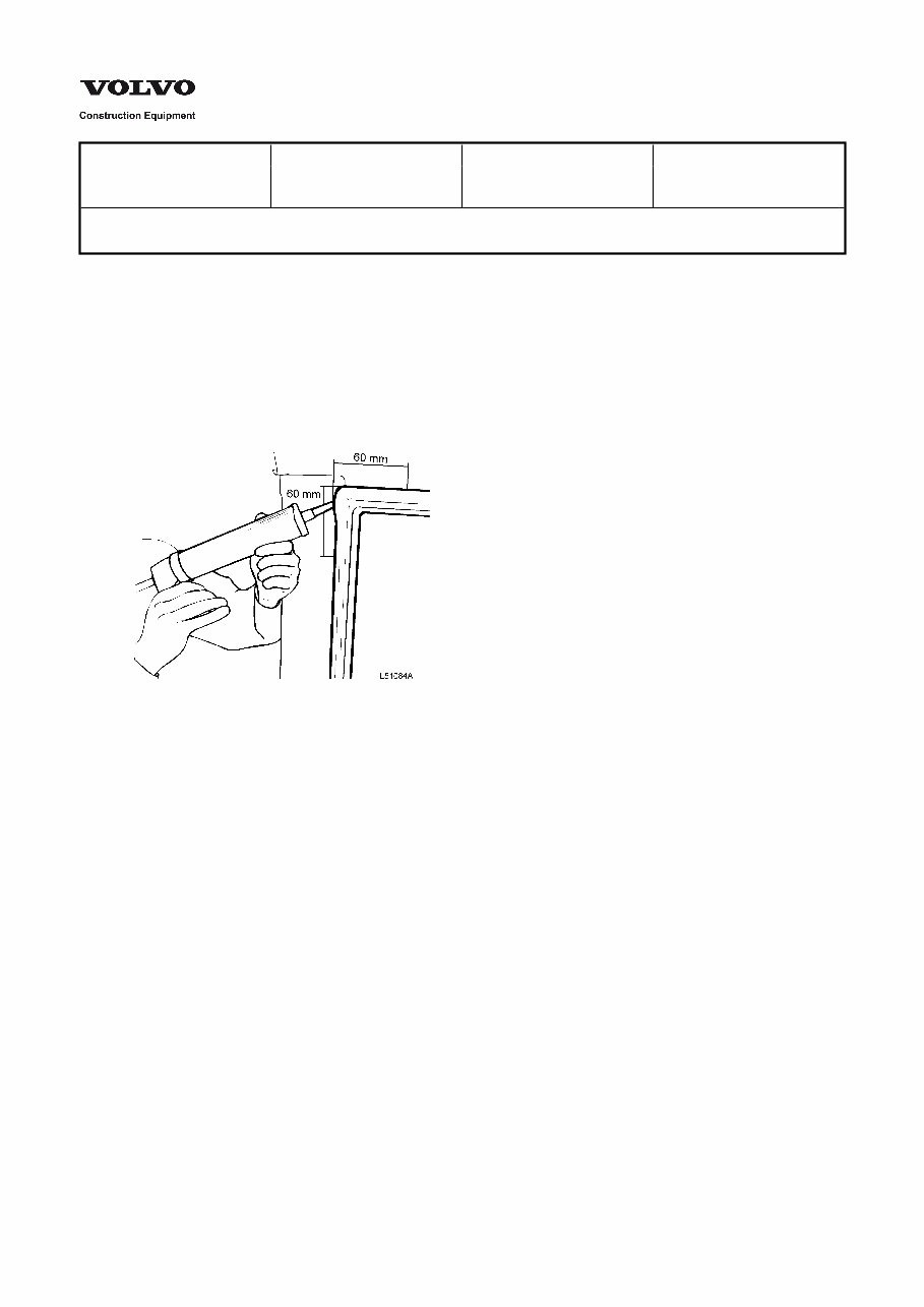
1. Inject sealant (part No. 11998258-5) at the upper corners between the rubber moulding and attaching edge, over a
distance of approx. 60 + 60 mm (2.4 + 2.4 in).
Figure 1
2. Inject sealant, over a distance of approx. 60 mm (2.4 in) at the lower corners.
Service Information
Document Title: Function Group: Information Type: Date:
Rear window, replacing 843 Service Information 2014/5/27
Profile:
Rear window, replacing
Op nbr
Removing
1. Remove the wall lining at the rear and the rear window wiper motor.
2. Push out the window pane and the moulding at one corner and press the rubber moulding over the attaching edge
and remove the window pane.
Installing
3. Install the rubber moulding on the window pane. Place a pulling cord (for example an electrical lead) in the fold for
the attaching edge in the rubber moulding at the lower part of the pane and a little way up past the corner.
4. Lubricate the attaching edge in the cab with a soap solution or similar.
Push up the window pane so that the moulding at the upper part of the pane is placed around the attaching edge
of the cab.
Figure 1
5. Press in the lower part of the pane and pull at the cord so that the moulding grips around the attaching edge, see
[Invalid linktarget] and [Invalid linktarget] .
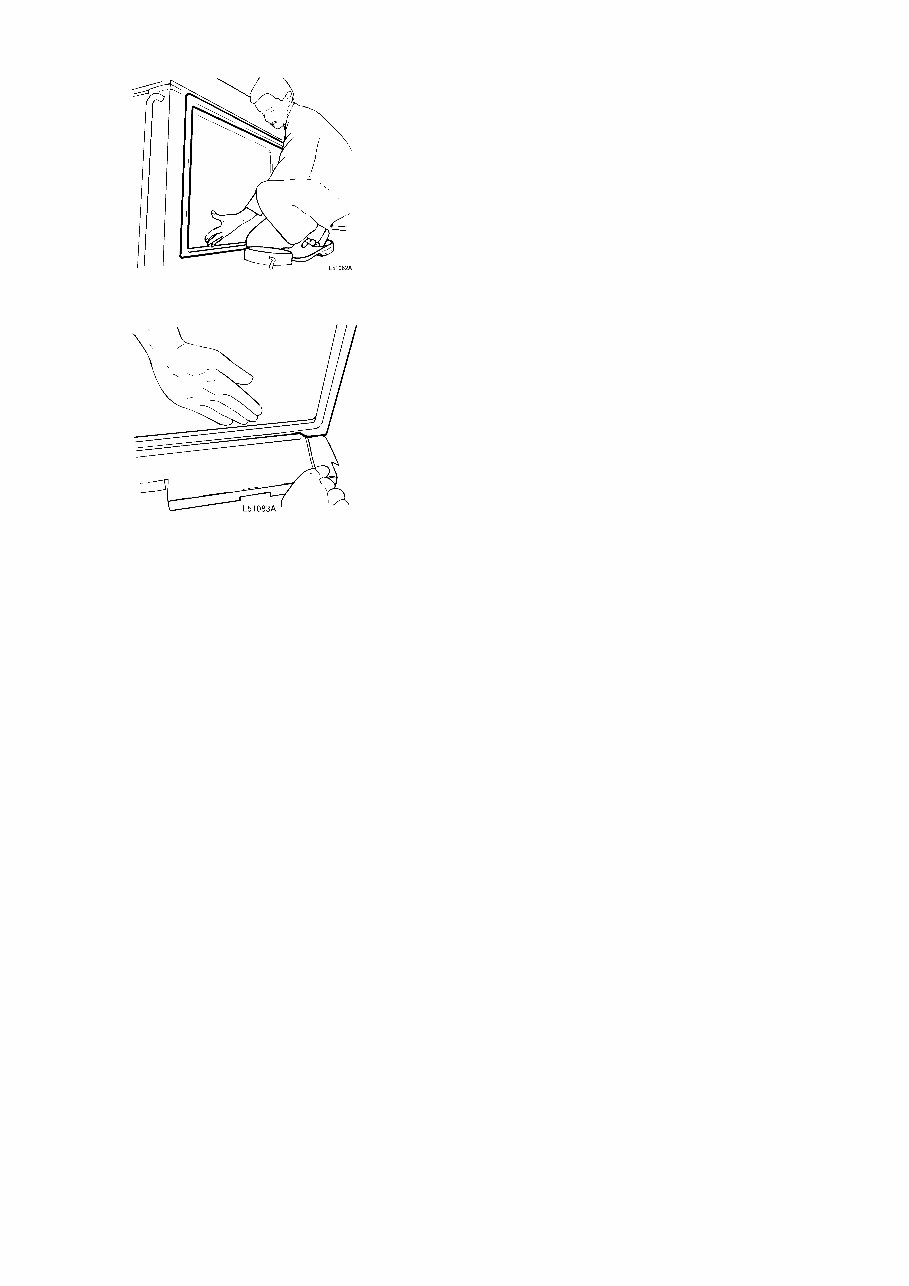
Figure 2
Figure 3
6. Seal the rear window, see [Invalid linktarget] .
Service Information
Document Title: Function Group: Information Type: Date:
Windscreen side pane,
replacing
and sealing
843 Service Information 2014/5/27
Profile:
Windscreen side pane, replacing and sealing
Op nbr
Removing
1. Remove the working lights and the overhead panel from the front edge of the cab roof.
2. Remove the clips from the upper edge of the window pane.
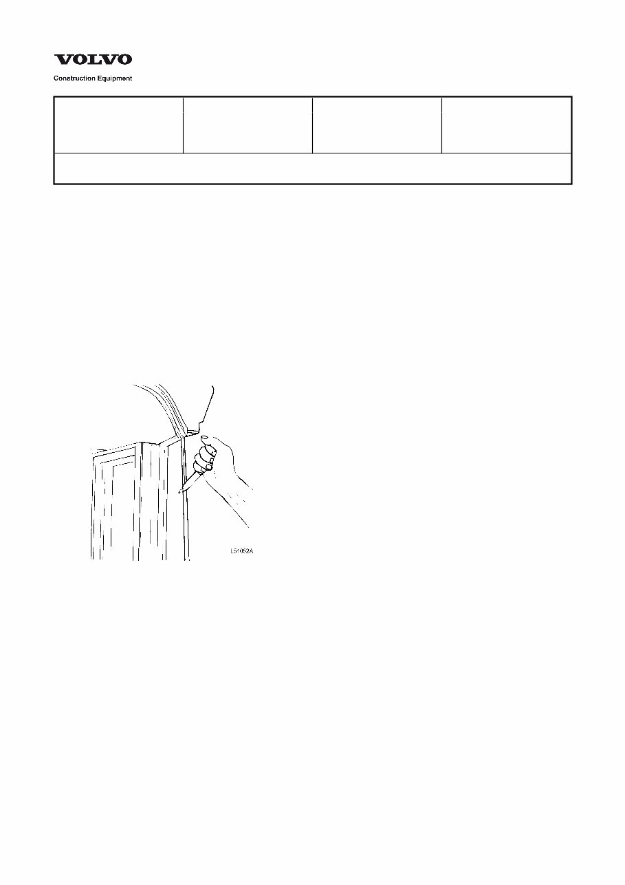
3. Cut off the joints between windscreen and the side panes with a thin knife or similar.
Figure 1
4. Prize out the side pane and the rubber moulding at the rear edge away from the cab post, see [Invalid linktarget]
and [Invalid linktarget] .
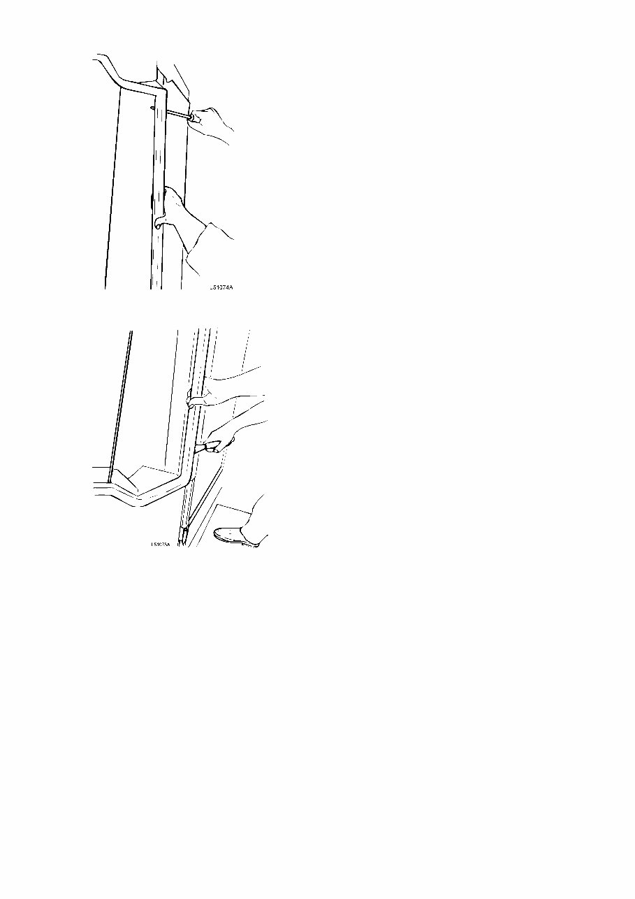
Figure 2
Figure 3
5. Fold the rubber moulding over the edge and remove the side pane.
Installing
6. Clean off any silicon sealant residue from the edge of the windscreen.
Wash with spirit.
7. Lengths of butyl tape should be placed on the side member in the radius (corner) between the plate edge and the
member from the upper to the lower corner, see measurement A in [Invalid linktarget] .
You're Reading a Preview
What's Included?
Fast Download Speeds
Offline Viewing
Access Contents & Bookmarks
Full Search Facility
Print one or all pages of your manual
$42.99
Viewed 30 Times Today


Secure transaction
What's Included?
Fast Download Speeds
Offline Viewing
Access Contents & Bookmarks
Full Search Facility
Print one or all pages of your manual
$42.99
This manual contains maintenance and repair procedures for the Volvo BM L90C Wheel Loader.
- Volvo BM L90C Wheel Loader Service Repair Factory Manual is an electronic version of the best original maintenance manual. Compared to the electronic version and paper version, there is a great advantage. It can zoom in anywhere on your computer, so you can see it clearly. Your Volvo BM L90C Wheel Loader parts correspond with the number of pages printed on it in this manual, very easy to use.
- Volvo BM L90C Wheel Loader Service Repair Factory Manual is a perfect manual, which contains a lot of information. It covers the following models:
Volvo BM L90C Wheel Loader Service Repair Factory Manual
- General Information
- Specifications
- Technical Features and Description
- Rigging Information
- Troubleshooting
- Electrical System
- Fuel System
- Power Unit
- Lower Unit
- Bracket Unit
- Maintenance
- Index
- Appendix
- ... and more
Volvo BM L90C Wheel Loader Service Repair Factory Manual is written step by step in details, so you become very easy to repair by yourself. It can save your expenses. Do not hesitate, after your payment, you will immediately get the manual.
File Format:
- Compatible: All Versions of Windows & Mac
- Language: English
- Requirements: Adobe Reader


