VOLVO BM L50 Wheel Loader Service and Repair Manual
What's Included?
Lifetime Access
Fast Download Speeds
Online & Offline Access
Access PDF Contents & Bookmarks
Full Search Facility
Print one or all pages of your manual
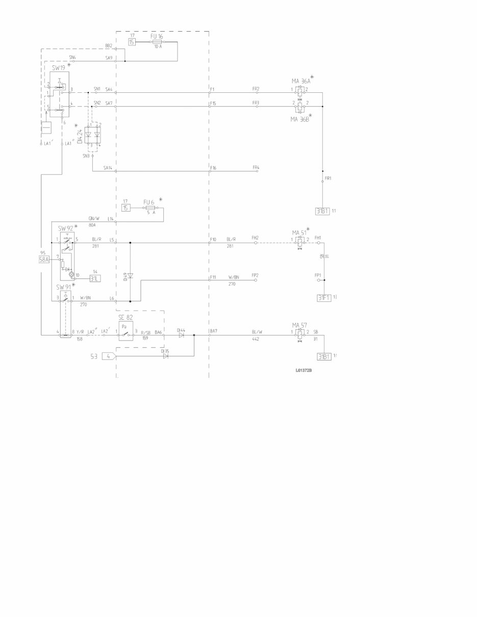
4th hydraulic function, description In addition to the ordinary control valve the L50C can be equipped with an electrically controlled solenoid valve (MA36A) for operating the 4th hydraulic function, the quick-action couplings of which are mounted at the very end of the lifting arms. The oil flow is controlled with a spring-return switch (SW19) positioned on the control lever carrier casing for the ordinary lifting functions and it is either switched on or off. The 4th hydraulic function is double-acting and the flow can be switched between the right and the left side. The function is intended to be used for controlling hydraulic cylinders such as an angle plow and a catch arm. Continuous flow via the 4th hydraulic function is not permissible. The 4th hydraulic function is supplied by the ordinary hydraulic pumps and the oil to the solenoid valve is taken through the pressure port of the ordinary control valve. Depending on whether it is an early or late version, the oil pressure for the activated function is 16.5 ±1.0 MPa (2393 ±73 psi) and 21.0 ±1.0 MPa (3046 ±145) respectively with a maximum flow of 30 litres (7.9 US gal) per minute. This applies when the 4th function is the only hydraulic function which is activated. If the control hydraulics is activated at the same time, the input pressure to the solenoid valve may amount to at the most 26.0 MPa (3771 psi), but the output pressure is limited by a pressure reducing valve to 21.0 ±1.0 MPa (3046 ±145 psi). Description of function L50C s/n –10852 (earlier type) When switch SW19 is operated, MA36A or MA36B is energised, depending on which end of the switch that has been pressed down. At the same time MA85 is energised and provides the hydraulic pumps with LS-signal. (LS = Load Sensing). The pressure-limiting valve under MA36A/B limits the output pressure to 21 ±1.0 MPa (3046 ±145 psi). By operating SW19 the current to the solenoid valve MA57 for brake charging is interrupted, which means that the brake charging is initiated. Thereby increasing the oil flow. Pressure draining of quick-action couplings is carried out by operating SW91 so that current is supplied to MA48. MA48 opens and drains the oil at the quick-action couplings to tank. L50C s/n 10853– (later type) When switch SW19 is operated, MA36A or MA36B is energised, depending on which end of the switch that has been pressed down. At the same time the current to the solenoid valve for brake charging MA57 is interrupted, which means that the brake charging is initiated. The resulting pressure amounts to 16.5 ±1.0 MPa (2393 ±145 psi) as the brake charging LS-signal is limited with a pressure-reducing valve positioned under MA57 on the central valve. If another hydraulic function is operated at the same time as 4th function, the pressure in the hydraulic system may increase to at the most 26.0 ±3.5 MPa (3771 ±508 psi). The output pressure is then limited by the pressure-reducing valve under MA36A/B to at the most 21.0 ±1.0 MPa (3046 ±145 psi). With the engine turned off and the ignition switch in position 1, it is possible to drain the quick-action couplings by repeatedly operating SW19, which then supplies current to MA36A/B which in turn opens and lets the pressure out to the tank.
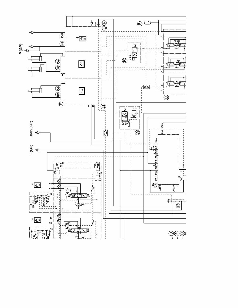
5th/6th hydraulic functions and attachment Figure 1 Hydraulic diagram, 5th/6th hydraulic functions and attachment hydraulics GP
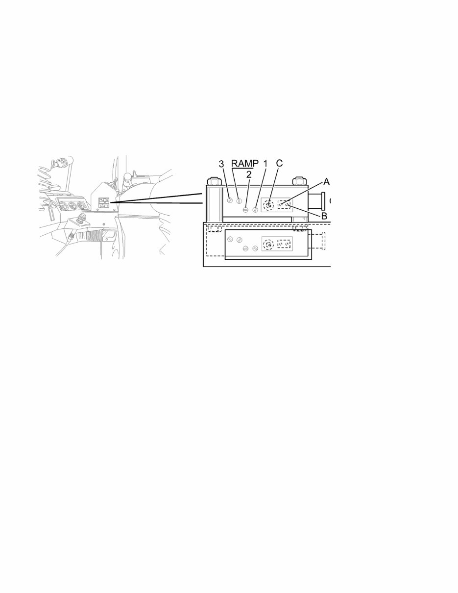
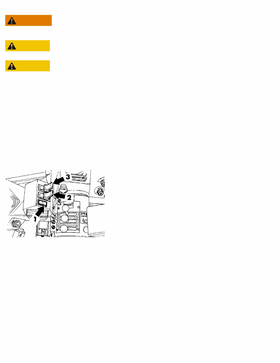
5th/6th hydraulic functions, adjusting speed/flow Op nbr 516 Introduction Working method for adjustment by checking current and voltage: see 5th/6th hydraulic functions, basic adjustment of speed/flow Before any adjustments are carried out, the machine, particularly the working hydraulics, must have been operated until it is warm. For adjustment of the speed of the respective functions there are three potentiometers (trimming potentiometers) on each control unit, see Fig. 64. NOTE! To gain access to the control units; remove the panel on which the controls for 5th/6th hydraulic functions are positioned! Figure 1 Trimming potentiometers, position 1. 2. 3. Adjusting starting speed, which is the same in both directions Adjusting final speed, which is the same in both directions Fine adjustment of the final speed, lever forward 1. RAMP Adjusting the ramp function, i.e. the damping of the control signal to obtain a smooth retardation of the hydraulic cylinder movement when the lever is moved from maximum deflection to neutral. Adjusting starting speed As this adjustment covers both directions, the adjustment should be carried out for the direction in which the lever is most sensitive. 1. 2. 3. 4. 5. Start the engine. Operate the lowering function of the standard hydraulics against its end position. Keep the lowering lever in this position during the entire adjustment of the starting speed. (So that maximum working pressure is obtained.) Carefully move the lever for the 5th (6th) function forward or rearward, so that it leaves the neutral position. Screw on trimming potentiometer 1 until the movement of the hydraulic cylinder just starts or stops. Turn trimming potentiometer 1 and a 1/2 turn counter-clockwise. Adjusting final speed 1. 2. 3. Move the lever for the 5th (6th) hydraulic function fully forward. Turn trimming potentiometer 2 clockwise until the movement of the hydraulic cylinder has reached its maximum speed (or counter-clockwise until the free travel at the end of the lever deflection disappears). With both these alternatives the maximum speed is affected in both directions. Using trimming potentiometer 3, adjust, if necessary, the difference in speed (the symmetry) between the piston side and the piston rod side so that the correct maximum speed of the cylinder movement in both directions is obtained. Adjusting RAMP Adjusting 1. To increase damping: turn trimming potentiometer RAMP clockwise.
2. To reduce damping: turn trimming potentiometer RAMP counter-clockwise.
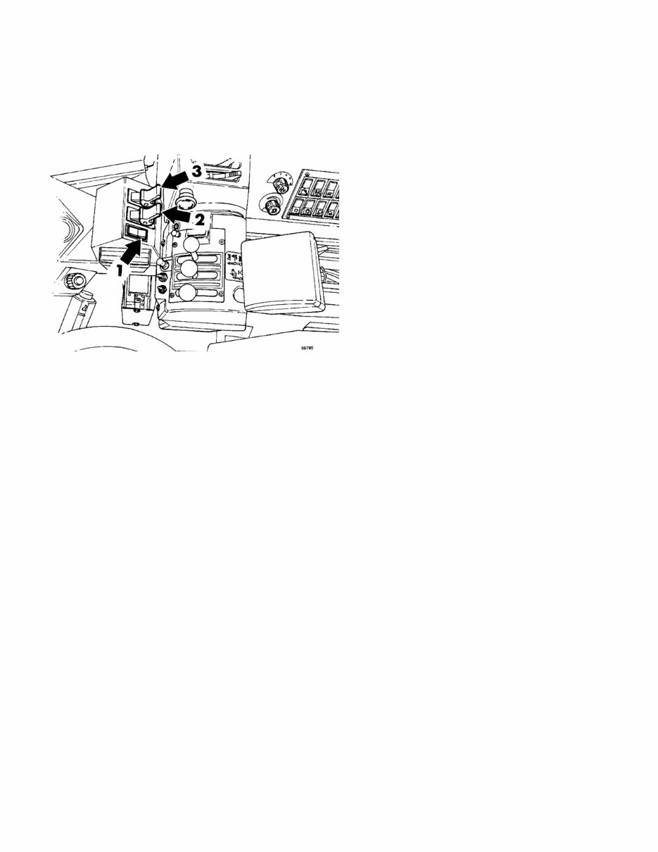
5th/6th hydraulic functions, basic adjustment of speed/flow Op nbr 516 Voltmeter Ammeter This working method includes basic setting of linear levers CU16 (6th hydraulic function) and CU18 (5th hydraulic function) and control units CU15 (6th hydraulic function) and CU17 (5th hydraulic function). SeeFig. 65 Basic adjustment The following applies when checking: Voltage between pins A and B on CU17 and CU15 respectively 0 10 mV Current through HK5 and HK6, starting position Max. 0.3 A Flow (speed) 0.4 A Max. lever movement (symmetrically) 0.4 A RAMP (damping) 1.0 second 1. 2. 3. Connect a voltmeter to pins A and B on CU17 and CU15 respectively. See Fig. 65. Figure 1 Trimming potentiometers, position 1. 2. 3. Adjusting starting speed, which is the same in both directions Adjusting final speed, which is the same in both directions Fine adjustment of the final speed, lever forward Switch on switch SW125 and, using screw C (under the tape), adjust the voltage between A and B to 0 10 mV. NOTE! Take care not to cause short circuits with the metal plate parts on the control units. Connect an ammeter at connectors HK5 and HK6, and HK 1 and HK2 respectively, (positioned under the mat by the parking brake, see Fig. 66).
4. 5. 6. 7. 8. Figure 2 Connector HK, position Adjust the starting speed using screw 1 to at the most 0.3 A. Check the current at connector HK5 and HK6, and HK 1 and HK2 respectively, moving the lever in both directions. Adjust the flow (the speed) to 0.4 A using screw 2 (lever forward). Using screw 3, adjust the symmetry between the piston side and the piston rod side to 0.4 A with the lever fully rearward. Adjust the RAMP (the damping) to max. 1.0 second using screw marked RAMP.
5th/6th hydraulic functions, description WARNING The connection of an hydraulic motor to the hydraulic outlets is not permitted, as charging of the brake system would then not work. CAUTION 5th, 6th and 7th (National Road Administration version) hydraulic functions are only intended for use with hydraulic cylinders. CAUTION Valve banks on attachments must not be supplied from the 5th, 6th or 7th hydraulic functions with oil which is pumped round in the system. 5th, 6th and 7th hydraulic functions are available for the L50C as optional equipment. Here follows a description of this equipment. The control valve for 5th, 6th and 7th hydraulic functions, which is proportionally controlled, is supplied from the ordinary hydraulic pumps and can thus also be installed in machines without attachment hydraulics GP. The control valve is load-sensing (LS) and is of the "closed centre" type. There is a possibility for individual adjustment of the sensitivity of the control levers. The oil enters the valve before the ordinary control valve. The maximum working pressure of the incoming oil is 26.0 MPa (3771 psi) for the 5th and 6th functions and 16.5 MPa (2393 psi) for the 7th function. The maximum output pressure from the valve is 21.0 0.5 MPa (3047 73 psi). The maximum output flow is 70 litres (18.5 US gal) per minute. (50-60 litres (13.2-15.8 US gal) per minute is set at the factory). The hydraulic outlets (double-acting and routed out to the same brackets as the hydraulic outlets for attachment hydraulics GP) are provided with male couplings TEMA 1/2”. The 5th and 6th hydraulic functions are operated with two control levers in the cab, Fig. 55. Figure 1 Position of controls for 5th and 6th hydraulic functions 1. 2. 3. Activation of 5th and 6th hydraulic functions, SW125 Control lever 6th hydraulic function, CU16 Control lever 5th hydraulic function, CU18 On the carrier for the control levers there is also a switch (item 1, Fig. 55) for activating and deactivating the 5th/6th hydraulic functions. Adjusting possibilities The starting and final speeds of the hydraulic cylinders can be adjusted in two alternative ways. Partly with the aid of electrical measuring, see “, page 9:64”, and partly through a visual check, see , page 9:67. These sections also describe how the RAMP function is adjusted. By the designation RAMP is here meant the damping of the control signal which takes place when the control lever for the hydraulic function is moved from maximum deflection to neutral. The damping is necessary to obtain a smooth retardation of the cylinder movement before it is stopped fully. If the lever is moved past the neutral position, no damping is obtained. The damping is adjustable between 0 seconds and 2 seconds. See also “5th and 6th hydraulic functions, electrical functions”.
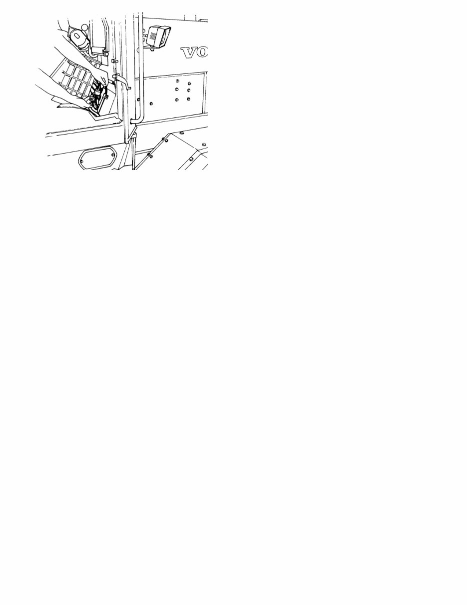
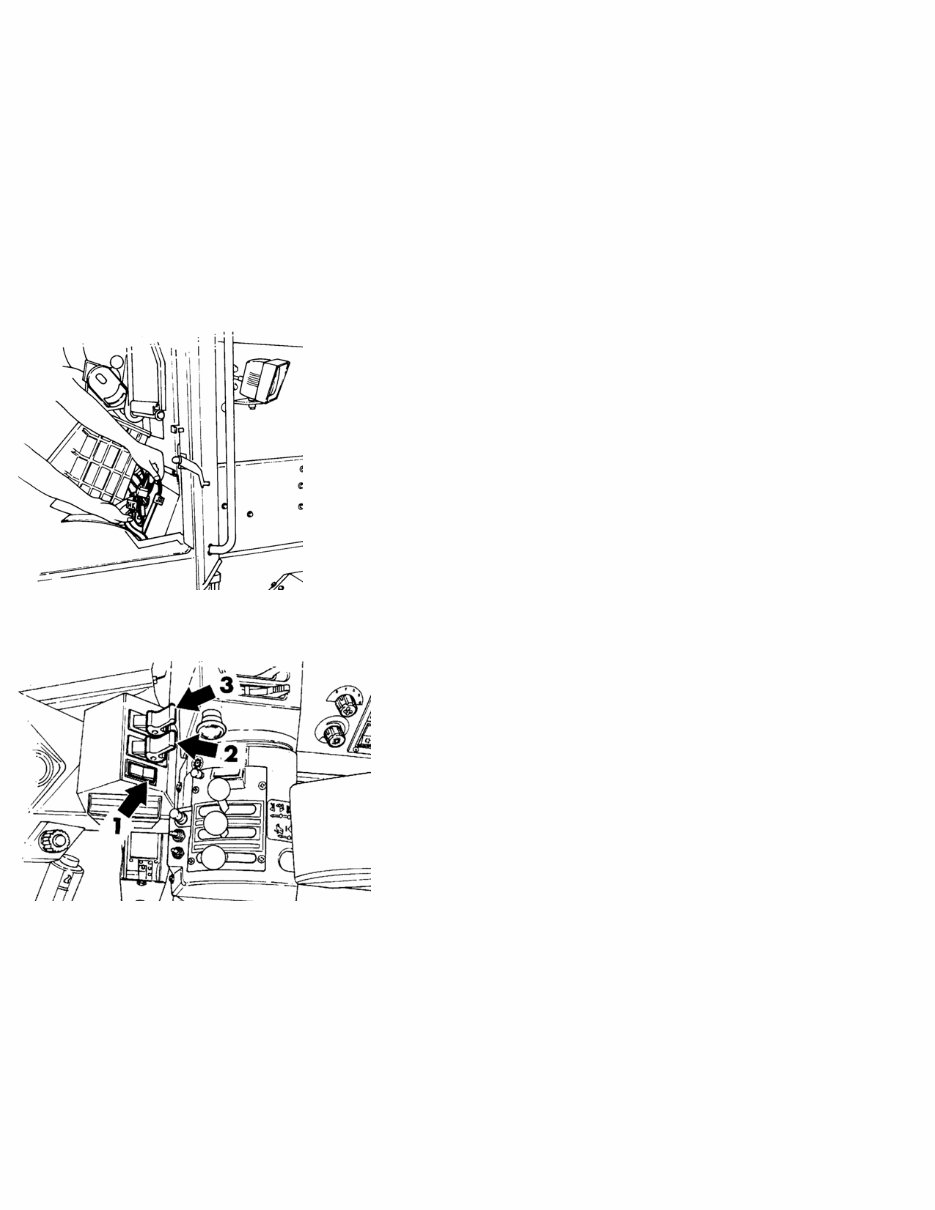
5th/6th hydraulic functions, draining the quick-action couplings The quick-action couplings can be drained to facilitate connecting attachments as follows: 1. 2. Turn the ignition key to running position (position 1) and activate 5th and 6th hydraulic functions with switch SW125. NOTE! The engine must not be started! Then move the control levers for the 5th (CU18) and the 6th (CU16) hydraulic functions to and fro a few times (draining is possible as the machine has an accumulator for servo pressure, see hydraulic diagram). The accumulator is positioned on the right side under the cab. Figure 1 5th and 6th hydraulic functions, operating control position 1. 2. 3. Activating 5th and 6th hydraulic functions Control lever, 6th hydraulic function Control lever, 5th hydraulic function If a sufficient draining is not obtained, the engine should be started and run at idling speed until the accumulator has been charged. Then stop the engine. Then repeat points 1 and 2 above.
5th/6th hydraulic functions, electrical functions. What is said below about the 5th hydraulic function also applies to the 6th function. RE26 receives continuous battery voltage at connection 30. When the ignition key is turned to running position, i.e. position 1, voltage will also be available at connection 86 and RE26 will be activated. Via FU61 the activated RE26 now supplies voltage to: connection 2 on SW125 connection 30 on RE35 RE35 now becomes self-holding and remains activated, in that the current passes across connections 30 - 87 and further on to connection 86, even when SW125 is switched off.When SW125 is switched on, current is supplied to RE35, connection 86, which is activated, and to connection HN3 on CU17, see Fig. 59. CU18 controls CU17 via connector HO and, depending on the signal from CU18, CU17 supplies current to solenoid valves MA132 or MA133 on the control valve. MA132 is supplied from connection HN1 via connector HK5. MA133 is supplied from HN2 via connector HK6. Figure 1 Position of connector HK Figure 2 Position of controls for 5th and 6th hydraulic functions 1. 2. 3. Activation of 5th and 6th hydraulic functions, SW125 Control lever 6th hydraulic function, CU16 Control lever 5th hydraulic function, CU18 In the linear lever CU18 there is a microswitch for centre position indication and a non-contacting inductive sensor for the lever position. The output terminals HN1 and HN2 on CU17 are current controlled, so called pulse width modulated (PWM), which means that they supply the correct current regardless of supply voltage and resistance changes in the circuits leading to MA132 and MA133. The output current is pulsating direct current with a frequency of 125 Hz. The PWM output terminals have adjustable preoscillation and postoscillation currents. The preoscillation current is the same for each output terminal whereas the postoscillation current is individual for each output terminal.
When it comes to repairing your VOLVO BM L50 WHEEL LOADER, having the right manual is crucial. Our VOLVO CONSTRUCTION Repair Manuals provide comprehensive instructions and procedures for fixing vehicle/truck problems. Whether you're a professional mechanic or a DIY enthusiast, these manuals can be invaluable for immediate repairs and routine maintenance.
Each repair manual contains technical data, diagrams, a complete list of parts, and illustrations to guide you through the repair process. Even novice construction mechanics can easily follow the step-by-step guides and benefit from the included pictures and illustrations.
These manuals cover a wide range of sections and include hundreds of photos, making them essential for maintaining and repairing your VOLVO BM L50 WHEEL LOADER. Whether it's articulated haulers, backhoe loaders, compact excavators, asphalt compactors, soil compactors, compact wheel loaders, excavators, motor graders, tracked pavers, wheeled pavers, pipelayers, road wideners, screeds, skid steer loaders, or wheel loaders, our manuals have you covered.
Our repair manuals are available in .PDF format and .OVA file format, providing compatibility with Windows Vista32 and 64, XP, ME, 98, NT, 2000, and Mac operating systems. You can easily print the pages and diagrams you need, ensuring that you have the necessary information at your fingertips, whether you're in the workshop or working on your vehicle/truck.
The manuals cover a wide range of topics, including maintenance, engine, control system, mechanical, fuel service specifications, emission control, and much more. They are designed to provide you with everything you need to service and repair your vehicle/truck with ease.
With our repair manuals, you can save time and gain a deeper understanding of your vehicle/truck. You'll no longer have to rely solely on your mechanic for repairs, as you can now perform them in the comfort of your garage. The printable pages ensure that you can easily reference the information you need without worrying about damaging physical manuals.
For comprehensive, vehicle-specific repair information, our VOLVO CONSTRUCTION Repair Manuals are the ideal choice. They are your go-to resource for maintaining, servicing, diagnosing, and repairing your VOLVO BM L50 WHEEL LOADER.
Recently Viewed
5,521,897Happy Clients
2,594,462eManuals
1,120,453Trusted Sellers
15Years in Business
Price:
Actual Price:
VOLVO BM L50 Wheel Loader Service and Repair Manual