

Komatsu WA50-3 workshop manual.
What's Included?
Fast Download Speeds
Online & Offline Access
Access PDF Contents & Bookmarks
Full Search Facility
Print one or all pages of your manual

00-1
• This shop manual may contain attachments and optional equipment that are not avail-
able in your area. Please consult your local Komatsu distributor for those items you may
require. Materials and specifications are subject to change without notice.
• WA50-3 mount the S3D84E-3B and S3D84E-5X engine.
For details of the engine, see the 68E-88E Series Engine Shop Manual.
-
© 2004 1
All Rights Reserved
Printed in Japan 03-04(03)00001
1
MACHINE MODEL SERIAL NUMBER
WA50-3 21450 and up
SEBM017803
(3)
CONTENTS
No. of page
01 GENERAL
. ... . . . .. . ... . . . .. .. .. . ... .. . .. ... .. . . . . .. . .. .. .. .. . . . . . ... ... ..*........
01-l
10 STRUCTURE AND FUNCTION
. . .. . .. . . . . .. . .. .. . . . . ... . .. . . ..a......
IO-I
20 TESTING AND ADJUSTING
... .. . .. .. .. . . . .. . .. .. . . . .. .. . .. . . ... . .. . . .
20-I
30 DISASSEMBLY AND ASSEMBLY
. .. .. . . . ... ...m...................
30-I
40 MAINTENANCE STANDARD
,,...,...*..............................*.
40-I
90 OTHERS
. .. .. .. . .. ...*..............................................................
90-l
WA50-3
The affected pages are indicated by the use of the
following marks. It is requested that necessary actions
must be taken to these pages according to the list
below.
Pages having no marks are not revised at this time.
LIST OF REVISED PAGES
Revision
Mark Pages
number
Revision
Mark Pages
number
Revision
Mark Pages
number
Revision
Mark Pages
number
Revision
Mark Pages
number
‡ 00- 1 (3)
00- 2 (1)
‡ 00- 2-1 (3)
‡ 00- 2-2 (3)
‡ 00- 3
‡ 00- 4
‡ 00- 5
‡ 00- 6
‡ 00- 7
‡ 00- 8
‡ 00- 9
‡ 00-10
‡ 00-11
‡ 00-12
‡ 00-13
‡ 00-14
‡ 00-15
‡ 00-16
‡ 00-17
‡ 00-18
‡ 00-19
‡ 00-20
‡ 00-21
‡ 00-22
01- 1 (1)
01- 2
01- 3 (1)
01- 4 (2)
01- 5 (2)
01- 6 (1)
01- 7 (2)
01- 8 (2)
01- 9 (2)
10- 1 (1)
10- 3
10- 4
10- 5 (1)
10- 6 (2)
10- 6-1 (2)
10- 7 (1)
10- 8 (2)
10- 8-1 (2)
10- 9 (2)
10-10 (2)
10-11 (2)
10-12 (2)
10-13
10-14 (1)
10-15 (2)
10-16 (2)
10-17 (2)
10-18 (2)
10-19 (2)
10-20 (2)
10-21
10-22
10-23 (2)
10-23-1 (2)
10-24 (2)
10-25
10-26 (2)
10-27
10-28
10-29
10-30
10-31
10-32
10-33
10-34
10-35 (2)
10-36 (2)
10-37 (2)
10-38 (2)
10-39 (2)
10-40 (2)
10-41
10-42 (2)
10-43 (2)
10-44 (2)
10-45
10-46
10-47
10-48
10-49 (2)
10-50 (1)
10-52 (1)
10-53 (1)
10-54 (1)
10-55 (2)
10-56 (2)
10-57 (1)
10-58 (1)
10-59 (1)
10-60 (1)
10-61 (1)
10-62 (1)
10-63 (1)
10-64 (2)
10-65 (2)
10-66 (2)
10-67 (1)
10-68 (1)
10-69 (1)
10-70 (1)
10-71 (1)
10-72 (1)
10-73 (2)
‡ 20- 1 (3)
‡ 20- 2 (3)
fi 20- 2-1 (3)
20- 3
20- 4
20- 5
20- 6
20- 7
20- 8
‡ 20- 9 (3)
fi 20- 9-1 (3)
fi 20- 9-2 (3)
20-10
‡ 20-11 (3)
‡ 20-12 (3)
20-13
fi 20-13-1 (3)
fi 20-13-2 (3)
fi 20-13-3 (3)
fi 20- 13-4 (3)
‡ 20- 14 (3)
fi 20- 14-1 (3)
‡ 20- 15 (3)
‡ 20- 16 (3)
‡ 20- 17 (3)
20- 18
20- 19
20- 20
20- 21
20- 22
20- 23
20- 24
20- 25
20- 26
20- 27
20- 28
20- 29
20- 30
20- 31
‡ 20- 32 (3)
20- 33
20- 34
20- 35
20- 36
20- 37
‡ 20-101 (3)
20-102
‡ 20-103 (3)
‡ 20-104 (3)
‡ 20-105 (3)
‡ 20-106 (3)
‡ 20-107 (3)
‡ 20-108 (3)
‡ 20-109 (3)
‡ 20-110 (3)
‡ 20-111 (3)
20-112
‡ 20-201 (3)
‡ 20-202 (3)
‡ 20-203 (3)
‡ 20-204 (3)
‡ 20-205 (3)
‡ 20-206 (3)
20-207
20-208
20-209
fi 20-251 (3)
fi 20-252 (3)
fi 20-253 (3)
fi 20-254 (3)
fi 20-255 (3)
fi 20-256 (3)
fi 20-257 (3)
fi 20-258 (3)
fi 20-259 (3)
‡ 30- 1 (3)
‡ 30- 2 (3)
‡ 30- 3 (3)
‡ 30- 4 (3)
‡ 30- 5 (3)
30- 6 (1)
fi 30- 6-1 (3)
fi 30- 6-2 (3)
‡ 30- 7 (3)
30- 8 (1)
30- 9 (1)
30- 10 (1)
30- 11 (1)
30- 12 (1)
‡ 30- 13 (3)
‡ 30- 14 (3)
‡ 30- 15 (3)
‡ 30- 16 (3)
‡ 30- 17 (3)
‡ 30- 18 (3)
30- 19 (1)
30- 20 (1)
fi 30- 20-1 (3)
fi 30- 20-2 (3)
fi 30- 20-3 (3)
fi 30- 20-4 (3)
fi 30- 20-5 (3)
fi 30- 20-6 (3)
Mark Indication Action required
fi Page to be newly added Add
‡ Page to be replaced Replace
( ) Page to be deleted Discard
00-2-1
(3)

WA50-3
Revision
Mark Pages
number
Revision
Mark Pages
number
Revision
Mark Pages
number
Revision
Mark Pages
number
Revision
Mark Pages
number
fi 30-20-7 (3)
fi 30-20-8 (3)
fi 30-20-9 (3)
fi 30-20-10 (3)
fi 30-20-11 (3)
fi 30-20-12 (3)
fi 30-20-13 (3)
fi 30-20-14 (3)
fi 30-20-15 (3)
fi 30-20-16 (3)
‡ 30-21 (3)
30-22 (1)
‡ 30-23 (3)
30-24 (1)
fi 30-24-1 (3)
fi 30-24-2 (3)
fi 30-24-3 (3)
fi 30-24-4 (3)
fi 30-24-5 (3)
30-25 (1)
30-26 (1)
30-27 (1)
30-28 (1)
30-29 (1)
30-30 (1)
30-31 (1)
30-32 (1)
30-33 (1)
30-34 (1)
30-35 (1)
30-36 (1)
30-37 (1)
30-38 (1)
30-39 (1)
30-40 (1)
30-41 (1)
30-42 (1)
30-43 (1)
30-44 (1)
‡ 30-45 (3)
30-46 (1)
30-47 (1)
30-48 (1)
‡ 30-49 (3)
30-50 (1)
‡ 30-51 (3)
‡ 30-52 (3)
‡ 30-53 (3)
‡ 30-54 (3)
‡ 30-55 (3)
‡ 30-56 (3)
‡ 30-57 (3)
fi 30-57-1 (3)
fi 30-57-2 (3)
fi 30-57-3 (3)
fi 30-57-4 (3)
fi 30-57-5 (3)
fi 30- 57-6 (3)
fi 30- 57-7 (3)
fi 30- 57-8 (3)
fi 30- 57-9 (3)
fi 30- 57-10 (3)
fi 30- 57-11 (3)
fi 30- 57-12 (3)
fi 30- 57-13 (3)
fi 30- 57-14 (3)
fi 30- 57-15 (3)
30- 58 (1)
30- 59 (1)
30- 60 (1)
30- 61 (1)
30- 62 (1)
30- 63 (1)
30- 64 (1)
30- 65 (1)
30- 66 (1)
30- 67 (1)
30- 68 (1)
30- 69 (1)
30- 70 (1)
30- 71 (1)
30- 72 (1)
30- 73 (1)
30- 74 (1)
30- 75 (1)
30- 76 (1)
30- 77 (1)
30- 78 (1)
30- 79 (1)
30- 80 (1)
30- 81 (1)
30- 82 (1)
30- 83 (1)
30- 84 (1)
30- 85 (1)
30- 86 (1)
30- 87 (1)
30- 88 (1)
30- 89 (1)
30- 90 (1)
30- 91 (1)
30- 92 (1)
30- 93 (1)
30- 94 (1)
30- 95 (1)
30- 96 (1)
30- 97 (1)
30- 98 (1)
30- 99 (1)
30-100 (1)
30-101 (1)
30-102 (1)
30-103 (1)
30-104 (1)
30-105 (1)
30-106 (1)
30-107 (1)
30-108 (1)
30-109 (1)
30-110 (1)
30-111 (1)
30-112 (1)
30-113 (1)
30-114 (1)
30-115 (1)
30-116 (1)
30-117 (1)
30-118 (1)
30-119 (1)
30-120 (1)
30-121 (1)
30-122 (1)
30-123 (1)
30-124 (1)
30-125 (1)
30-126 (1)
30-127 (1)
30-128 (1)
30-129 (1)
30-130 (1)
30-131 (1)
30-132 (1)
30-133 (1)
30-134 (1)
30-135 (1)
30-136 (1)
30-137 (1)
30-138 (1)
30-139 (1)
30-140 (1)
30-141 (1)
30-142 (1)
30-143 (1)
30-144 (1)
30-145 (1)
30-146 (1)
30-147 (1)
‡ 30-148 (3)
30-149 (1)
40- 1 (1)
40- 2
40- 3 (2)
40- 4
40- 5 (1)
40- 6 (1)
40- 7 (2)
40- 8 (2)
40- 10
40- 11
40- 12 (2)
40- 13 (2)
00-2-2
(3)
40-14 (2)
40-15 (2)
40-16
40-17
40-18 (2)
40-20 (2)
40-21
40-22 (2)
40-23
40-24 (2)
40-25 (2)
90- 1 (2)
90- 3 (2)
90- 5 (2)
90- 7 (2)

SAFETY SAFETY NOTICE
00-3
SAFETY
SAFETY NOTICE
IMPORTANT SAFETY NOTICE
Proper service and repair is extremely important for safe machine operation. The service and
repair techniques recommended by Komatsu and described in this manual are both effective
and safe. Some of these techniques require the use of tools specially designed by Komatsu for
the specific purpose.
To prevent injury to workers, the symbol k is used to mark safety precautions in this manual.
The cautions accompanying these symbols should always be followed carefully. If any danger-
ous situation arises or may possibly arise, first consider safety, and take the necessary actions
to deal with the situation.
GENERAL PRECAUTIONS
Mistakes in operation are extremely dangerous.
Read the Operation and Maintenance Manual care-
fully BEFORE operating the machine.
1. Before carrying out any greasing or repairs, read
all the precautions given on the decals which are
fixed to the machine.
2. When carrying out any operation, always
wear safety shoes and helmet. Do not wear
loose work clothes, or clothes with buttons
missing.
• Always wear safety glasses when hitting
parts with a hammer.
• Always wear safety glasses when grinding
parts with a grinder, etc.
3. If welding repairs are needed, always have a
trained, experienced welder carry out the work.
When carrying out welding work, always wear
welding gloves, apron, hand shield, cap and
other clothes suited for welding work.
4. When carrying out any operation with two or
more workers, always agree on the operating
procedure before starting. Always inform your
fellow workers before starting any step of the
operation. Before starting work, hang UNDER
REPAIR signs on the controls in the operator's
compartment.
5. Keep all tools in good condition and learn the
correct way to use them.
6. Decide a place in the repair workshop to keep
tools and removed parts. Always keep the tools
and parts in their correct places. Always keep
the work area clean and make sure that there is
no dirt or oil on the floor. Smoke only in the areas
provided for smoking. Never smoke while work-
ing.
PREPARATIONS FOR WORK
7. Before adding oil or making any repairs, park the
machine on hard, level ground, and block the
wheels or tracks to prevent the machine from
moving.
8. Before starting work, lower blade, ripper, bucket
or any other work equipment to the ground. If
this is not possible, insert the safety pin or use
blocks to prevent the work equipment from fall-
ing. In addition, be sure to lock all the control
levers and hang warning signs on them.
9. When disassembling or assembling, support the
machine with blocks, jacks or stands before
starting work.
10.Remove all mud and oil from the steps or other
places used to get on and off the machine.
Always use the handrails, ladders or steps when
getting on or off the machine. Never jump on or
off the machine. If it is impossible to use the
handrails, ladders or steps, use a stand to pro-
vide safe footing.

SAFETY SAFETY NOTICE
00-4
PRECAUTIONS DURING WORK
11.When removing the oil filler cap, drain plug or
hydraulic pressure measuring plugs, loosen
them slowly to prevent the oil from spurting out.
Before disconnecting or removing components
of the oil, water or air circuits, first remove the
pressure completely from the circuit.
12.The water and oil in the circuits are hot when the
engine is stopped, so be careful not to get
burned.
Wait for the oil and water to cool before carry-
ing out any work on the oil or water circuits.
13.Before starting work, remove the leads from the
battery. Always remove the lead from the nega-
tive (–) terminal first.
14.When raising heavy components, use a hoist or
crane.
Check that the wire rope, chains and hooks are
free from damage.
Always use lifting equipment which has ample
capacity.
Install the lifting equipment at the correct places.
Use a hoist or crane and operate slowly to pre-
vent the component from hitting any other part.
Do not work with any part still raised by the hoist
or crane.
15.When removing covers which are under internal
pressure or under pressure from a spring,
always leave two bolts in position on opposite
sides. Slowly release the pressure, then slowly
loosen the bolts to remove.
16.When removing components, be careful not to
break or damage the wiring. Damaged wiring
may cause electrical fires.
17.When removing piping, stop the fuel or oil from
spilling out. If any fuel or oil drips onto the floor,
wipe it up immediately. Fuel or oil on the floor
can cause you to slip, or can even start fires.
18.As a general rule, do not use gasoline to wash
parts. In particular, use only the minimum of
gasoline when washing electrical parts.
19.Be sure to assemble all parts again in their origi-
nal places.
Replace any damaged parts with new parts.
• When installing hoses and wires, be sure
that they will not be damaged by contact
with other parts when the machine is being
operated.
20.When installing high pressure hoses, make sure
that they are not twisted. Damaged tubes are
dangerous, so be extremely careful when install-
ing tubes for high pressure circuits. Also, check
that connecting parts are correctly installed.
21.When assembling or installing parts, always use
the specified tightening torques. When installing
protective parts such as guards, or parts which
vibrate violently or rotate at high speed, be par-
ticularly careful to check that they are installed
correctly.
22.When aligning two holes, never insert your fin-
gers or hand. Be careful not to get your fingers
caught in a hole.
23.When measuring hydraulic pressure, check that
the measuring tool is correctly assembled before
taking any measurements.
24.Take care when removing or installing the tracks
of track-type machines.
When removing the track, the track separates
suddenly, so never let anyone stand at either
end of the track.

FOREWORD GENERAL
00-5
FOREWORD
GENERAL
This shop manual has been prepared as an aid to improve the quality of repairs by giving the serviceman an
accurate understanding of the product and by showing him the correct way to perform repairs and make judge-
ments. Make sure you understand the contents of this manual and use it to full effect at every opportunity.
This shop manual mainly contains the necessary technical information for operations performed in a service
workshop. For ease of understanding, the manual is divided into the following chapters; these chapters are fur-
ther divided into the each main group of components.
STRUCTURE AND FUNCTION
This section explains the structure and function of each component. It serves not only to give an under-
standing of the structure, but also serves as reference material for troubleshooting.
In addition, this section may contain hydraulic circuit diagrams, electric circuit diagrams, and mainte-
nance standards.
TESTING AND ADJUSTING
This section explains checks to be made before and after performing repairs, as well as adjustments to
be made at completion of the checks and repairs.
Troubleshooting charts correlating "Problems" with "Causes" are also included in this section.
DISASSEMBLY AND ASSEMBLY
This section explains the procedures for removing, installing, disassembling and assembling each com-
ponent, as well as precautions for them.
MAINTENANCE STANDARD
This section gives the judgment standards for inspection of disassembled parts.
The contents of this section may be described in STRUCTURE AND FUNCTION.
OTHERS
This section mainly gives hydraulic circuit diagrams and electric circuit diagrams.
In addition, this section may give the specifications of attachments and options together.
NOTICE
The specifications contained in this shop manual are subject to change at any time and without any
advance notice. Use the specifications given in the book with the latest date.
FOREWORD HOW TO READ THE SHOP MANUAL
00-6
HOW TO READ THE SHOP MANUAL
VOLUMES
Shop manuals are issued as a guide to carrying out
repairs. They are divided as follows:
Chassis volume: Issued for every machine model
Engine volume: Issued for each engine series
Electrical volume:
Attachments volume:
These various volumes are designed to avoid dupli-
cating the same information. Therefore, to deal with
all repairs for any model , it is necessary that chas-
sis, engine, electrical and attachment volumes be
available.
DISTRIBUTION AND UPDATING
Any additions, amendments or other changes will be
sent to KOMATSU distributors. Get the most up-to-
date information before you start any work.
FILING METHOD
1. See the page number on the bottom of the page.
File the pages in correct order.
2. Following examples show how to read the page
number.
Example 1 (Chassis volume):
10 - 3
Item number (10. Structure and
Function)
Consecutive page number for each
item.
Example 2 (Engine volume):
12 - 5
Unit number (1. Engine)
Item number (2. Testing and Adjust-
ing)
Consecutive page number for each
item.
3. Additional pages: Additional pages are indicated
by a hyphen (-) and number after the page
number. File as in the example.
Example:
10-4
10-4-1
10-4-2
10-5
REVISED EDITION MARK
When a manual is revised, an edition mark
((1)(2)(3)....) is recorded on the bottom of the pages.
REVISIONS
Revised pages are shown in the LIST OF REVISED
PAGES next to the CONTENTS page.
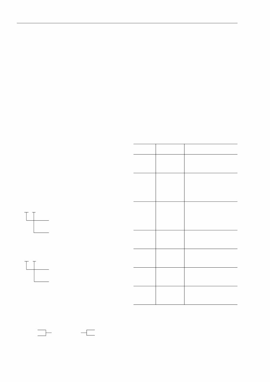
SYMBOLS
So that the shop manual can be of ample practical
use, important safety and quality portions are
marked with the following symbols.
Symbol Item Remarks
k
Safety
Special safety precautions
are necessary when per-
forming the work.
a Caution
Special technical precau-
tions or other precautions
for preserving standards
are necessary when per-
forming the work.
4
Weight
Weight of parts of sys-
tems. Caution necessary
when selecting hoisting
wire, or when working pos-
ture is important, etc.
3
Tightening
torque
Places that require special
attention for the tightening
torque during assembly.
2 Coat
Places to be coated with
adhesives and lubricants,
etc.
5
Oil, water
Places where oil, water or
fuel must be added, and
the capacity.
6
Drain
Places where oil or water
must be drained, and
quantity to be drained.
}·
Each issued as one
volume to cover all
models
12-203
12-203-1
12-203-2
12-204
Added pages
FOREWORD HOISTING INSTRUCTIONS
00-7
HOISTING INSTRUCTIONS
HOISTING
k Heavy parts (25 kg or more) must be lifted
with a hoist, etc. In the DISASSEMBLY
AND ASSEMBLY section, every part
weighing 25 kg or more is indicated clearly
with the symbol
• If a part cannot be smoothly removed from the
machine by hoisting, the following checks
should be made:
1) Check for removal of all bolts fastening the
part to the relative parts.
2) Check for existence of another part causing
interference with the part to be removed.
WIRE ROPES
1) Use adequate ropes depending on the
weight of parts to be hoisted, referring to
the table below:
Wire ropes
(Standard "Z" or "S" twist ropes
without galvanizing)
★ The allowable load value is estimated to be one-
sixth or one-seventh of the breaking strength of
the rope used.
2) Sling wire ropes from the middle portion of the
hook.
Slinging near the edge of the hook may cause
the rope to slip off the hook during hoisting, and
a serious accident can result. Hooks have max-
imum strength at the middle portion.
3) Do not sling a heavy load with one rope alone,
but sling with two or more ropes symmetrically
wound onto the load.
k Slinging with one rope may cause turning
of the load during hoisting, untwisting of
the rope, or slipping of the rope from its
original winding position on the load, which
can result in a dangerous accident.
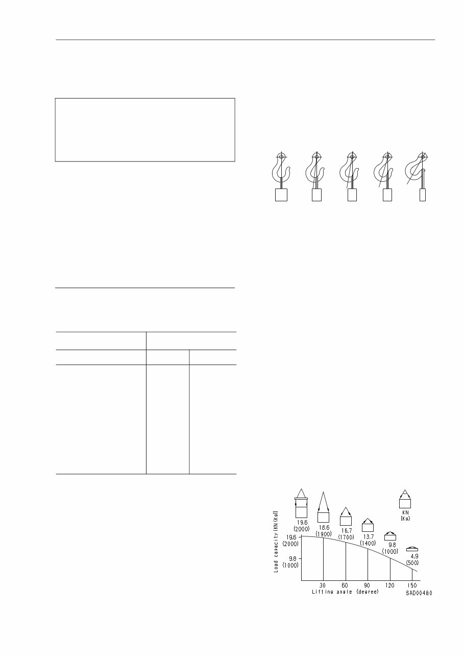
4) Do not sling a heavy load with ropes forming a
wide hanging angle from the hook.
When hoisting a load with two or more ropes,
the force subjected to each rope will increase
with the hanging angles. The table below
shows the variation of allowable load kN {kg}
when hoisting is made with two ropes, each of
which is allowed to sling up to 9.8 kN {1000 kg}
vertically, at various hanging angles.
When two ropes sling a load vertically, up to
19.6 kN {2000 kg} of total weight can be sus-
pended. This weight becomes 9.8 kN {1000 kg}
when two ropes make a 120° hanging angle.
On the other hand, two ropes are subjected to
an excessive force as large as 39.2 kN {4000
kg} if they sling a 19.6 kN {2000 kg} load at a
lifting angle of 150°.
Rope diameter Allowable load
mm kN tons
10
11.5
12.5
14
16
18
20
22.4
30
40
50
60
9.8
13.7
15.7
21.6
27.5
35.3
43.1
54.9
98.1
176.5
274.6
392.2
1.0
1.4
1.6
2.2
2.8
3.6
4.4
5.6
10.0
18.0
28.0
40.0
4
SAD00479
41% 71% 79% 88% 100%
FOREWORD METHOD OF DISASSEMBLING, CONNECTING PUSH-PULL TYPE COUPLER
00-8
METHOD OF DISASSEMBLING, CONNECTING PUSH-PULL TYPE COUPLER
k Before carrying out the following work, release
the residual pressure from the hydraulic tank.
For details, see TESTING AND ADJUSTING,
Releasing residual pressure from hydraulic
tank.
k Even if the residual pressure is released from
the hydraulic tank, some hydraulic oil flows out
when the hose is disconnected. Accordingly,
prepare an oil receiving container.
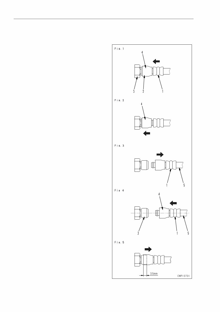
Disconnection
1) Release the residual pressure from the hydrau-
lic tank. For details, see TESTING AND
ADJUSTING, Releasing residual pressure from
hydraulic tank.
2) Hold adapter (1) and push hose joint (2) into
mating adapter (3). (See Fig. 1)
★ The adapter can be pushed in about 3.5
mm.
★ Do not hold rubber cap portion (4).
3) After hose joint (2) is pushed into adapter (3),
press rubber cap portion (4) against (3) until it
clicks. (See Fig. 2)
4) Hold hose adapter (1) or hose (5) and pull it out.
(See Fig. 3)
★ Since some hydraulic oil flows out, prepare
an oil receiving container.
Connection
1) Hold hose adapter (1) or hose (5) and insert it in
mating adapter (3), aligning them with each
other. (See Fig. 4)
★ Do not hold rubber cap portion (4).
2) After inserting the hose in the mating adapter
perfectly, pull it back to check its connecting
condition. (See Fig. 5)
★ When the hose is pulled back, the rubber
cap portion moves toward the hose about
3.5 mm. This does not indicate abnormality,
however.
Type 1
You're Reading a Preview
What's Included?
Fast Download Speeds
Online & Offline Access
Access PDF Contents & Bookmarks
Full Search Facility
Print one or all pages of your manual
$31.99
Viewed 85 Times Today


Secure transaction
What's Included?
Fast Download Speeds
Online & Offline Access
Access PDF Contents & Bookmarks
Full Search Facility
Print one or all pages of your manual
$31.99
Komatsu WA50-3 workshop manual is a comprehensive guide consisting of 394 pages. It is designed to assist both professional mechanics and DIY enthusiasts in efficiently repairing and overhauling the WA50-3 21450 and up models. The manual features easy-to-read text sections complemented by high-quality diagrams, pictures, and illustrations. It provides step-by-step instructions for fault finding and repair, ensuring accurate and timely completion of tasks while preventing errors. Additionally, the manual includes detailed specifications, tolerances, and explanations of component functions.


