Komatsu has had the operating and maintenance instructions translated into all the languages of the European Union. Should you require a copy in another language please inquire at your local dealer’s. 2SHUDWLRQ0DLQWHQDQH 0DQXDO Incorrect operation and maintenance of this machine may be hazardous and cause injuries. The operator and maintenance personnel must read this manual before commencing operation or maintenance. Keep this manual within reach at all times and ensure that operating personnel read it at regular intervals. SERIAL NUMBERS WA380H50051 AND UP :$+ VEAM920100 :+((//2$'(5 NOTE DANGER
.
FOREWORD 11
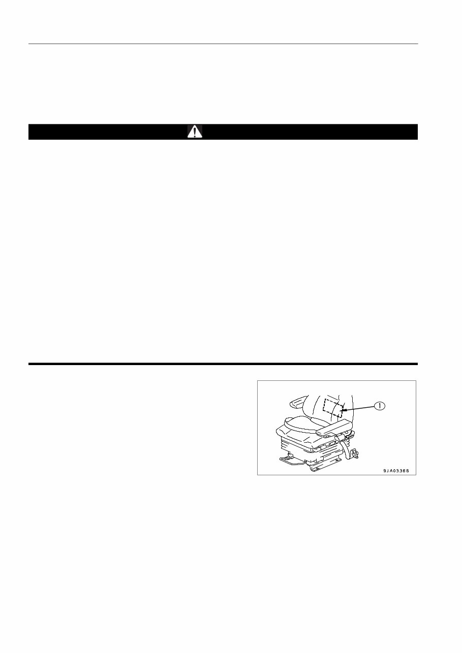
FOREWORD FOREWORD 1-2 FOREWORD 0. This manual provides rules and guidelines which will help you use this machine safely and effectively. The pre- cautions in this manual must be followed at all times when performing operation and maintenance. Most accidents are caused by the failure to follow fundamental safety rules for the operation and maintenance of machines. Acci- dents can be prevented by knowing beforehand conditions that may cause hazard when performing operation and maintenance. WARNING Operators and maintenance personnel must always do as follows before beginning operation or mainte- nance. Always be sure to read and understand this manual thoroughly before performing operation and maintenance. Read the safety messages given in this manual and the safety labels affixed to the machine thor- oughly and be sure that you understand them fully. Keep this manual at the storage location for the Operation and Maintenance Manual given below, and have all personnel read it periodically. If this manual has been lost or has become dirty and cannot be read, request a replacement manual immediately from Komatsu or your Komatsu distributor. If you sell the machine, be sure to give this manual to the new owners together with the machine. Komatsu delivers machines that comply with all applicable regulations and standards of the country to which it has been shipped. If this machine has been purchased in another country or purchased from someone in another country, it may lack certain safety devices and specifications that are necessary for use in your country. If there is any question about whether your product complies with the applicable standards and regulations of your country, consult Komatsu or your Komatsu distributor before operat- ing the machine. Storage location for the Operation and Maintenance Manual: Pocket (1) at rear of operator's seat
FOREWORD SAFETY INFORMATION 1-3 SAFETY INFORMATION 0. To enable you to use this machine safely, safety precautions and labels are given in this manual and affixed to the machine to give explanations of situations involving potential hazards and of the methods of avoiding such situa- tions. Signal words The following signal words are used to inform you that there is a potential hazardous situation that may lead to per- sonal injury or damage. In this manual and on machine labels, the following signal words are used to express the potential level of hazard. Indicates an imminently hazardous situation which, if not avoided, will result in death or seri- ous injury. This signal word is to be limited to most extreme situations. Indicates a potentially hazardous situation which, if not avoided, could result in death or serious injury. Indicates a potentially hazardous situation which, if not avoided, may result in minor or mod- erate injury. It may also be used to alert against unsafe practices. Example of safety message using signal word WARNING When standing up from the operator's seat, always place the safety lock lever in the LOCK position. If you accidentally touch the levers when they are not locked, this may cause a serious injury or damage. Other signal words In addition to the above, the following signal words are used to indicate precautions that should be followed to pro- tect the machine or to give information that is are useful to know. This word is used for precautions that must be taken to avoid actions which could shorten the life of the machine. This word is used for information that is useful to know. NOTICE REMARKS
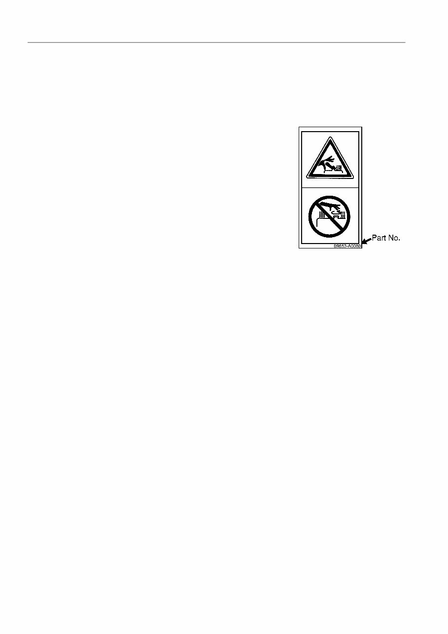
SAFETY INFORMATION FOREWORD 1-4 Safety labels Safety labels are affixed to the machine to inform the operator or maintenance worker on the spot when carrying out operation or maintenance of the machine that may involve hazard. This machine uses “Safety labels using words“ and “Safety labels using pictograms“ to indicate safety procedures. Safety labels using pictogram Safety pictograms use a picture to express a level of hazard- ous condition equivalent to the signal word. These safety picto- grams use pictures in order to let the operator or maintenance worker understand the level and type of hazardous condition at all times. Safety pictograms show the type of hazardous condi- tion at the top or left side, and the method of avoiding the haz- ardous condition at the bottom or right side. In addition, the type of hazardous condition is displayed inside a triangle and the method of avoiding the hazardous condition is shown inside a circle. Komatsu cannot predict every circumstance that might involve a potential hazard in operation and maintenance. Therefore, the safety messages in this manual and on the machine may not include all possible safety precau- tions. If any procedures or actions not specifically recommended or allowed in this manual are used, it is your responsi- bility to take the necessary steps to ensure safety. In no event should you engage in prohibited uses or actions described in this manual. The explanations, values, and illustrations in this manual were prepared based on the latest information available at that time. Continuing improvements in the design of this machine can lead to changes in detail which may not be reflected in this manual. Consult Komatsu or your Komatsu distributor for the latest available information of your machine or for questions regarding information in this manual. The numbers in circles in the illustrations correspond to the numbers in ( ) in the text. (For example: 1 -> (1))
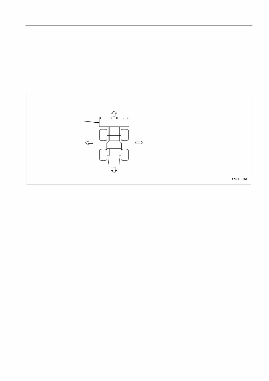
FOREWORD INTRODUCTION 1-5 INTRODUCTION 0. This Komatsu machine is designed to be used mainly for the following work: Digging work Smoothing Pushing work Loading work For details of the operating procedure, see “WORKING POSSIBILITY ( 3-97 )“. DIRECTIONS OF MACHINE 0. In this manual, the directions of the machine (front, rear, left, right) are determined according to the view from the operator's seat in the direction of travel (front) of the machine. Front Rear Right Left Bucket
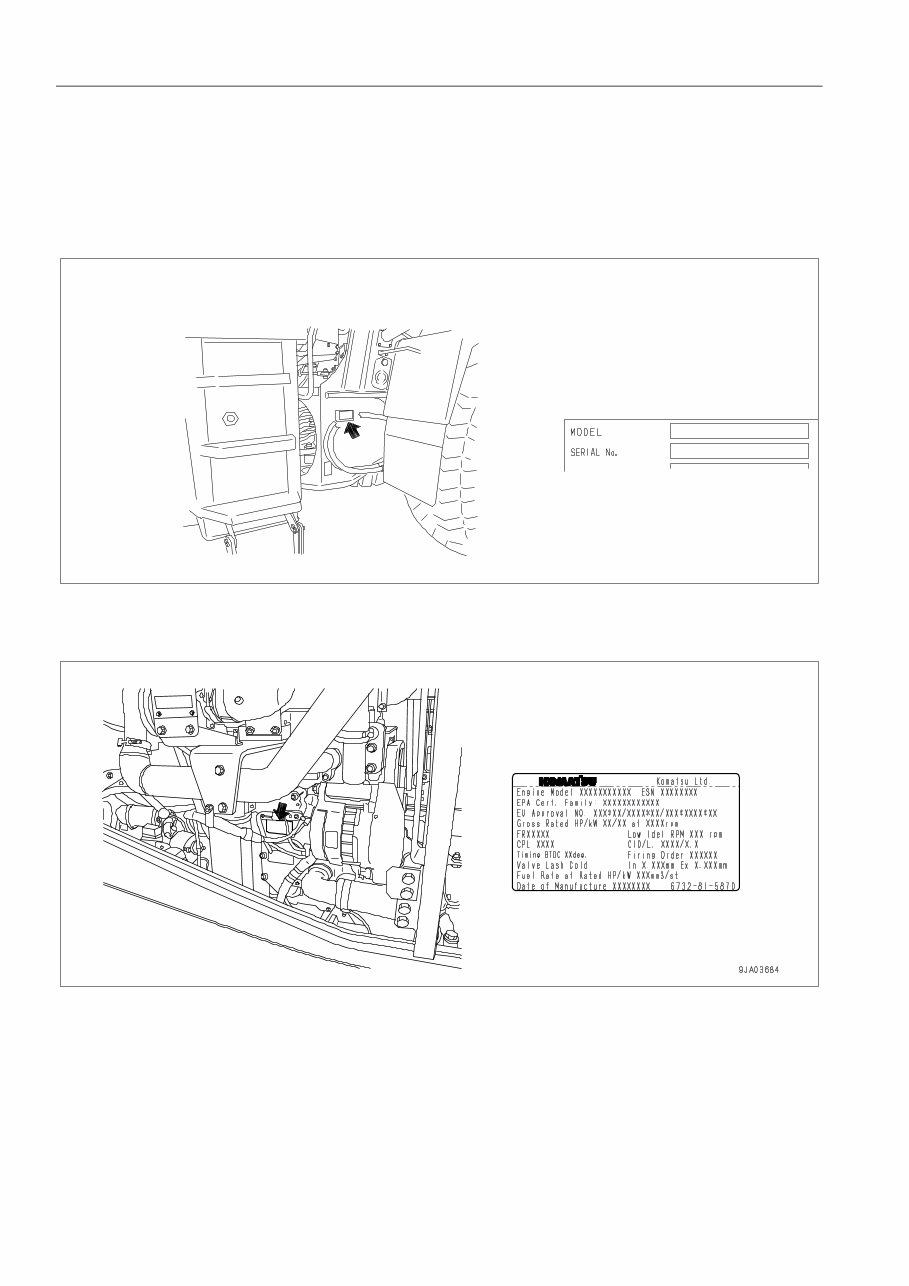
NECESSARY INFORMATION FOREWORD 1-6 NECESSARY INFORMATION 0. When requesting service or ordering replacement parts, please inform your Komatsu distributor of the following items. MACHINE SERIAL NO. PLATE AND POSITION 0. On the center right of the front frame. ENGINE SERIAL NO. PLATE AND POSITION 0. This name plate is affixed on the oil cooler at the side of engine cylinder block on the left side of machine. EPA: Environmental Protection Agency, U.S.A.
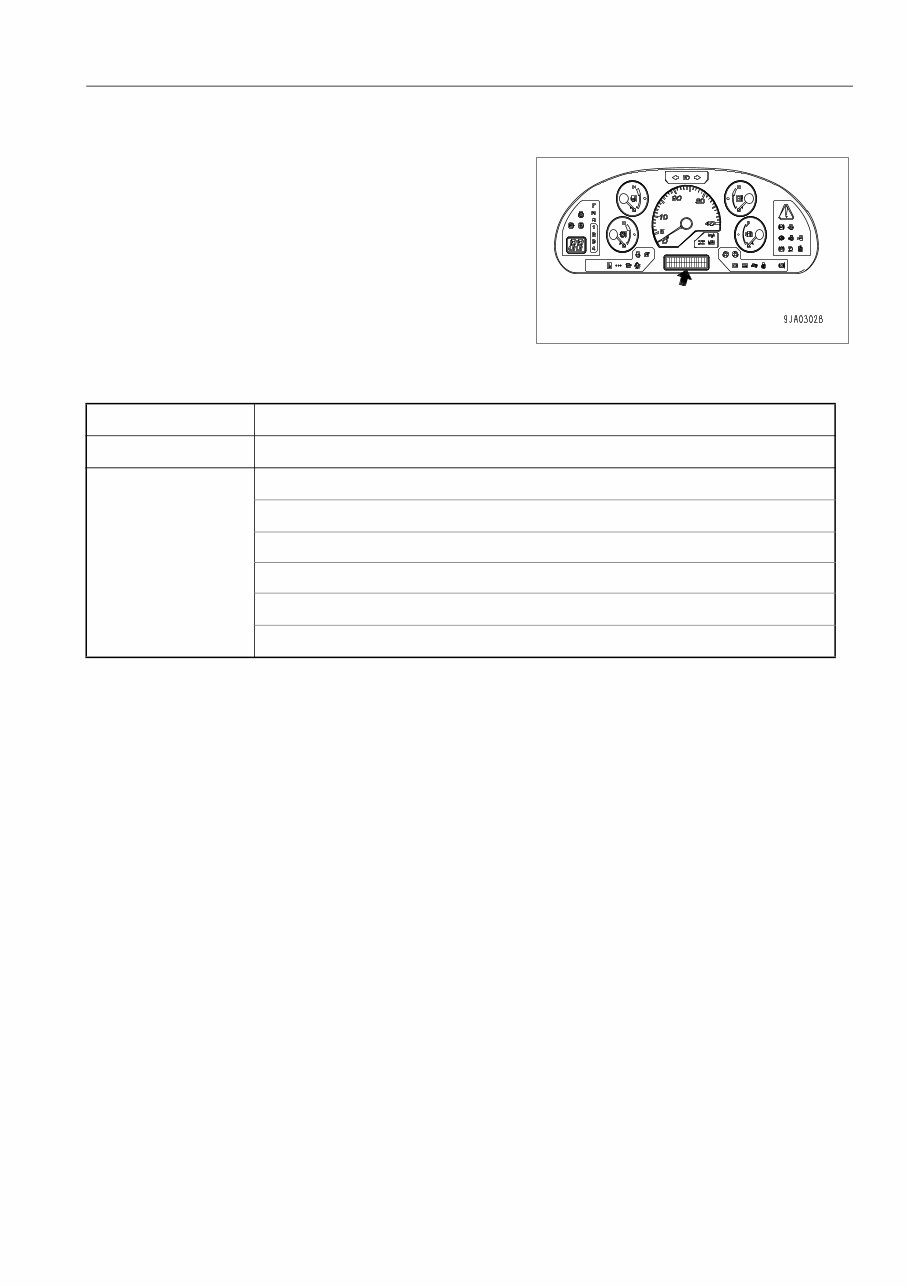
FOREWORD NECESSARY INFORMATION 1-7 POSITION OF SERVICE METER 0. It is at the center bottom of the machine monitor. For details of the service meter display, see SERVICE METER in EXPLANATION OF COMPONENTS “SERVICE METER ( 3- 8 )“. TABLE TO ENTER SERIAL NO. AND DISTRIBUTOR 0. Machine serial No. Engine serial No. Distributor name Address Service Personal Phone/Fax
CONTENTS FOREWORD 1-8 CONTENTS 0. FOREWORD FOREWORD ......................................................................................................................................................... 1-2 SAFETY INFORMATION...................................................................................................................................... 1-3 INTRODUCTION................................................................................................................................................... 1-5 DIRECTIONS OF MACHINE ........................................................................................................................... 1-5 NECESSARY INFORMATION ............................................................................................................................. 1-6 MACHINE SERIAL NO. PLATE AND POSITION ............................................................................................ 1-6 ENGINE SERIAL NO. PLATE AND POSITION ............................................................................................... 1-6 POSITION OF SERVICE METER.................................................................................................................... 1-7 TABLE TO ENTER SERIAL NO. AND DISTRIBUTOR ................................................................................... 1-7 CONTENTS .......................................................................................................................................................... 1-8 SAFETY SAFETY ................................................................................................................................................................ 2-2 SAFETY LABELS................................................................................................................................................. 2-4 LOCATION OF SAFETY LABELS ................................................................................................................... 2-4 SAFETY LABELS............................................................................................................................................. 2-5 GENERAL PRECAUTIONS ................................................................................................................................. 2-6 PRECAUTIONS FOR OPERATION ................................................................................................................... 2-14 STARTING ENGINE ...................................................................................................................................... 2-14 OPERATION .................................................................................................................................................. 2-15 TRANSPORTATION ...................................................................................................................................... 2-21 BATTERY....................................................................................................................................................... 2-22 TOWING ........................................................................................................................................................ 2-24 PRECAUTIONS FOR MAINTENANCE .............................................................................................................. 2-25 PRECAUTIONS WITH TIRES ............................................................................................................................ 2-32 OPERATION GENERAL VIEW .................................................................................................................................................. 3-2 GENERAL VIEW OF MACHINE ...................................................................................................................... 3-2 GENERAL VIEW OF CONTROLS AND GAUGES .......................................................................................... 3-3 EXPLANATION OF COMPONENTS.................................................................................................................... 3-6 MACHINE MONITOR....................................................................................................................................... 3-6 TYPES OF WARNING ................................................................................................................................ 3-7 CENTRAL WARNING LAMP ...................................................................................................................... 3-7 CHARACTER DISPLAY PORTION ............................................................................................................ 3-8 EMERGENCY STOP ITEM ...................................................................................................................... 3-14 CAUTION ITEMS ...................................................................................................................................... 3-16 INSPECTION AND MAINTENANCE ITEM............................................................................................... 3-18 PILOT DISPLAY PORTION ...................................................................................................................... 3-22 METER DISPLAY PORTION .................................................................................................................... 3-26 OTHER FUNCTIONS OF MACHINE MONITOR ...................................................................................... 3-28 SWITCHES .................................................................................................................................................... 3-33 CONTROL LEVERS, PEDALS ...................................................................................................................... 3-45 STEERING TILT LOCK LEVER..................................................................................................................... 3-50 CAP WITH LOCK ........................................................................................................................................... 3-51 CAP WITH LOCK FOR THE FUEL TANK FILLER PORT ........................................................................ 3-51
This is a comprehensive Operation & Maintenance Manual for the KOMATSU WA380-5H WHEEL LOADER.
SERIAL NUMBERS: WA380H50051 AND UP
TABLE OF CONTENTS:
FOREWORD
SAFETY INFORMATION
INTRODUCTION
NECESSARY INFORMATION
CONTENTS
SAFETY
SAFETY LABELS
GENERAL PRECAUTIONS
PRECAUTIONS FOR OPERATIONS
PRECAUTIONS FOR MAINTENANCE
PRECAUTIONS WITH TIRES
OPERATION
GENERAL VIEW
EXPLANATION OF COMPONENTS
OPERATION
TRANSPORTATION
COLD WEATHER OPERATION
LONG-TERM STORAGE
TROUBLESHOOTING
MAINTENANCE
GUIDE TO MAINTENANCE
OUTLINE OF SERVICE
WEAR PARTS
FUEL, COOLANT AND LUBRICANTS
STANDARD TIGHTENING TORQUES
PERIODIC REPLACEMENT OF SAFETY CRITICAL PARTS
MAINTENANCE SCHEDULE CHART
SERVICE PROCEDURE
SPECIFICATIONS
ATTACHMENTS, OPTIONS
SELECTING BUCKET AND TIRES
HANDLING LOAD METER
HANDLING TORQUE CONVERTER LOCK-UP
HANDLING AUTOMATIC AIR-CONDITIONER
CENTRAL LUBRICATION
JOYSTICK STEERING SYSTEM
EPC WORK EQUIPMENT LEVER
INDEX
Model Specification: KOMATSU WA380-5H WHEEL LOADER
Language: English
File Format: .PDF
Total Pages: 299
Requirements: Adobe Reader
ZOOM IN/OUT: YES
Printable: YES
Compatible: All Versions of Windows & Mac
This manual describes procedures for operation, handling, lubrication, maintenance, checking, and adjustment. It will help the operator and maintenance personnel realize peak performance through effective, economical, and safe machine operation and maintenance.
Instant delivery upon receipt of your payment.
This Manual is BOOKMARKED & SEARCHABLE so you can easily find what you are looking for.
Tons of pictures and diagrams at your fingertips!!
All pages are printable, so run off what you need & take it with you into the garage or workshop.
Save Money $$ By doing your own repairs! These manuals make it easy for any skill level with these very easy to follow, step-by-step instructions!