CEAM001500 WHEEL LOADER SERIAL NUMBERS WA250-3L A70001 and up MAY 97
PRODUCT PUBLICATIONS INFORMATION VARIOUS PRODUCT PARTS & SERVICE PUBLICATIONS ARE AVAILABLE TO ALL KOMATSU CONSTRUCTION EQUIPMENT OWNERS, INCLUDING OPERATION & MAINTENANCE MANUALS, PARTS BOOKS AND SHOP MANUALS. SPECIAL PUBLICATIONS SUCH AS SERVICE TOOL, AIR CONDITIONING, AND TURBOCHARGER SHOP MANUALS ARE ALSO AVAILABLE AS WELL AS SELECTED OPERATION & MAINTENANCE AND SHOP MANUALS IN FOREIGN LANGUAGES. THE PUBLICATIONS LISTED BELOW ARE AVAILABLE FOR THIS PARTICULAR MACHINE(S). DESCRIPTION FORM NUMBER PARTS BOOK - PAPER: Engine and Chassis ..................................................... BEPB002300 PARTS BOOK - MICROFICHE: Engine and Chassis ..................................................... BEPM002300 OPERATION & MAINTENANCE MANUAL: Chassis .............................................................. CEAM001500 SHOP MANUAL: Chassis .............................................................. CEBM001300 Engine ............................................................... SEBM010002 SAFETY MANUAL .......................................................... WLT70-1 PARTS AND SERVICE PUBLICATIONS CAN ONLY BE ACQUIRED BY AUTHORIZED KOMATSU DISTRIBUTORS, USING THE KOMATSU AMERICA INTERNATIONAL COMPANY PARTS INVENTORY PROCESSING SYSTEM (PIPS). IF THE PIPS SYSTEM IS NOT AVAILABLE AT THE DISTRIBUTOR LOCATION, THEN THE FOLLOWING REQUISITION FOR TECHNICAL SERVICE PUBLICATIONS AND SERVICE FORMS CAN BE USED. FORM KDC91D IS SHOWN ON THE REVERSE SIDE OF THIS PAGE. PUBINFO.KOM 121296
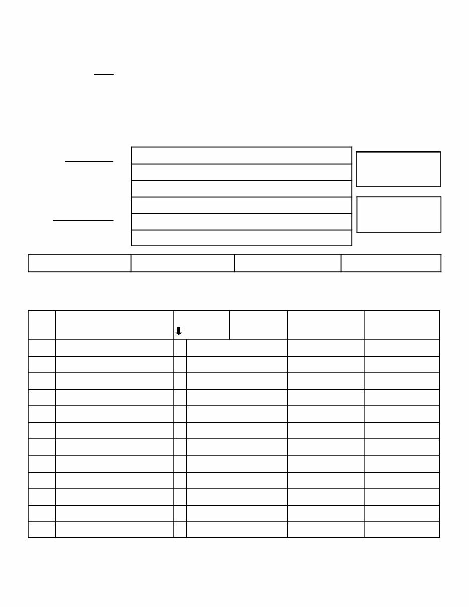
PURCHASE ORDER NO. ORDER DATE REQUISITION FOR TECHNICAL SERVICE PUBLICATIONS AND SERVICE FORMS COMPLETE FORM AND RETURN TO < Komatsu America International Company 440 North Fairway Drive Vernon Hills, IL 60061-8112 U.S.A. Attn: Technical Publications Fax No. (847) 970-4186 Tel No. (847) 970-5887 COMPANY NAME ATTN. STREET ADDRESS CITY, STATE, ZIP CODE COUNTRY SHIP TO < TYPE or PRINT ONLY < PHONE NO. FAX NO. SHIPPING METHOD DISTR/BRANCH CODE IMPORTANT - TO ASSURE SHIPMENT OF THE CORRECT PUBLICATION(S), THE MODEL NUMBER AND MACHINE SERIAL NUMBER MUST BE SHOWN. QTY. PUBLICATION FORM NO. P-Paper MODEL NUMBER SERIAL NUMBER PARTS BOOK M-Microfiche PUBLICATION DESCRIPTION KDC91D 121296 CURRENT PRICES WILL BE CHARGED
0-1 INTRODUCTION
INTRODUCTION 0-2 1. FORWARD This manual describes procedures for operation, handling, lubrication, maintenance, checking, and adjustment. It will help the operator and maintenance personnel realize peak performance through effective, economical and safe machine operation and maintenance. Keep this manual handy and have all personnel read it periodically. If this manual is lost or becomes dirty and can not be read, request a replacement manual from your local distributor. If you sell the machine, be sure to give this manual to the new owner. Continuing improvements in the design of this machine can lead to changes in detail, which may not be reflected in this manual. Consult your local distributor or Komatsu America International Company for the latest available information on your machine or for questions regarding information in this manual. WARNING ! Improper operation and maintenance of this machine can be hazardous and could result in serious injury or death. ! Operators and maintenance personnel must read this manual thoroughly before operating or maintaining this machine. ! This manual should be kept near the machine for reference and periodically reviewed by all personnel who come across it. ! Some actions involved in operation and maintenance can cause a serious accident, if they are not performed in the manner described in this manual. ! The procedures and precautions given in this manual apply only to intended uses of the machine. If you use your machine for any unintended uses that are not specifically prohibited, you must be sure that it is safe for you and others. In no event should you or others engage in prohibited uses or actions as described in this manual. ! Komatsu America International Company delivers machines that comply with all applicable regulations and standards of the country to which it has been shipped. If this machine has been purchased in another country or purchased from someone in another country, it may lack certain safety features and specifications that are necessary for use in your country. If there is any question about whether your product complies with the applicable standards and regulations of your country, consult your local distributor or Komatsu America International Company before operating the machine. ! The description of safety is given in SAFETY INFORMATION on page 0-3 and in SAFETY on page 1-1.
INTRODUCTION 0-3 2. SAFETY INFORMATION Most accidents are caused by the failure to follow fundamental safety rules for the operation and maintenance of machines. To avoid accidents, read, understand and follow all precautions and warnings in this manual and on the machine before performing maintenance and machine operations. To identify safety messages in this manual and on machine product graphics, the following signal words are used. DANGER! - This word is used on safety messages and product graphics where there is a high probability of serious injury or death if the hazard is not avoided. These safety messages and product graphics usually describe precautions that must be taken to avoid the hazard. Failure to avoid this hazard may also result in serious damage to the machine. WARNING! - This word is used on safety messages and product graphics where there is a potentially dangerous situation, which could result in serious injury or death if the hazard is not avoided. These safety messages and product graphics usually describe precautions that must be taken to avoid the hazard. Failure to avoid this hazard may also result in serious damage to the machine. CAUTION! - This word is used on safety messages and product graphics for hazards, which could result in minor or moderate injury if the hazard is not avoided. These safety messages and product graphics might also use this word for hazards where the only result could be damage to the machine. NOTICE - This word is used for precautions that must be taken to avoid actions, which could shorten the life of the machine. Safety precautions are described in SAFETY beginning on page 1-1. Komatsu America International Company cannot predict every circumstance that might involve a potential hazard in operation and maintenance. Therefore the safety message in this manual and on the machine may not include all possible safety precautions. If any procedures or actions not specifically recommended or allowed in this manual are used, you must be sure that you and others can do such procedures and actions safely and without damaging the machine. If you are unsure about the safety of some procedures, contact your local distributor or Komatsu America International Company.
INTRODUCTION 0-4 3. INTRODUCTION 3.1 INTENDED USE This WHEEL LOADER is designed to be used mainly for the following work: ! Digging ! Leveling ! Pushing ! Loading For details of the operating procedures, see "12.13 WORK POSSIBLE USING WHEEL LOADER" on page 2-52 3.2 FEATURES ! Curved glass and improved sealing for reduced noise, low vibration cab. ! Console and steering post with unencumbered foot area providing the same comfortable feeling as in an automobile ! Maintenance-free, wet-type disc parking brake (acts also as emergency brake). ! One-touch panel control and air conditioner with new refrigerant installed. ! Full fender system installed to help prevent mud or water from splashing on or around the machine. ! Light touch lever operations through use of electrical transmission control lever ! Pleasant operators compartment with low vibration and noise levels ! Large gull-wing side panels and a rear grill that opens fully for ease of maintenance ! Large safety lock lever for work equipment to ensure that operator does not forget to apply safety lock ! New engine that meets exhaust gas emission of 96 EPA & carb. 3.3 BREAKING IN A NEW MACHINE Your machine has been thoroughly adjusted and tested before shipment. However, operating the machine under severe conditions at the beginning can adversely affect the performance and shorten the machine life. Be sure to break in the machine for the initial 100 hours (as indicated by the service meter). During breaking in: ! After starting, let the engine idle for 5 minutes to allow proper engine warm-up prior to actual operation. ! Avoid operation with heavy loads or at high speeds. ! Avoid sudden starts or acceleration, unnecessarily abrupt stops and sharp steering except in cases of emergency. The precautions given in this manual for operating, maintenance, and safety procedures are only those that apply when this product is used for the specified purpose. If the machine is used for a purpose that is not listed in this manual, Komatsu America International Company cannot bear any responsibility for safety. All consideration of safety in such operations is the responsibility of the user. Operations that are prohibited in this manual must never be carried out under any circumstance.
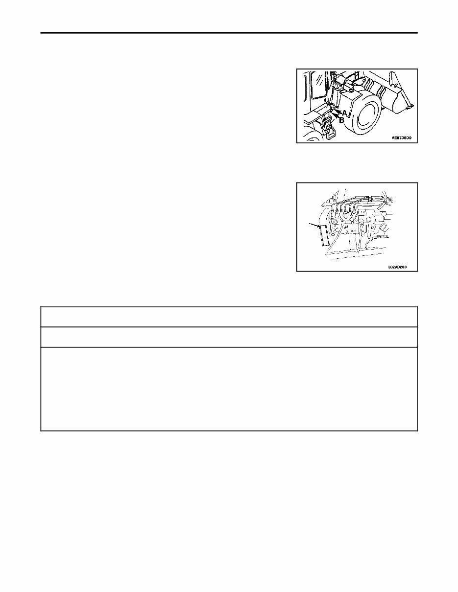
INTRODUCTION 0-5 4. LOCATION OF PLATES, TABLE TO ENTER SERIAL NO. AND DISTRIBUTOR 4.1 MACHINE SERIAL NO. PLATE POSITION (A) Position of plate On the center right of the front frame. (B) Position of stamp This is stamped on the center of the front frame on the right hand side of the machine. 4.2 ENGINE SERIAL NO. PLATE POSITION Position of plate As viewed from the right hand side of the machine. 4.3 TABLE TO ENTER SERIAL NO. AND DISTRIBUTOR Machine serial No.: Engine serial No.: Distributor name: Address: Phone: Service personnel for your machine: REMARKS
INTRODUCTION 0-6 5. CONTENTS INTRODUCTION 1. FORWARD .............................................................................. 0-2 2. SAFETY INFORMATION ................................................................... 0-3 3. INTRODUCTION ......................................................................... 0-4 3.1 INTENDED USE ........................................................................ 0-4 3.2 FEATURES ............................................................................ 0-4 3.3 BREAKING IN A NEW MACHINE .......................................................... 0-4 4. LOCATION OF PLATES, TABLE TO ENTER SERIAL NO. AND DISTRIBUTOR ...................... 0-5 4.1 MACHINE SERIAL NO. PLATE POSITION ................................................... 0-5 4.2 ENGINE SERIAL NO. PLATE POSITION .................................................... 0-5 4.3 TABLE TO ENTER SERIAL NO. AND DISTRIBUTOR .......................................... 0-5 5. CONTENTS ............................................................................. 0-6 SAFETY 6. GENERAL PRECAUTIONS ................................................................. 0-9 7. PRECAUTIONS DURING OPERATION ....................................................... 0-9 7.1 BEFORE STARTING ENGINE ............................................................ 0-12 7.2 AFTER STARTING ENGINE ............................................................. 0-21 7.3 TRANSPORTATION .................................................................... 0-22 7.4 BATTERY ............................................................................ 0-25 7.5 TOWING ............................................................................. 0-26 8. PRECAUTIONS FOR MAINTENANCE ....................................................... 0-26 8.1 BEFORE CARRYING OUT MAINTENANCE ................................................ 0-31 8.2 DURING MAINTENANCE ................................................................ 0-36 8.3 TIRES ............................................................................... 0-38 9. POSITION FOR ATTACHING SAFETY LABELS ............................................... 0-38 9.1 POSITION FOR ATTACHING SAFETY LABELS .............................................. 2-2 OPERATION 10. GENERAL VIEW ......................................................................... 2-2 10.1 GENERAL VIEW OF MACHINE .......................................................... 2-3 10.2 GENERAL VIEW OF CONTROLS AND GAUGES ........................................... 2-4 11. EXPLANATION OF COMPONENTS .......................................................... 2-4 11.1 METER, LAMPS ...................................................................... 2-6 11.1.1 WARNING DISPLAYS ............................................................. 2-13 11.1.2 METER DISPLAY PORTION ........................................................ 2-17 11.2 SWITCHES ......................................................................... 2-25 11.3 CONTROL LEVERS, PEDAL ........................................................... 2-30 11.4 STEERING COLUMN TILT LEVER ...................................................... 2-30 11.5 CAP WITH LOCK .................................................................... 2-30 11.5.1 METHOD OF OPENING AND CLOSING CAP WITH LOCK ............................... 2-32 11.6 SAFETY BAR ........................................................................ 2-32 11.7 TOWING PIN ........................................................................ 2-32 11.8 GREASE PUMP CLAMP AND RUBBER RING ............................................. 2-34
INTRODUCTION 0-7 11.9 BACKUP ALARM ..................................................................... 2-35 11.10 FUSE ............................................................................. 2-35 11.10.1 FUSE CAPACITY AND NAME OF CIRCUIT ............................................ 2-36 11.11 SLOW BLOW FUSE ................................................................ 2-37 11.12 STORAGE PLACE FOR THIS MANUAL ................................................ 2-37 11.13 AUXILIARY POWER SOURCE ........................................................ 2-37 11.13.1 FOR MACHINES EQUIPPED WITH ROPS CAB ........................................ 2-38 12. CHECK BEFORE STARTING ENGINE ...................................................... 2-38 12.1 WALK AROUND CHECK .............................................................. 2-42 12.2 CHECK BEFORE STARTING ........................................................... 2-42 12.2.1 CHECK COOLANT LEVEL, ADD COOLANT ........................................... 2-42 12.2.2 CHECK MONITOR PANEL ......................................................... 2-44 12.2.3 CHECK FUEL LEVEL, ADD FUEL ................................................... 2-44 12.2.4 CHECK OIL LEV EL IN ENGINE OIL PAN, ADD OIL ..................................... 2-46 12.2.5 CHECK AND REFILL OF OIL IN BRAKE OIL TANK ..................................... 2-46 12.2.6 CHECK DUST INDICATOR ......................................................... 2-47 12.2.7 CHECK ELECTRICAL WIRING ...................................................... 2-48 12.2.8 DRAIN THE WATER FROM THE FUEL-WATER SEPARATOR ........................... 2-48 12.2.9 CHECK EFFECT OF PARKING BRAKE ............................................... 2-50 12.2.10 CHECK EFFECT OF WHEEL BRAKES ............................................... 2-50 12.2.11 CHECK SOUND OF HORN AND BACKUP ALARM ..................................... 2-50 12.2.12 CHECK FLASHING OF LAMPS, CHECK FOR DIRT AND DAMAGE ........................ 2-50 12.2.13 CHECK ENGINE EXHAUST COLOR AND SOUND ..................................... 2-50 12.2.14 CHECK OPERATIONS OF GAUGES ................................................. 2-50 12.2.15 CHECK PLAY OF STEERING WHEEL, CHECK OPERATION OF STEERING ................ 2-50 12.2.16 CHECK DIRECTION OF REAR VIEW MIRROR, CHECK FOR DIRT OR DAMAGE ............ 2-50 12.2.17 CHECK LOCK OF CAB DOOR FOR MACHINES EQUIPPED WITH CAB .................... 2-51 12.3 ADJUSTMENT BEFORE OPERATION ................................................... 2-51 12.3.1 OPERATOR'S SEAT .............................................................. 2-53 12.3.2 ADJUST SEAT BELT .............................................................. 2-55 12.3.3 ADJUST REAR VEIW MIRRORS .................................................... 2-56 12.4 OPERATIONS AND CHECKS BEFORE STARTING ENGINE ................................. 2-58 12.5 STARTING ENGINE .................................................................. 2-58 12.5.1 NORMAL STARTING PROCEDURES IN COLD AND WARM CONDITIONS ................. 2-60 12.5.2 STARTING PROCEDURES AFTER EXTENDED SHUTDOWN OR OIL CHANGE ............ 2-60 12.5.3 STARTING PROCEDURES AFTER CHANGING FUEL FILTERS .......................... 2-60 12.5.4 STARTING PROCEDURES AFTER RUNNING OUT OF FUEL ............................ 2-62 12.6 OPERATIONS AND CHECKS AFTER STARTING ENGINE .................................. 2-63 12.7 MOVING MACHINE OFF ............................................................... 2-66 12.8 CHANGING GEAR SPEED ............................................................. 2-66 12.9 CHANGING DIRECTION .............................................................. 2-67 12.10 TURNING ......................................................................... 2-68 12.11 STOPPING MACHINE ............................................................... 2-69 12.12 OPERATION OF WORK EQUIPMENT .................................................. 2-70 12.13 WORK POSSIBLE USING WHEEL LOADER ............................................ 2-70 12.13.1 DIGGING OPERATIONS WITH ROCK PILES .......................................... 2-71 12.13.2 DIGGING OPERATIONS ON LEVEL GROUND ......................................... 2-72 12.13.3 LEVELING OPERATION ........................................................... 2-72 12.13.4 PUSHING OPERATIONS ........................................................... 2-72 12.13.5 LOAD AND CARRY OPERATIONS ................................................... 2-73 12.13.6 LOADING OPERATIONS ........................................................... 2-74 12.14 PRECAUTIONS FOR OPERATION .................................................... 2-74 12.14.1 PERMISSIBLE WATER DEPTH ..................................................... 2-74 12.14.2 IF WHEEL BRAKE DOES NOT WORK ................................................ 2-74 12.14.3 PRECAUTIONS WHEN DRIVING UP OR DOWN SLOPES ............................... 2-75 12.14.4 PRECAUTIONS WHEN DRIVING MACHINE ........................................... 2-76 12.15 ADJUSTING WORK EQUIPMENT POSTURE ........................................... 2-76 12.15.1 ADJUSTING BOOM KICKOUT ...................................................... 2-77
This manual describes procedures for operation, handling, lubrication, maintenance, checking, and adjustment. It will help the operator and maintenance personnel realize peak performance through effective, economical and safe machine operation and maintenance.
All manuals are Windows Vista32 and 64, XP, ME, 98, NT, 2000 compatible and work with Mac!
Upon receipt of your payment, you can instantly find, print, use, and then dispose of it. Tons of pictures and diagrams are at your fingertips. All pages are printable, so you can run off what you need and take it with you into the garage or workshop. Save money by doing your own repairs with these very easy to follow, step-by-step instructions! Instant means no shipping cost or waiting for a CD to arrive in the mail. You will receive this manual today via instant download on completion of payment via our secure payment processor. We accept all major credit/debit cards/PayPal.










 Lifetime Access




