6-45 1. HYDRAULIC OIL CLEAN UP PROCEDURE USING PORTABLE FILTER CADDY 1. HYDRAULIC OIL CLEAN UP PROCEDURE USING PORTABLE FILTER CADDY Service equipment and tool ·Portable filter caddy ·Two 4000 mm × 1in 100R1 Hoses ·Quick disconnect fittings. ·Discharge wand ·Various size fittings. Brake system uses oil from hydraulic oil tank. Flush all lines in the brake, pilot, steering system and cut off system. Disassemble and clean major components for brake and steering system. Remove and clean pilot caps from main control valve. Brake and steering components may fail if brake and steering system is not cleaned after hydraulic oil tank contamination. If hydraulic system is contaminated due to a major component failure, remove and disassemble steering cylinders to clean debris from cylinders. Install a new return filter element. Inspect filter housing before installing new element. For a failure that creates a lot of debris, remove access cover from hydraulic oil tank. Drain and clean hydraulic oil tank of fill the specified oil to hydraulic oil tank through upper cover. To minimize oil loss, pull a vacuum in hydraulic oil tank using a vacuum pump. Connect filter caddy suction line to drain port at bottom of hydraulic oil tank using connector. Check to be sure debris has not closed drain port. Put filter caddy discharge line into hydraulic oil tank filler hole so end is as far away from drain port as possible to obtain a thorough cleaning of oil. ※ ※ 1) 2) ※ 3) 4) GROUP 3 TESTS AND ADJUSTMENTS GROUP 3 TESTS AND ADJUSTMENTS
6-46 Start the filter caddy. Check to be sure oil is flowing through the filters. Operate filter caddy approximately 10 minutes so oil in hydraulic oil tank is circulated through filter a minimum of four times. Hydraulic oil tank capacity : 102 ℓ(26.9 U.S. gal) Leave filter caddy operation for the next steps. Start the engine and run it at high idle. For the most effective results, cleaning procedure must start with the smallest capacity circuit then proceed to the next largest capacity circuit. Operate all functions, one at a time, through a complete cycle in the following order: Clam, steering, bucket, and boom. Also include all auxiliary hydraulic functions. Repeat procedure until the total system capacity has circulated through filter caddy seven times, approximately 30 minutes. Each function must go through a minimum of three complete cycles for a through cleaning for oil. Filtering time for machines with auxiliary hydraulic functions must be increased because system capacity is larger. Stop the engine. Remove the filter caddy. Install a new return filter element. Check oil level in reservoir; Add oil if necessary. 5) ※ 6) ※ 7) ※ 8) 9) 10)
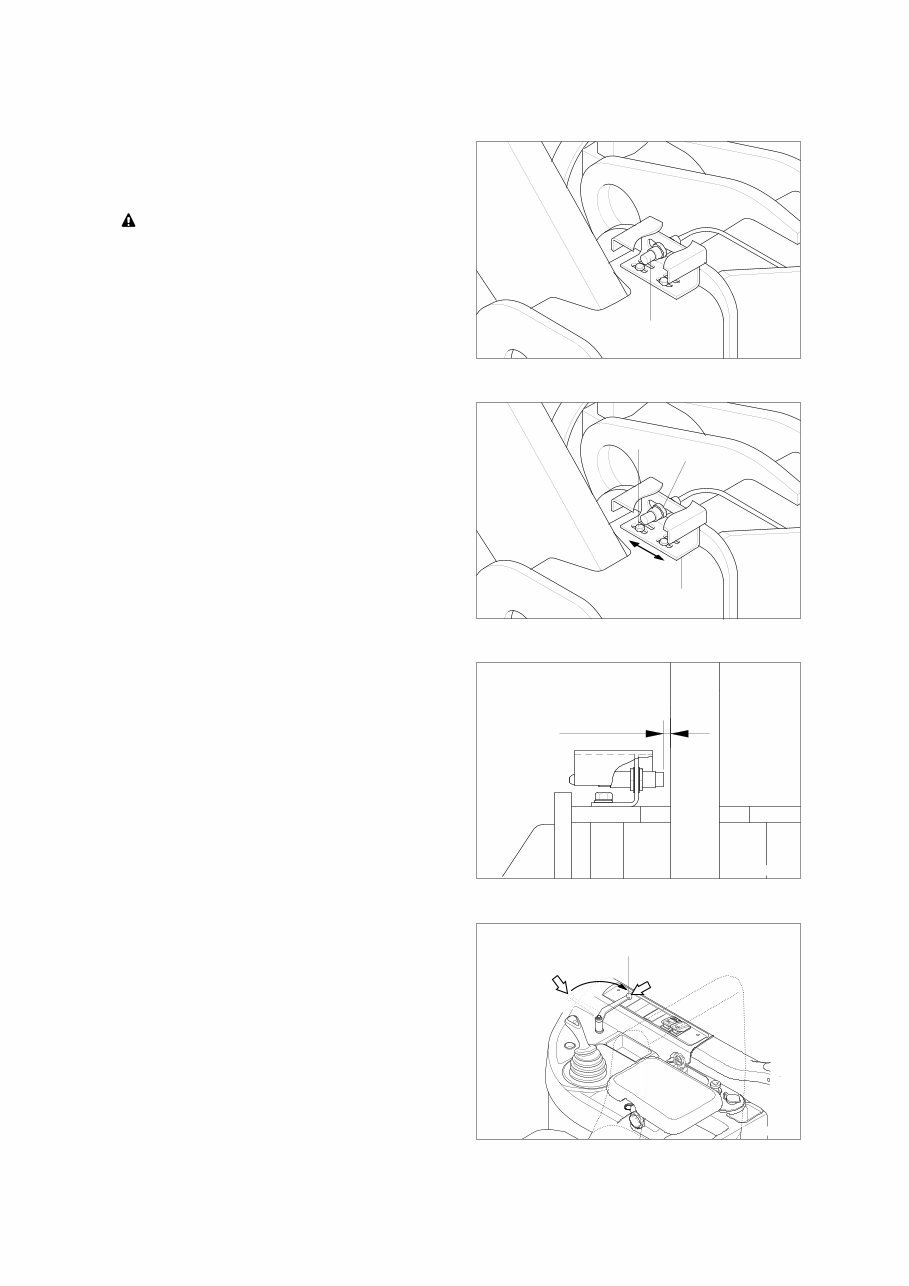
6-47 2. BOOM HEIGHT KICKOUT ADJUSTMENT 2. BOOM HEIGHT KICKOUT ADJUSTMENT Lift the boom up to a desired height, set the boom control lever at hold, then stop the engine. Be careful lest work equipment fall down. Be careful lest work equipment fall down. Put the hydraulic safety lock lever in the Put the hydraulic safety lock lever in the LOCK position. LOCK position. Boom Proximate switch 7707WE20 1) Loosen nuts and bolts then tighten them after adjusting the plate or proximate switch so that it comes in contact with the center of the probe of the proximate switch. Boom Plate Bolt Nut 7707WE21 2) Loosen the nuts so that a clearance between the plate and the probe of the proximate switch are maximum 6 mm. Max 6mm Boom 7707WE22 3) Start the engine. Position the bucket on the ground. Then lift the bucket to a desired height by using the control lever and release the hand. Confirm the lever automatically returns to the neutral position and the boom (the bucket) stop at the adjusted position. P Lock Unlock Hydraulic safety lever 7409S4OP25 4)
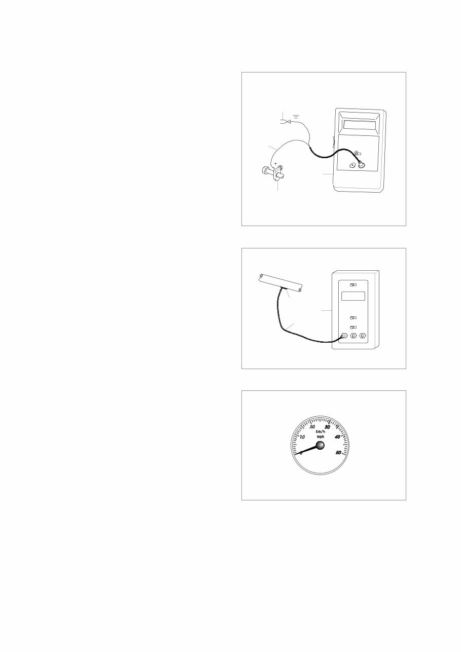
6-48 3. TEST TOOLS 3. TEST TOOLS CLAMP-ON ELECTRONIC TACHOMETER CLAMP-ON ELECTRONIC TACHOMETER INSTALLATION INSTALLATION ·Service equipment and tools Tachometer A : Clamp on tachometer. Remove paint using emery cloth and connect to a straight section of injection line within 100 mm (4 in) of pump. Finger Tighten only-do not over tighten. B : Black clip ( - ). Connect to main frame. C : Red clip (+). Connect to transducer. D : Tachometer readout. Install cable. A C B D C B A DIGITAL THERMOMETER INSTALLATION DIGITAL THERMOMETER INSTALLATION ·Service equipment and tools Digital thermometer A : Temperature probe. Fasten to a bare metal line using a tie band. Wrap with shop towel. B : Cable. C : Digital thermometer. DISPLAY MONITOR TACHOMETER DISPLAY MONITOR TACHOMETER The display monitor tachometer is accurate enough for test work. 1) 2) 2) 3) 3) 75795SE32 75795SE33 75795SE35
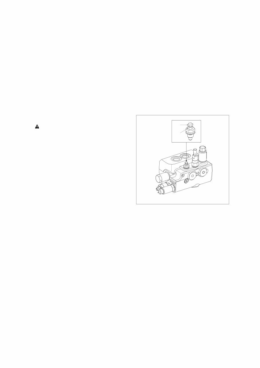
6-49 4. HYDRAULIC OIL WARM UP PROCEDURE 4. HYDRAULIC OIL WARM UP PROCEDURE Install temperature reader (see temperature reader installation procedure in this group). Run engine at high idle. Hold a hydraulic function over relief to heat the oil. Periodically cycle all hydraulic functions to distribute warm oil. Heat oil to test specification (approx. 45˚C). 1) 2) 3) 4) 5) A B Ride control valve Ride control system (option) Ride control system (option) Attention Attention Before carrying out any maintenance work the accumulators must be unloaded (zero pressure). For this, loosen the nut (A) and bolt (B) counterclockwise with 10 mm spanner. The accumulator will be unloaded (zero pressure) in less than a minute. The lifting system must firstly be secured against lowering. After carrying out maintenance work, screw the bolt (B) and nut (A). ·Tightening torque A : 2.04 kgf·m (14.8 lbf·ft) ※ 1) 2) ※ 3) 4) 7607S6WE28
The Hyundai Wheel Loader HL740-9 Service Manual is designed to improve the quality of repairs by providing accurate understanding of the product and correct repair procedures. It contains necessary technical information for operation performed in a service workshop. This manual covers safety hints, specifications, operation checkout record sheet, engine, power train system, brake system, steering system, work equipment, electrical system, and more.
The Hyundai Wheel Loader HL740-9 Operating Manual contains instructions and safety recommendations for driving, handling, lubrication, maintenance, inspection, and adjustment of the equipment. It promotes safety maintenance and enhances machine performance. This manual covers safety hints, specifications, control device, operation, transportation, maintenance, troubleshooting guide, and more.