




1. GENERAL INFOMATION
1-1. Common Items ・・・・・・・・ 1-1-1
1-2. Specifications ・・・・・・・・・ 1-2-1
1


1-1. COMMON ITEMS
Scope of Description and Usage of This Manual ・・・・・ 1-1-1
Precautions in Inspection and Service ・・・・・・・・・ 1-1-4
General Precautions for Inspection and Service ・・・・・ 1-1-6
General Precautions for Safety Operation ・・・・・・・・・ 1-1-7
Disassembly and Assembly ・・・・・・・・ 1-1-15
1 – 1


1-1. Common Items 1. General Instructions
Scope of Description and Usage of This Manual
1-1-1
To Readers of This Manual
This manual provides service staff who have completed basic training with technical information necessary
for service activity. For obtaining satisfaction and trust from customers, you are expected to read through
this manual and acquire correct product knowledge and service technique.
Reference Material
This manual does not, in principle, describe basic items and overlapped areas with other materials (below)
to eliminate redundancy.
• For basic items, refer to training materials such as "Sales and Technical Material."
• For handling and inspection procedures, refer to "Instruction Manual."
• For structure and component parts, refer to "Parts Catalog."
• For handling, maintenance procedure and parts of the engine, refer to materials issued by the engine
manufacturer.
Organization
This manual is organized into four parts: 1. General Instructions 2. Construction and Function 3. Oveahaul
4. Troubleshooting
1. General Instructions
Safety during maintenance work and general cautionary instructions are compiled.
2. Construction and Function
An explanation of the construction and function and an explanation of operation (function) by
illustrations, circuit diagrams and system diagrams are compiled.
3. Oveahaul
Methods of removing hydraulic equipment from a vehicle, its disassembly and reassembly, its adjusting
method, standard values used for service work and service limits are compiled.
4. Troubleshooting
Probable causes and corrections for troubles are compiled.
1-1. Common Items 1. General Instructions
Scope of Description and Usage of This Manual
1-1-2
Items Listed in This Manual
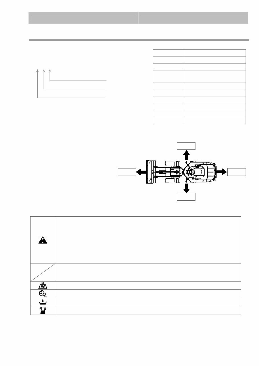
z Page number (3 digit indication)
Note) If a page number has a 2 digit indication, the
second digit shows the page in each chapter.
Equipment code: Refer to the right table.
z Position and direction of vehicle
Respective positions and directions of a
vehicle are indicated in the traveling
direction of the vehicle (illustration on
the right).
z Symbols and notation
: Items that require special cautions are indicated in a box to prevent personal injuries or
damages to the equipment.
DANGER : indicates immediate hazards that WILL result in death or severe injury in a
box.
WARNING: indicates potential hazards or unsafe practices that COULD result in death
or severe injury in a box.
CAUTION: indicates potential hazards or unsafe practices that MAY result in minor or
medium injury in a box.
IMPORTANT: indicates important items for operation and maintenance in a box.
NOTE: indicates informative items such as technical information and know-how in
a box.
: indicates a mass of parts that require caution when held or moved.
: indicates a specifically set value (torque) when bolts are tightened.
: indicates a volume of discharged water or oil.
: indicates a volume of filled water or oil.
Equipment Equipment name
0 Engine
1 Electric system
2
Power train I
(HST, reduction gear)
3 Power train II (Axle)
4 Brake
5 Steering
6 Frame
7 Hydraulic system
8 Working equipment
Right
Left
Rear Front
2 - 0 - 1
Page in each chapter
Number of chapter
Equipment code

1-1. Common Items 1. General Instructions
Scope of Description and Usage of This Manual
1-1-3
z Indication of Unit
In this manual, unit indication of quantity and
unit is mainly based on SI (International
System) unit system (right table).
Example of main unit conversion
SI unit (Conventional unit)
Pressure 1 MPa (10.197 kgf/cm
2
)
Force 1 N (0.10197 kgf)
Torque 1 Nm (0.10197 kgf·m)
Power 1 kW (1.360 PS)

1-1. Common Items 1. General Instructions
Precautions in Inspection and Service
1-1-4
This section provides the information which is helpful for disassembling and assembling the machine
properly and covers the safety precautions and general instructions.
Dust Prevention
The most important precaution for maintaininig the
longer service life of a machine is to prevent dirt
and dust from adhering to the important moving
parts. On our produsts, special attention is paid to
prevent dirt and dust from getting into each moving
part. In a word, an important parts is enclosed and,
further, provided with a seal or filter and, thereby,
clean air, fule and lubricant are always sent to
each part.
When disconnecting hydraulic, fuel, lubricating or
air pipes and hoses for disassembly, clean each
connection and around the connection thoroughly.
After disconnectiong the pipes and hoses,
immediately cover each opening with a cap, plug
or tape to prevent entry of foreign material. When
removing an inspection cover or plate also do the
same way.
Wash and check all parts removed. Check to see
that all oil passages and oil holes are not clogged.
Cover all parts to prevent dirt and dust from
adhering to each part and, when reinstalling each
part, check to see that it is clean. On a new part,
do not unpack the part until it is installed.
Engine Overhaul Timing
For details, refer to the documents supplied by the
engine manufacturer.
Precaution for Hydraulic and Pneumatic
Systems
When impurities such as dirt and dust enter the
hydraulic and pneumatic systems, the operation is
affected adversely and, further, the parts in the
system are damaged excessively to result in the
failures of the machine.
Accordingly, when the parts in the hydraulic and
pneumatic systems have been removed, cover the
openings. Further, when pieces of broken metal
and rubber have been found in the hydraulic
system, flush the whole of the system. Remove
and install the parts related to the hydraulic and
pneumatic systems in a clean place. Wash all
metallic parts in uninflammable safety solvent and
coat them with lubricating oil for easier instllation.
Danger Prevention
Before servicing the hydraulic system for the
working equipments, perform the following steps:
(1) Lower all working equipments (bucket, etc.) on
the ground. If a working equipment must be
removed while holding it in a certain position,
refer to “Disassembly and Assembly”.
(2) Stop the engine and move each working
equipment control lever to all positions to make
sure that no pressure is applied to the
hydraulic system.
(3) Set all control levers to neutral and lock them.
Hydraulic and Pneumatic Valves
Check all valves, valve holes and valve seats for
scratches and folds. Remove them with a fine oil
stone or sand paper. All the valves should move
smoothly in their respective holes. Make sure that
all passages are free from foregin materials and
clean.
1-1. Common Items 1. General Instructions
Precautions in Inspection and Service
1-1-5
Hydraulic and Pneumatic Pipes and
Hoses
When connectiong a metallic pipe, first
finger-tighten all bolts and then tighten each end
and attaching bracket bolts. After connecting the
pipe, connect the hose. At this time, finger-tighten
the bolts at both of the hose as a temporary
measure. Take care not to allow the hose to come
in contact with the parts and other hoses, reduce
the bend and twist and then tighten the coupling
bolts.
A hydraulic hoses has its own bending pattern
depending on the manufacturing method.
Accordingly, when bending a hydraulic hose for
connecting, bend according to the bending pattern.
Furhter, when replacing a hose provided with
angled stem, assemble and connect with the hose
bending pattern fully taken into consideration.
After connecting the hoses, proceed as follows:
Run the engine and move each control lever to
move the working equipments to position. (Refer to
“Bleeding Air from Hydraulic System” to be
mentioned later.)
During that time, observe each hose carefully.
Lower the working equipments on the ground, stop
the engine and then recondition the twist,
interference or excessively hanging, etc. of the
hose by turning the stem.
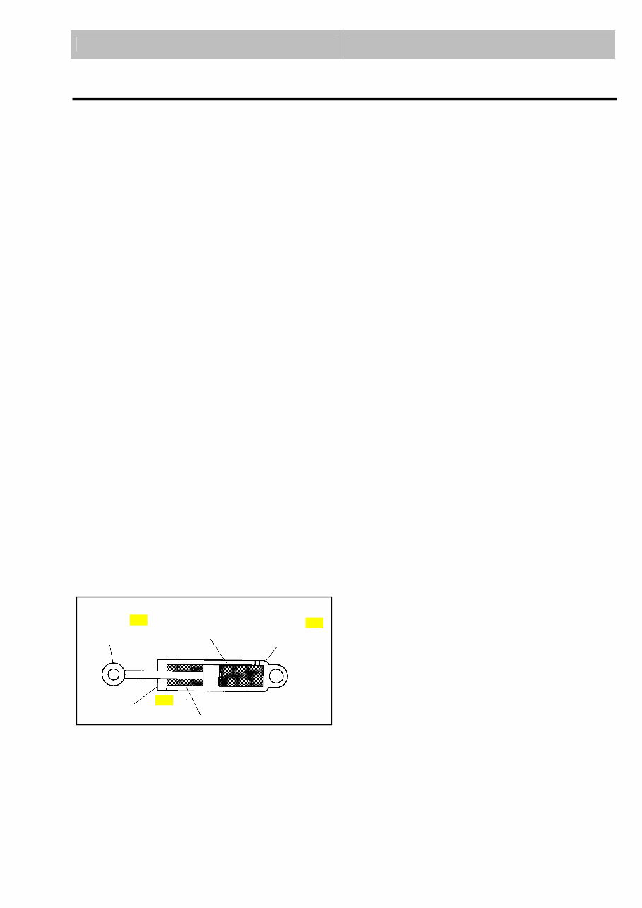
Hydraulic Cylinder
The terms for the cylinder have been decided as
follows:
Removal of Cylinder
When removing each cylinder, it is not required to
drain the hydraulic system. Only a small amount of
hydraulic oil in the oil passage between the
cylinder and control valve flows out. However,
when the control lever is not placed in the
NEUTRAL position, hydraulic oil will flow out of the
tank.
Bleeding Air from Hydraulic System
When a hose has been replaced, the hydraulic oil
has been changed, a cylinder has been removed
and other similar work has been performed, start
the engine, move the control levers to move the
working equipments to all positions and bleed air in
the hydraulic system. After making sure that the
hydraulic system operates properly, check the oil
level in the tank.
NOTE: Run the engine at low idle speed and, in
that condition, extend and retract each
cylinder about ten times. At this time, do
not move the cylinder to the stroke end.
When the engine is run at high idle speed
and each cylinder is moved to the stroke
end from the first, air in the cylinder may
damage the seals.
Cleaning the Hydraulic Brake System
Use the specified brake fluid. If other brake fluid is
used, a rubber part may be deteriorated and
swollen.
When adjusting the hydraulic brake system, take
care not to allow foreign material to get into the
brake fluid. To wash the master cylinder, wash in
general part washing agent and then wipe the
trace of solvent with denatured alcohol or brake
fluid. After that, dry the cylinder and take care not
to allow dirt and dust to adhere to the cylinder until
it is assembled. Wash rubber parts in denatured
alcohol or brake fluid. Do not use solvent of
petroleum series, such as gasoline, kerosene,
acetone, paint thinner, which will soften and swell a
rubber part.
Rod End (Part)
Cylinder Head (Part)
Tube End (Part)
Cylinder Bottom
(Chamber)
Rod (Chamber)
You're Reading a Preview
What's Included?
 Lifetime Access
Fast Download Speeds
Online & Offline Access
Access PDF Contents & Bookmarks
Full Search Facility
Print one or all pages of your manual
$71.99
HITACHI LX15-7 LX20-7 LX30-7 LX40-7 Wheel Loader Service Manual
Viewed 70 Times Today

What's Included?
Lifetime Access
Fast Download Speeds
Online & Offline Access
Access PDF Contents & Bookmarks
Full Search Facility
Print one or all pages of your manual
$71.99

Secure transaction
What's Included?
Lifetime Access
Fast Download Speeds
Online & Offline Access
Access PDF Contents & Bookmarks
Full Search Facility
Print one or all pages of your manual
Description
The HITACHI LX15-7 LX20-7 LX30-7 LX40-7 WHEEL LOADER SERVICE MANUAL is a comprehensive resource for both professional mechanics and DIY enthusiasts. It is organized into four parts:
- General Instructions: Safety during maintenance work and general cautionary instructions are compiled.
- Construction and Function: An explanation of the construction and function, including operation explanations through illustrations, circuit diagrams, and system diagrams.
- Overhaul: Methods of removing hydraulic equipment, disassembly and reassembly, adjusting methods, standard service values, and service limits are compiled.
- Troubleshooting: Probable causes and corrections for troubles are compiled.
The manual includes general information, construction and function, overhaul, troubleshooting/diagnosis, as well as electrical and hydraulic schematics. The total page count is 653 with a file size of 19Mb, and it is available in English language.
For any inquiries or if you are in search of a specific manual, feel free to reach out. Have a nice day!


