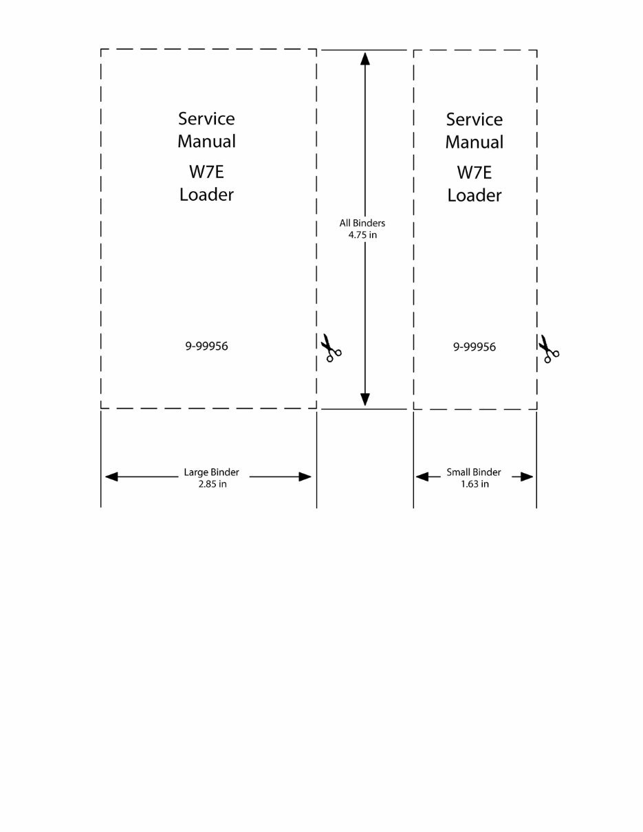
r---------, Service Manual W7E Loader 9-99956 All Binders 4.75 in r-----, Service Manual W7E Loader 9-99956 I L ________ .J _____ L ____ .J ...... ..- ___ Large Binder 2.85 in .- Small Binder --. 1.63 in
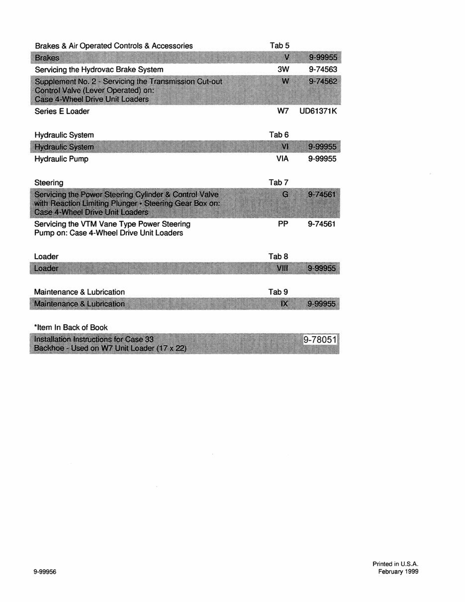
Brakes & Air Operated Controls & Accessories Servicing the Hydrovac Brake System Series E Loader Hydraulic System Hydraulic Pump Steering Servicing the VTM Vane Type Power Steering Pump on: Case 4-Wheel Drive Unit Loaders Loader Maintenance & Lubrication *Item In Back of Book 9-99956 Tab 5 3W 9-74563 W7 UD61371K Tab 6 VIA 9-99955 Tab 7 PP 9-74561 TabS Tab 9 Printed in U.S.A. February 1999
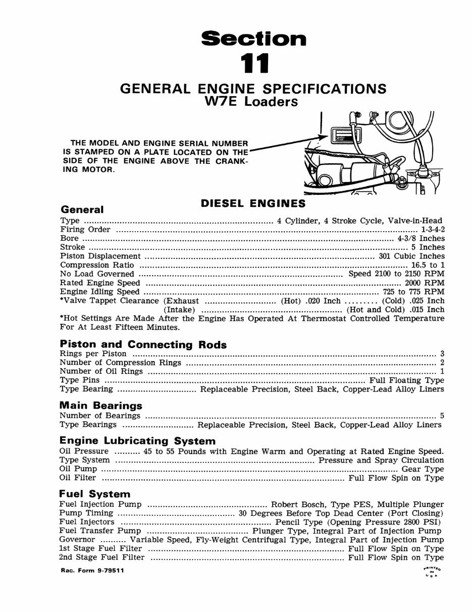
Section 11 GENERAL ENGINE SPECIFICATIONS W7E Loaders THE MODEL AND ENGINE SERIAL NUMBER IS STAMPED ON A PLATE LOCATED ON THE- SIDE OF THE ENGINE ABOVE THE CRANK- ING MOTOR. General DIESEL ENGINES Type .................................................................. ...... .. 4 Cylinder, 4 Stroke Cycle, Valve-in-Head Firing Order ........ ...................................... ................ .................... • ................................... 1-3-4-2 Bore ........................................................................ ................. ................................. 4-3/8 Inches Stroke .................... .. .............................. .................. ....................................................... 5 Inches Piston Displacement ... ........ ........................ .. .............. . ........... ........................... 301 Cubic Inches Compression Ratio .. ................................ ...................... ................................................. 16.5 to 1 No Load Governed ......................... ............. .......................... ......... .... ... Speed 2100 to 2150 RPM Rated Engine Speed .......... ............................... ........................ ................................... 2000 RPM Engine Idling Speed .................. .............. ........................ . ......... .......................... 725 to 775 RPM ·Valve Tappet Clearance (Exhaust .............. ........... ... (Hot) . 020 Inch ..... . ... (Cold) .025 Inch (Intake) ..... . .................. ............................... (Hot and Cold) . 015 Inch ·Hot Settings Are Made After the Engine Has Operated At Thermostat Controlled Temperature For At Least Fifteen Minutes. Piston and Connecting Rods Rings per Piston ........................ ............................................... .............. ............. .. ................... 3 Number of Compression Rings ................................... ........ ....................................................... 2 Number of Oil Rings . ........................................................................................... ..................... 1 Type Pins ........ ............................... ............... .. .. .. ............................... ........... Full Floating Type Type Bearing ....... ... ..................... Replaceable Precision, Steel Back, Copper-Lead Alloy Liners Main Bearings Number of Bearings ............... ................. ..................................................... .......................... ... 5 Type Bearings ............................ Replaceable Precision , Steel Back , Copper-Lead Alloy Liners Engine Lubricating System Oil Pressure .......... 45 to 55 Pounds with Engine Warm and Operating at Rated Engine Speed. Type System .............................. ........................ ........................ Pressure and Spray Circulation Oil Pump .. ........ ........................ .................. .............................................. .......... ........ Gear Type Oil Filter . .. .... ........................... ............................................................. Full Flow Spin on Type Fuel System Fuel Injection Pump ............................................... Robert Bosch, Type PES , Multiple Plunger Pump Timing .............................................. 30 Degrees Before Top Dead Center (Port Closing) Fuel Injectors ........................................................... Pencil Type (Opening Pressure 2800 PSI) Fuel Transfer Pump ........................................ Plunger Type, Integral Part of Injection Pump Governor .......... Variable Speed, Fly-Weight Centrifugal Type, Integral Part of Injection Pump 1st Stage Fuel Filter ............................. .. .............................................. Full Flow Spin on Type 2nd Stage Fuel Filter .............. .. ......................................... .. ................. Full Flow Spin on Type Rae. Form 9-79511
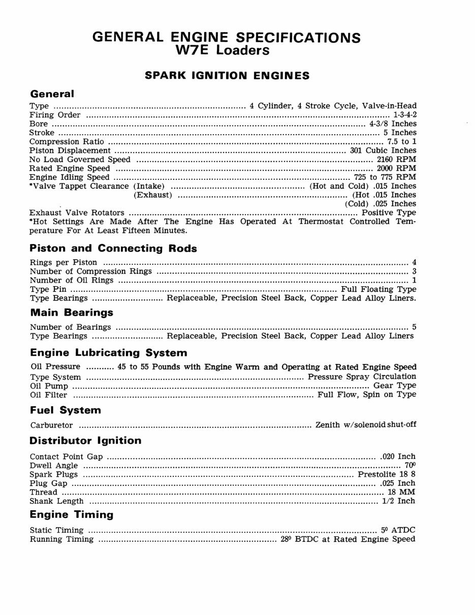
GENERAL ENGINE SPECIFICATIONS W7E Loaders SPARK IGNITION ENGINES General Type ........................................................................... 4 Cylinder, 4 Stroke Cycle, Valve-in-Head Firing Order .......................................................... . ........................................................... 1-3-4-2 Bore .......................... . ............................................................... . ............................... 4-3/8 Inches Stroke ................................................................................................ . ............................ 5 Inches Compression Ratio ........................................................................................................... 7.5 to 1 Piston Displacement ............................................................................ .............. 301 Cubic Inches No Load Governed Speed ............................. ... ............................................................ 2160 RPM Rated Engine Speed .............. ....... ................. . ........................................ ..................... 2000 RPM Engine Idling Speed ............................................................................................ 725 to 775 RPM ·Valve Tappet Clearance (Intake) .................................................... (Hot and Cold) .015 Inches (Exhaust) ........................................ , ....... .................. (Hot .015 Inches . (Cold) .025 Inches Exhaust Valve Rotators ................ ................................................... . ..................... Positive Type ·Hot Settings Are Made After The Engine Has Operated At Thermostat Controlled Tem- perature For At Least Fifteen Minutes. Piston and Connecting Rods Rings per Piston ......... ........ .... ...................... . ...................................... . .................................... 4 Number of Compression Rings ........................................................... . ...................................... 3 Number of Oil Rings ................................................................................................................. 1 Type Pin .................. ...................................................................................... Full Floating Type Type Bearings ............................ Replaceable, Precision Steel Back, Copper Lead Alloy Liners. Main Bearings Number of Bearings .................................................................................................................. 5 Type Bearings ............................ Replaceable, Precision Steel Back, Copper Lead Alloy Liners Engine Lubricating System Oil Pressure ........... 45 to 55 Pounds with Engine Warm and Operating at Rated Engine Speed Type System ..................................................................................... Pressure Spray Circulation Oil Pump .......................................................................... .. ........................................ Gear Type Oil Filter .............................................................................................. Full Flow, Spin on Type Fuel System Carburetor ........................................................................................... Zenith w / solenoid shut-off Distributor Ignition Contact Point Gap .......................................................................................................... 020 Inch Dwell Angle ........................................................................... ................................................. 7CfJ Spark Plugs .......................................................................................................... Prestolite 18 8 Plug Gap ........................................................................................................................ 025 Inch Thread .......................................... ...................................... . ............................................. 18 MM Shank Length ................................................................................ ................................. 1/ 2 Inch Engine Timing Static Timing ................................................................................................................. 50 ATDC Running Timing ...................................................................... 28 0 BTDC at Rated Engine Speed
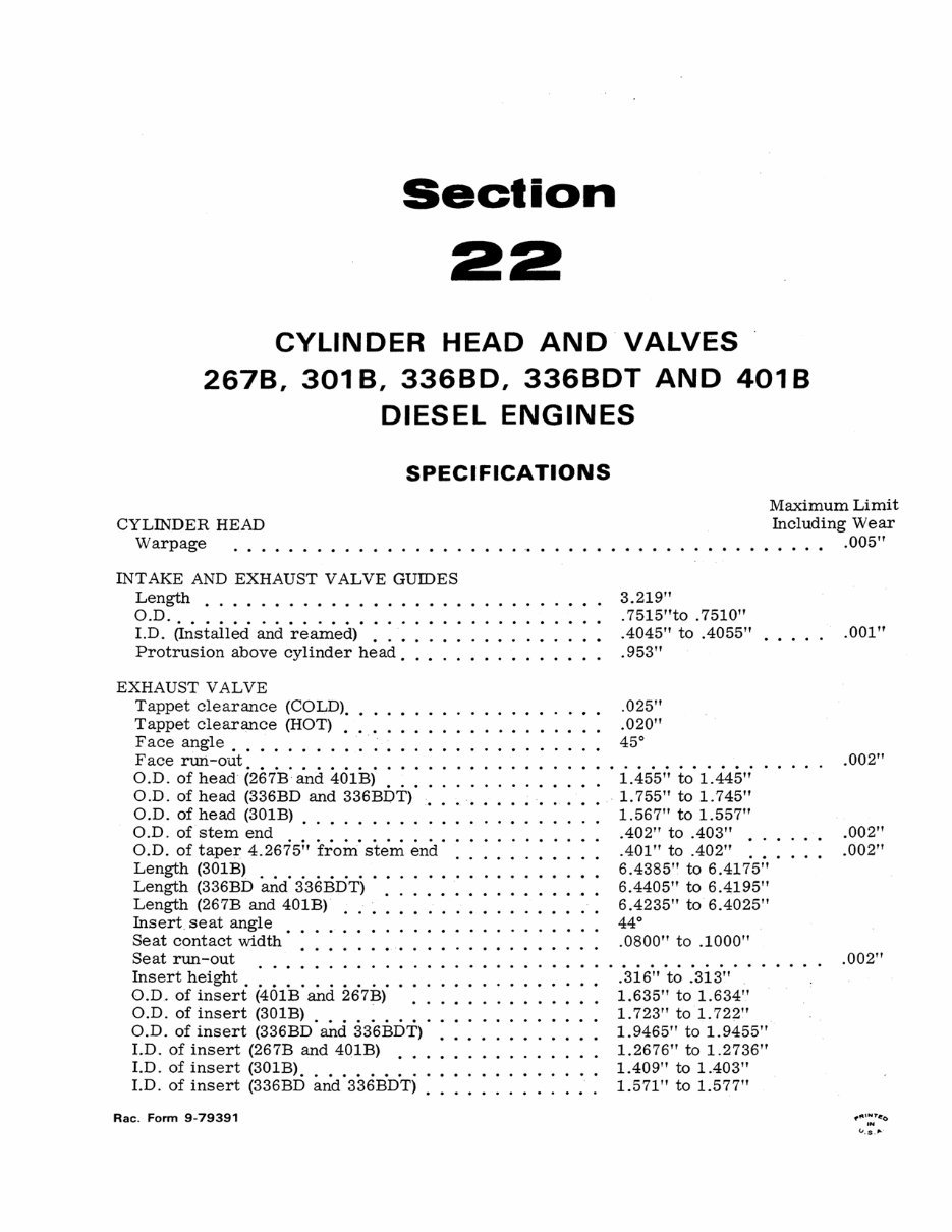
Section 22 CYLINDER HEAD AND"VALVES 2678, 3018, 33680, 3368DT AND 4018 DIESEL ENGINES SPECIFICATIONS CYLINDER HEAD Warpage Maximum Limit Including Wear INTAKE AND EXHAUST VALVE GUIDES Length ............ • ............. O.D .............. • ............. LD. (Installed and reamed) . . . . . . Protrusion above cylinder head. . . . . . . . . . . EXHAUST VALVE Tappet clearance (COLD) .... . Tappet clearance (HOT) ...... . Face angle. . . . . . . . .. . ... . F ace run -out O.D. of head (2EdB' and 401B)' : : : : : : : : : : : : . O.D. of head (336BD and 336BDT). . . . . . . . . O.D. of head (301B) ..... O.D. of stem end ........... . O.D. of taper 4.2675 i , fro in' end' : ..... . Length (301B) .. . . . . . . . . . . . . . . . . . . . . . . Length (336BD and 336BDT) . ........... . Length (267B and 401B) .. ............ . Insert seat angle . . . • . . . . . . Seat contact width' . . . . . . . . . . . . Seat run-out ... . ......... . Insert height . . . . . . . . . . . . . . . . . O.D. of insert (401B and 267B) ...• .... O.D. of insert (301B) ......... . O.D. of insert (336BD and 336BDT) ..... . LD. of insert (267B and 401B) ........ . LD. of insert (301B) .......... . LD. of insert (336BD and 336BDT). ....... . Rae . Form 9-79391 . . . . .. .005" 3.219" . 7515"to . 7510" .4045" to .4055" .953" .025" .020" 45° 1.455" to 1.445" " 1. 755" to 1. 7 45" 1.567" to 1.557" .402" to .403" . .401" to .402" ... 6.4385" to 6.4175" 6.4405" to 6.4195" 6.4235" to 6 .4025" 44° .0800" to .1000" .316" to .313" 1. 635" to 1. 634" 1. 723" to 1. 722" 1.9465" to 1.9455" 1.2676" to 1.2736" 1.409" to 1.403" 1.571" to 1.577" .001" .002" .002" .002" .002"
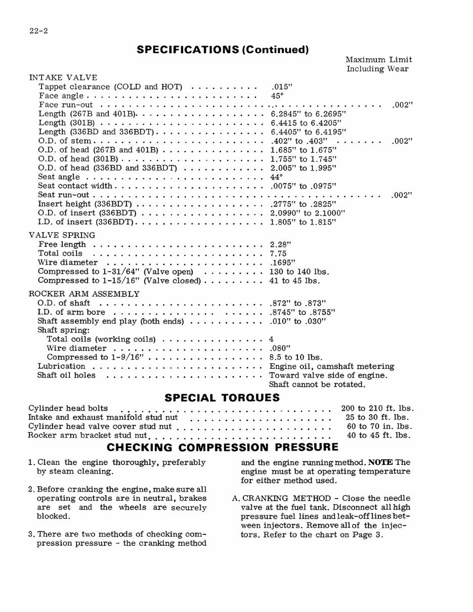
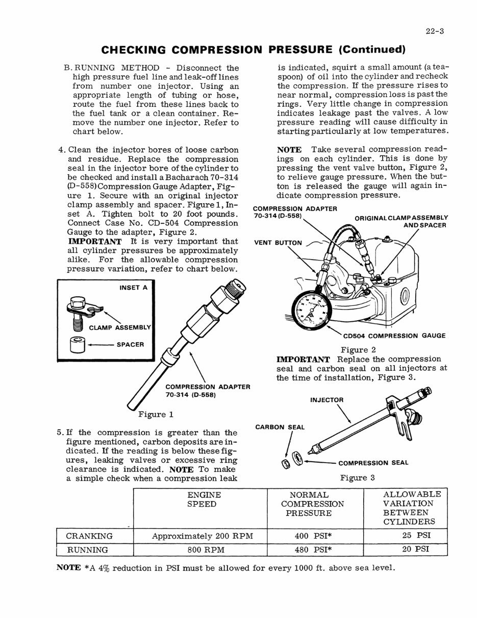
22-2 SPECIFICATIONS (Continued) INT AKE VALVE Tappet clearance (COLD and HOT) Face angle ....... . Face run-out ...... . Length (267B and 401B) .. Length (301B) ...... . Length (336BD and 336BDT). O.D. of stem ......... . O.D. of head (267B and 401B) . O.D. of head (301B) . . . .... O.D. of head (336BD and 336BDT) Seat angle ....... . Seat contact width. . . . . Seat run-out ....... . Insert height (336BDT) .. O.D. of insert (336BDT) I.D. of insert (336BDT). V ALVE SPRING Free length . . . • . . . Total coils ...... . Wire diameter • ............ Compressed to 1-31/64" (Valve open) . Compressed to 1-15/16" (Valve closed) . ROCKER ARM ASSEMBLY O.D. of shaft ....... •...• .... I.D. of arm bore • ...... • ..... • Shaft assembly end play (both ends) Shaft spring: Total coils (working coils) Wire diameter . . • . . . Compressed to 1-9/16" Lubrication . Shaft oil holes ..... . .015" 45 0 Maximum Limit Including Wear . .. . . . . . . . . . . . . . . . .002" 6.2845" to 6.2695" 6.4415 to 6.4205" 6.4405" to 6.4195" .402" to .403" 1.685" to 1.675" 1. 755" to 1. 745" 2.005" to 1.995" 44 0 .0075" to .0975" .2775" to .2825" 2.0990" to 2.1000" 1.805" to 1.815" 2.28" 7.75 .1695" 130 to 140 lbs. 41 to 45 lbs. .872" to .873" .8745" to .8755" .010" to .030" 4 .080" 8.5 to 10 lbs. .002" . 002" Engine oil, camshaft metering Toward valve side of engine. Shaft cannot be rotated. SPECIAL TORQUES Cylinder head bolts .•..•. Intake and exhaust manifold stud nut Cylinder head valve cover stud nut. Rocker arm bracket stud nut •.•.. 200 to 210 ft. lbs. 25 to 30 ft. lbs. 60 to 70 in. lbs. 40 to 45 ft. lbs. CHECKING COMPRESSION PRESSURE 1. Clean the engine thoroughly, preferably by steam cleaning. 2. Before cranking the engine, make sure all operating controls are in neutral, brakes are set and the wheels are securely blocked. 3. There are two methods of checking com- pression pressure - the cranking method and the engine running method. NOTE The engine must be at operating temperature for either method used. A. CRANKING METHOD - Close the needle valve at the fuel tank. Disconnect all high pressure fuel lines and leak-off lines bet- ween injectors. Remove all of the injec- tors. Refer to the chart on Page 3.
22-3 CHECKING COMPRESSION PRESSURE (Continued) B. RUNNING METHOD - Disconnect the high pressure fuel line and leak-off lines from number one injector. Using an appropriate length of tubing or hose, route the fuel from these lines back to the fuel tank or a clean container. Re- move the number one injector. Refer to chart below. 4. Clean the injector bores of loose carbon and residue. Replace the compression seal in the injector bore of the cylinder to be checked and install a Bacharach 70-314 (D-558) Compression Gauge Adapter, Fig- ure 1. Secure with an original injector clamp assembly and spacer. Figure 1, In- set A. Tighten bolt to 20 foot pounds. Connect Case No. CD-504 Compression Gauge to the adapter, Figure 2. IMPORTANT It is very important that all cylinder pressures be approximately alike. For the allowable compression pressure variation, refer to chart below. INSET A (21 __ u . SPACER COMPRESSION ADAPTER 70-314 (0-558) Figure 1 5. If the compression is greater than the figure mentioned, carbon deposits are in- dicated. If the reading is below these fig- ures, leaking valves or excessive ring clearance is indicated . NOTE To make a simple check when a compression leak ENGINE SPEED - CRANKING Approximately 200 RPM RUNNING 800 RPM is indicated, squirt a small amount (a tea- spoon) of oil into the cylinder and recheck the compression. If the pressure rises to near normal, compression loss is past the rings. Very little change in compression indicates leakage past the valves. A low pressure reading will cause difficulty in starting particularly at low temperatures. NOTE Take several compression read- ings on each cylinder. This is done by pressing the vent valve button, Figure 2, to relieve gauge pressure. When the but- ton is released the gauge will again in- dicate compression pressure. COMPRESSION ADAPTER 70-314 (0-558) I "CD504 GAUGE Figure 2 IMPORTANT Replace the compression seal and carbon seal on all injectors at the time of installation, Figure 3. CARBON SEAL , COMPRESSION SEAL Figure 3 NORMAL ALLOWABLE COMPRESSION VARIATION PRESSURE BETWEEN CYLINDERS 400 PSI* 25 PSI 480 PSI* 20 PSI NOTE * A 4% reduction in PSI must be allowed for every 1000 ft. above sea level.
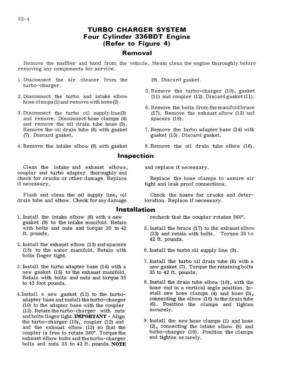
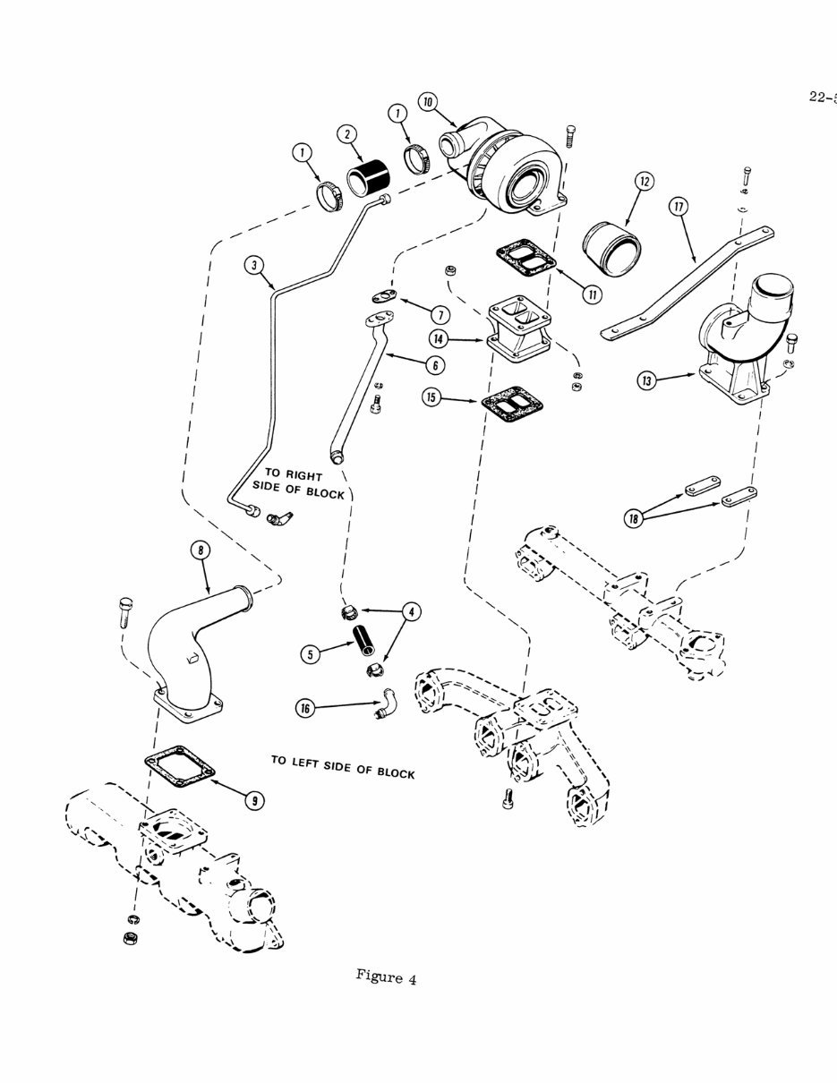
22-4 TURBO CHARGER SYSTEM Four Cylinder 336BDT Engine (Refer to Figure 4) Removal Remove the muffler and hood from the vehicle. Steam clean the engine thoroughly before removing any components for service. 1. Disconnect the air cleaner from the turbo-charger. 2. Disconnect the turbo and intake elbow hose clamps (1) and remove with hose (2) . 3. Disconnect the turbo oil supply line (3) and remove . Disconnect hose clamps (4) and remove the oil drain tube hose (5). Remove the oil drain tube (6) with gasket (7). Discard gasket. 4. Remove the intake elbow (8) with gasket (9). Discard gasket. 5. Remove the turbo-charger (10), gasket (11) and coupler (12). Discard gasket (11). 6. Remove the bolts from the manifold brace (17). Remove the exhaust elbow (13) and spacers (18). 7. Remove the turbo adapter base (14) with gasket (15). Discard gasket. 8. Remove the oil drain tube elbow (16). Inspection Clean the intake and exhaust elbows, coupler and turbo adapter thoroughly and check for cracks or other damage. Replace if necessary. Flush and clean the oil supply line, oil drain tube and elbow. Check for any damage and replace if necessary. Replace the hose clamps to assure air tight and leak proof connections. Check the hoses for cracks and deter- ioration. Replace if necessary. Installation 1. Install the intake elbow (8) with a new gasket (9) to the intake manifold. Retain with bolts and nuts and torque 35 to 42 ft. pounds . 2. Install the exhaust elbow (13) and spacers (18) to the water manifold. Retain with bolts finger tight. 3. Install the turbo adapter base (14) with a new gasket (15) to the exhaust manifold. Retain with bolts and nuts and torque 35 to 42 foot pounds. 4.Install a new gasket (11) to the turbo- adapter base and install the turbo-charger (10) to the adapter base with the coupler (12). Retain the turbo-charger with nuts and bolts finger tight. IMPORTANT - Align the turbo-charger (10), coupler (12) and and the exhaust elbow (13) so that the coupler is free to rotate 360 0 • Torque the exhaust elbow bolts and the turbo-charger bolts and nuts 35 to 42 ft. pounds. NOTE recheck that the coupler rotates 360 0 • 5. Install the brace (17) to the exhaust elbow (13) and retain with bolts. Torque 35 to 42 ft. pounds. 6. Install the turbo oil supply line (3) . 7. Install the turbo oil drain tube (6) with a new gasket (7). Torque the retaining bolts 35 to 42 ft. pounds. 8. Install the drain tube elbow (16), with the hose end in a vertical angle position. In- stall new hose clamps (4) and hose (5), connecting the elbow (16) to the drain tube (6) . Position the clamps and tighten securely. 9. Install the new hose clamps (1) and hose (2), connecting the intake elbow (8) and turbo-charger (10). Position the clamps and tighten se-Jurely.
I I I I " I I I I I I I I I ®- ---cD I I TO RIGHT \ SIDE I I I I OF BLOCK I I I I I I ( o Figure 4 I I I I J I 22-5
The Case W7E Wheel Loaders Repair Manual is a comprehensive guide designed to assist in the maintenance and repair of your equipment. Whether you are a professional mechanic or a DIY enthusiast, this workshop manual is a valuable resource for performing simple repairs or complete overhauls.
Inside this manual, you will find detailed instructions for the removal, installation, disassembly, and assembly of various components. The step-by-step guidance empowers you to confidently tackle any repair task with precision.
In addition to mechanical instructions, the manual also includes an electrical wiring diagram and hydraulic schematic, providing invaluable information to troubleshoot and diagnose electrical or hydraulic issues effectively.
Furthermore, the manual offers specifications and torque values, ensuring that you have all the necessary information to complete your repairs accurately and safely.


 Lifetime Access




