87728465 NA 1221E Tier 3 Wheel Loader 01Mar 08 First Edition REVISION HISTORY Remarks Issue Issue Date Applicable Machines This unit first became available 03-2008 Any use of editorial or pictorial content is strictly prohibited without express written permission from CNH America, LLC. Racine, WI 53403 U.S.A.. CNH America, LLC reserves the right to make improvements in design or changes in specifications at any time without incurring any obligation to install them on units previously sold. All data given in this publication is subject to production variations. Dimensions and weights are only approximate. Illustrations do not necessarily show products in standard condition.For exact information about any particular product, please consult your Dealer NOT FOR PRINT
WHEEL LOADER REPAIR MANUAL TABLE OF CONTENTS Section 1 - General Safety Hints ................................................................................................................. 1-1 Specification ................................................................................................................ 1-8 Operational Checkout Record Sheet ........................................................................... 1-20 Section 2 - Engine Structure And Function ................................................................................................ 2-1 Section 3 - Power Train System Structure And Function ................................................................................................ 3-1 Operational Checks And Troubleshooting ................................................................... 3-67 Tests And Adjustments ................................................................................................ 3-79 Disassembly And Assembly ........................................................................................ 3-82 Section 4 - Brake System Structure And Function ................................................................................................ 4-1 Operational Checks And Troubleshooting ................................................................... 4-19 Tests And Adjustments ................................................................................................ 4-25 Section 5 - Steering System Structure And Function ................................................................................................ 5-1 Operational Checks And Troubleshooting ................................................................... 5-19 Tests And Adjustments ................................................................................................ 5-26 Disassembly And Assembly ........................................................................................ 5-32 Section 6 - Work Equipment Structure And Function ................................................................................................ 6-1 Operational Checks And Troubleshooting ................................................................... 6-31 Tests And Adjustments ................................................................................................ 6-40 Disassembly And Assembly ........................................................................................ 6-54 Section 7 - Electrical System Component Location ................................................................................................... 7-1 Electronic Monitor System ........................................................................................... 7-23 Switches ...................................................................................................................... 7-36 Electrical Component Specification ............................................................................. 7-43 Connectors .................................................................................................................. 7-49 Troubleshooting ........................................................................................................... 7-69 NOT FOR PRINT
WHEEL LOADER REPAIR MANUAL NOTES NOT FOR PRINT
0-1 87728465 NA Issued 03-2008 Bur SECTION 0 - FOREWORD 1. STRUCTURE This service manual has been prepared as an aid to improve the quality of repairs by giving the serviceman an accurate understanding of the product and by showing him the correct way to perform repairs and make judgements. Make sure you understand the contents of this manual and use it to full effect at every opportunity. This service manual mainly contains the necessary technical information for operations performed in a service workshop. For ease of understanding, the manual is divided into the following sections. Structure and function This group explains the structure and function of each component. It serves not only to give an understanding of the structure, but also serves as reference material for troubleshooting. Operational checks and troubleshooting This group explains the system operational checks and troubleshooting charts correlating problem to remedy. Tests and adjustments This group explains checks to be amide before and after performing repairs, as well as adjustments to be made at completion of the checks and repairs. Disassembly and assembly This section explains the order to be followed when removing, installing, disassembling or assembling each component, as well as precautions to be taken for these operations. The specifications contained in this shop manual are subject to change at any time and without any advance notice. Contact your CASE distributor for the latest information. NOT FOR PRINT
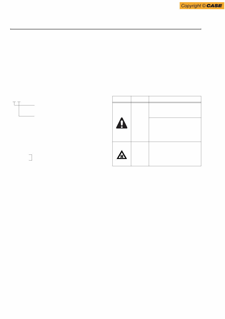
0-2 Issued 03-2008 Bur 87728465 NA SECTION 0 - FOREWORD 2. HOW TO READ THE SERVICE MANUAL Distribution and updating Any additions, amendments or other changes will be sent to CASE distributors. Get the most up-to-date information before you start any work. Filing method 1. See the page number on the bottom of the page. File the pages in correct order. 2. Following examples shows how to read the page number. Example 1 3. Additional pages : Additional pages are indicated by a hyphen (-) and number after the page number. File as in the example. Revised edition mark (---------------) When a manual is revised, an edition mark is recorded on the bottom outside corner of the pages. Revisions Revised pages are shown at the list of revised pages on the between the contents page and section 1 page. Symbols So that the service manual can be of ample practical use, important places for safety and quality are marked with the following symbols. 3 - 3 Section number (3. Power train system) Consecutive page number for each section 10 - 4 10 - 4 - 1 10 - 4 - 2 10 - 5 Added pages Symbol Item Remarks Safety Special safety precautions are necessary when performing the work. Extra special safety precautions are necessary when performing the work because it is under internal pressure. Caution Special technical precautions or other precautions for preserving standards are necessary when performing the work. ①②③… NOT FOR PRINT
0-3 87728465 NA Issued 03-2008 Bur SECTION 0 - FOREWORD 3. CONVERSION TABLE Method of using the Conversion Table. The Conversion Table in this section is provided to enable simple conversion of figures. For details of the method of using the Conversion Table, see the example given below. Example 1. Method of using the Conversion Table to convert from millimeters to inches. Convert 55mm into inches. (1) Locate the number 50 in the vertical column at the left side, take this as ’a’, then draw a horizontal line from ’a’. (2) Locate the number 5 in the row across the top, take this as ’b’, then draw a perpendicular line down from ’b’. (3) Take the point where the two lines cross as ’c’. This point ’c’ gives the value when converting from millimeters to inches. Therefore, 55mm = 2.165 inches. 2. Convert 550mm into inches. (1) The number 550 does not appear in the table, so divide by 10 (Move the decimal point one place to the left) to convert it to 55mm. (2) Carry out the same procedure as above to convert 55mm to 2.165 inches. (3) The original value (550mm) was divided by 10, so multiply 2.165 inches by 10 (Move the decimal point one place to the right) to return to the original value. This gives 550mm = 21.65 inches. Millimeters to inches 1mm = 0.03937 in 0 1 2 3 4 5 6 7 8 9 0 0.039 0.079 0.118 0.157 0.197 0.236 0.276 0.315 0.354 10 0.394 0.433 0.472 0.512 0.551 0.591 0.630 0.669 0.709 0.748 20 0.787 0.827 0.866 0.906 0.945 0.984 1.024 1.063 1.102 1.142 30 1.181 1.220 1.260 1.299 1.339 1.378 1.417 1.457 1.496 1.536 40 1.575 1.614 1.654 1.693 1.732 1.772 1.811 1.850 1.890 1.929 50 1.969 2.008 2.047 2.087 2.126 2.165 2.205 2.244 2.283 2.323 60 2.362 2.402 2.441 2.480 2.520 2.559 2.598 2.638 2.677 2.717 70 2.756 2.795 2.835 2.874 2.913 2.953 2.992 3.032 3.071 3.110 80 3.150 3.189 3.228 3.268 3.307 3.346 3.386 3.425 3.465 3.504 90 3.543 3.583 3.622 3.661 3.701 3.740 3.780 3.819 3.858 3.898 b c a NOT FOR PRINT
The Case 1221E Wheel Loaders Repair Manual is a comprehensive guide for repairing and maintaining your Case 1221E Wheel Loader. Whether you are a professional mechanic or a do-it-yourself enthusiast, this workshop manual will be your go-to resource.
This repair manual provides detailed instructions for removal, installation, disassembly, and assembly of various components of the Case 1221E Wheel Loader. It also features an electrical wiring diagram and hydraulic schematic, allowing for easy troubleshooting and diagnosis of any electrical or hydraulic issues.
With the Case 1221E Wheel Loaders Repair Manual, you will have access to important specifications and torque values, ensuring that all repairs and maintenance tasks are performed correctly and safely.











 Lifetime Access




