ASV RC30 Rubber Track Loader Service Repair Manual
What's Included?
Lifetime Access
Fast Download Speeds
Online & Offline Access
Access PDF Contents & Bookmarks
Full Search Facility
Print one or all pages of your manual
A Caterpillar Affiliate ASVSP001 (06/01) Part Number: 0304-820 Service Manual RC RC RC RC-30 30 30 30 All Surface Loader All Surface Loader All Surface Loader All Surface Loader
i Table of Contents 1. Product Safety Chapter Overview................................................... 1-1 Safety Messages .................................................... 1-1 Information Messages ............................................ 1-1 Basic Precautions ................................................... 1-1 Safety Signs ...................................................... 1-1 Protective Equipment ........................................ 1-2 Mounting and Dismounting ............................... 1-2 Lifting ................................................................ 1-2 Hot Fluids and Parts.......................................... 1-2 Corrosion Inhibitor ............................................. 1-2 Batteries ............................................................ 1-2 Pressurized Items ............................................. 1-2 Repair ..................................................................... 1-3 Work Tools ............................................................. 1-3 Asbestos Information.............................................. 1-4 Machine Labels and Decals ................................... 1-4 Product ID Number ........................................... 1-4 Machine Label and Decal Examples ................. 1-5 2. Technical Specifications Chapter Overview................................................... 2-1 Specifications ......................................................... 2-1 Engine ............................................................... 2-1 Transmission..................................................... 2-1 Drive Motors ...................................................... 2-1 Control Handles ................................................ 2-1 Auxiliary Pump .................................................. 2-1 Loader Valve ..................................................... 2-1 Cooler ............................................................... 2-1 3. System Diagrams Chapter Overview................................................... 3-1 Filtering and Cooling System.................................. 3-1 Auxiliary Circuit System.......................................... 3-2 Drive Loop System ................................................. 3-3 4. Machine Controls and Instrumentation Chapter Overview................................................... 4-1 Machine Controls.................................................... 4-1 Loader Control .................................................. 4-1 Drive Control ..................................................... 4-1 Throttle .............................................................. 4-1 Dash Panel ............................................................. 4-1 Gauge/Warning Light Panel ................................... 4-2 5. Operator Enclosure Disassembly and Assembly Chapter Overview................................................... 5-1 Personal Safety ...................................................... 5-1 Machine Preparation .............................................. 5-1 Preliminary Checkout ............................................. 5-1 Operator Enclosure Disassembly and Assembly Procedures ............................................................. 5-1 Light Bar Removal and Installation ......................... 5-1 Light Bar Removal............................................. 5-1 Light Bar Installation.......................................... 5-2 Ignition Switch Removal and Installation ................ 5-2 Ignition Switch Removal .................................... 5-2 Ignition Switch Installation................................. 5-3 Console Gauge/Warning Panel Removal and Installation .............................................................. 5-4 Console Gauge Removal .................................. 5-4 Console Gauge Installation ............................... 5-4 Lap Bar Gas Assist Spring Removal and Installation ....................................................... 5-5 Lap Bar Gas Assist Spring Removal ................. 5-5 Lap Bar Gas Assist Spring Installation .............. 5-5 6. Chassis Disassembly and Assembly Chapter Overview................................................... 6-1 Personal Safety ...................................................... 6-1 Machine Preparation .............................................. 6-1 Preliminary Checkout ............................................. 6-1 Chassis Disassembly and Assembly Procedures ............................................................. 6-1 Seat Removal and Installation................................ 6-1 Seat Removal ................................................... 6-1 Seat Installation ................................................ 6-2 Fuel Sending Unit Removal and Installation........... 6-2 Fuel Sending Unit Removal .............................. 6-3 Fuel Sending Unit Installation ........................... 6-4 Fuel Tank Removal and Installation ...................... 6-4 Fuel Tank Removal ........................................... 6-4 Fuel Tank Installation ........................................ 6-6 7. Radiator/Oil Cooler Disassembly and Assembly Chapter Overview................................................... 7-1 Personal Safety ...................................................... 7-1 Machine Preparation .............................................. 7-1 Preliminary Checkout ............................................. 7-1 Radiator/Oil Cooler Disassembly and Assembly Procedures ............................................................. 7-1 Fan Guard Removal and Installation ...................... 7-1 Fan Guard Removal .......................................... 7-2 Fan Guard Installation....................................... 7-2 Fan and Fan Shroud Removal and Installation ...... 7-2 Fan and Fan Shroud Removal .......................... 7-2 Fan and Fan Shroud Installation ....................... 7-3 Radiator/Cooler Removal and Installation .............. 7-4 Radiator/Cooler Removal .................................. 7-4 Radiator/Cooler Installation............................... 7-6 Radiator/Oil Cooler Adjustment Procedures.......... 7-7 Fan Shroud Adjustment .................................... 7-7 Fan Guard Adjustment ...................................... 7-8 8. Hydraulic Reservoir Disassembly and Assembly Chapter Overview................................................... 8-1 Personal Safety ...................................................... 8-1 Machine Preparation .............................................. 8-1 Preliminary Checkout ............................................. 8-1 Hydraulic Reservoir Disassembly and Assembly Procedures ............................................................. 8-1 Filter Element Removal and Installation ................. 8-1
All Surface Loader Table of Contents ii Filter Assembly Removal and Installation ............... 8-1 Filter Assembly Removal .................................. 8-2 Filter Assembly Installation ............................... 8-3 Filler Cap Assembly Removal and Installation ....... 8-4 Filler Cap Assembly Removal ........................... 8-4 Filler Cap Assembly Installation ........................ 8-5 Access Cover Removal and Installation ................. 8-5 Access Cover Assembly Removal .................... 8-6 Access Cover Assembly Installation ................. 8-6 Reservoir Gauge Removal and Installation ............ 8-7 Reservoir Gauge Removal ................................ 8-7 Reservoir Gauge Installation ............................. 8-8 Suction Screen Removal and Installation ............... 8-8 Suction Screen Removal ................................... 8-8 Suction Screen Installation................................ 8-9 Hydraulic Reservoir Cleaning Procedures ............. 8-9 Hydraulic Reservoir Cleaning............................ 8-9 9. Loader/Transmission Controls Disassembly and Assembly Chapter Overview................................................... 9-1 Personal Safety ...................................................... 9-1 Machine Preparation .............................................. 9-1 Preliminary Checkout ............................................. 9-1 Loader/Transmission Controls Disassembly and Assembly Procedures............................................. 9-1 Loader Control Joystick/Drive Control Joystick Removal and Installation ........................................ 9-1 Loader Control Joystick/Drive Control Joystick Removal ............................................................ 9-2 Loader Control Joystick/Drive Control Joystick Installation ......................................................... 9-3 Loader Float Magnet Removal and Installation ...... 9-4 Loader Float Magnet Removal .......................... 9-4 Loader Float Magnet Installation ....................... 9-6 Loader Valve Removal and Installation ................. 9-7 Loader Valve Removal ...................................... 9-7 Loader Valve Installation ................................... 9-9 10. Transmission and Drive Disassembly and Assembly Chapter Overview................................................. 10-1 Personal Safety .................................................... 10-1 Machine Preparation ............................................ 10-1 Preliminary Checkout ........................................... 10-1 Transmission and Drive Disassembly and Assembly Procedures.................................... 10-1 Brake Cylinder Removal and Installation .............. 10-1 Drive Motor Removal and Installation................... 10-1 Auxiliary Gear Pump Removal and Installation .... 10-2 Auxiliary Gear Pump Removal ........................ 10-2 Auxiliary Gear Pump Installation ..................... 10-3 Tandem Pump Removal and Installation .............. 10-4 Tandem Pump Removal ................................. 10-4 Tandem Pump Installation .............................. 10-5 Pump Drive Coupler Removal and Installation ..... 10-6 Pump Drive Coupler Removal ......................... 10-6 Pump Drive Coupler Installation...................... 10-7 11. Engine Components Disassembly and As- sembly Chapter Overview................................................. 11-1 Personal Safety .................................................... 11-1 Machine Preparation ............................................ 11-1 Preliminary Checkout ........................................... 11-1 Engine Components Disassembly and Assembly Procedures .......................................... 11-1 Primary Air Filter Removal and Installation........... 11-1 Safety Air Filter Removal and Installation............. 11-1 Engine Oil Filter Removal and Installation............ 11-1 Fuel Filter Removal and Installation .................... 11-2 Muffler Removal and Installation ......................... 11-2 Muffler Removal .............................................. 11-2 Muffler Installation ........................................... 11-2 Exhaust Pipe Removal and Installation ................ 11-3 Exhaust Pipe Removal .................................... 11-3 Exhaust Pipe Installation................................. 11-4 Battery Removal and Installation .......................... 11-5 Battery Removal ............................................. 11-5 Battery Installation .......................................... 11-6 Bleeding the Fuel System………………………….11-7 12. Undercarriage Disassembly and Assembly Chapter Overview................................................. 12-1 Personal Safety .................................................... 12-1 Machine Preparation ............................................ 12-1 Preliminary Checkout ........................................... 12-1 Undercarriage Disassembly and Assembly Procedures ........................................................... 12-1 Wheel Removal and Installation .......................... 12-1 Wheel Removal............................................... 12-2 Wheel Installation............................................ 12-3 Sprocket Roller Removal and Installation............ 12-3 Sprocket Roller Removal ................................ 12-4 Sprocket Roller Installation ............................. 12-4 Brake Removal and Installation ........................... 12-4 Brake Removal ............................................... 12-5 Brake Installation ............................................ 12-5 Track Removal and Installation ........................... 12-6 Track Removal ................................................ 12-6 Track Installation ............................................. 12-8 Sprocket Bearing Plate Removal and Installation ............................................................ 12-9 Sprocket Bearing Plate Removal .................... 12-9 Sprocket Bearing Plate Installation ............... 12-11 Sprocket Removal and Installation .................... 12-12 Sprocket Removal......................................... 12-12 Sprocket Installation...................................... 12-13 Drive Motor Removal and Installation................ 12-13 Drive Motor Removal .................................... 12-13 Drive Motor Installation ................................. 12-14 13. Loader Disassembly and Assembly Chapter Overview................................................. 13-1 Personal Safety .................................................... 13-1 Machine Preparation ............................................ 13-1 Preliminary Checkout ........................................... 13-1 Loader Disassembly and Assembly Procedures . 13-1 Lift Cylinder/Tilt Cylinder Removal and Installation ..................................................... 13-1 Lift Cylinder/Tilt Cylinder Removal .................. 13-1 Lift Cylinder/Tilt Cylinder Installation ............... 13-3
Index-1 Index A Access Cover Removal and Installation ................................... 8-5 Air Filter Change Procedures ................................................. 16-3 Asbestos Information ............................................................... 1-4 Auxiliary Circuit System ........................................................... 3-2 Auxiliary Gear Pump Removal and Installation....................... 10-2 B Battery Removal and Installation............................................ 11-5 Brake Removal and Installation.............................................. 12-4 C Chassis Disassembly and Assembly ........................................ 6-1 Console Gauge/Warning Panel Removal and Installation ........ 5-4 D Dash Panel .............................................................................. 4-1 Drive Control ............................................................................ 4-1 Drive Control Joystick Removal and Installation ....................... 9-1 Drive Loop System................................................................... 3-3 Drive Motor Removal and Installation................................... 12-13 E Engine Components Disassembly and Assembly................... 11-1 Engine Oil Filter Removal and Installation .............................. 11-1 Engine Oil Specifications ....................................................... 16-1 Exhaust Pipe Removal and Installation .................................. 11-3 F Fan and Fan Shroud Removal and Installation......................... 7-2 Fan Guard Removal and Installation ........................................ 7-1 Filler Cap Assembly Removal and Installation.......................... 8-4 Filter Assembly Removal and Installation ................................. 8-1 Filter Element Removal and Installation ................................... 8-1 Filtering and Cooling System ................................................... 3-1 Fuel Filter Change Procedures .............................................. 16-3 Fuel Sending Unit Removal and Installation ............................. 6-2 Fuel, Bleeding……………………………………………………...11-7 Fuel Specifications ................................................................. 16-3 Fuel Tank Removal and Installation ......................................... 6-4 Fuse Box ............................................................................... 16-4 G Gauge/Warning Light Panel ..................................................... 4-2 Grease Fittings ...................................................................... 16-5 H Hydraulic Fluid and Filter Change Procedures ....................... 16-2 Hydraulic Reservoir Disassembly and Assembly...................... 8-1 Hydraulic Reservoir Cleaning Procedures ................................ 8-9 Hydraulic Pressure Check & Adjustment……………………….17-1 I Ignition Switch Removal and Installation .................................. 5-2 Information Messages.............................................................. 1-1 L Lap bar Gas Assist Spring Removal and Installation ................ 5-5 Latch Pin Assembly Removal and Installation ........................ 14-1 Lift Cylinder Removal and Installation .................................... 13-1 Light Bar Removal and Installation ........................................... 5-1 Loader Control Joystick Removal and Installation .................... 9-1 Loader Control ......................................................................... 4-1 Loader Disassembly and Assembly Procedures..................... 13-1 Loader Float Magnet Removal and Installation ......................... 9-4 Loader Valve Removal and Installation..................................... 9-7 Loader/Transmission Controls Disassembly and Assembly ...... 9-1 Low-Flow Relief Valve Removal and Installation..................... 13-5 M Machine Controls and Instrumentation ..................................... 4-1 Machine Labels and Decals...................................................... 1-4 Maintenance Schedule ........................................................... 16-1 Muffler Removal and Installation............................................. 11-2 O Oil Change Procedures .......................................................... 16-1 Operator Enclosure Disassembly and Assembly....................... 5-1 P Primary Air Filter Removal and Installation ............................. 11-1 Pump Drive Coupler Removal and Installation ........................ 10-6 Q Quick Attach Assembly Removal and Installation ................... 14-3 R Radiator/Cooler Removal and Installation ................................. 7-4 Radiator/Oil Cooler Adjustment Procedures.............................. 7-7 Reservoir Gauge Removal and Installation ............................... 8-7 S Safety Air Filter Removal and Installation ............................... 11-1 Safety Messages ...................................................................... 1-1 Safety Precautions ................................................................... 1-1 Seat Removal and Installation .................................................. 6-1 Specifications ........................................................................... 2-1 Sprocket Bearing Plate Removal and |Installation................... 12-9 Sprocket Removal and Installation........................................ 12-12 Sprocket Roller Removal and Installation ............................... 12-3 Suction Screen Removal and Installation.................................. 8-8 System Diagrams ..................................................................... 3-1 T Tandem Pump Removal and Installation ................................ 10-4 Throttle ..................................................................................... 4-1 Tilt Cylinder Removal and Installation ..................................... 13-1 Track Removal and Installation............................................... 12-6 Track Tension Adjustment Procedures ................................... 16-4 Transmission and Drive Disassembly and Assembly .............. 10-1 Troubleshooting...................................................................... 15-1 U Undercarriage Disassembly and Assembly............................. 12-1 W Wheel Removal and Installation ............................................. 12-1
ASV, Inc 840 Lily lane P.O. Box 5160 Grand Rapids, MN 55744 ASV Parts & Service Phone: 800-346-4367 ASV Parts & Service Fax: 218-327-2297 www.asvi.com A Caterpillar Affiliate ASVSP001 (06/01) Copyright 2001, ASV Inc. Printed in U.S.A.
2-1 2. Technical Specifications Specifications Engine − Model: Cat 3013 − Displacement: 1.5 liter − Gross horsepower: 31.5 hp (23.5 kW) − Torque: 64.39 lb-ft (87.3 Nm) − Idle rpm: 2800 (high idle); 1175 (low idle) − Hot water temperature sender: 217°F (102.7°C) − Average water /thermostat temperature: 190°F (87.8°C) Transmission − Model: Cat AA10VG18 tandem (Rexroth) Drive pumps − Displacement: 1.098 in 3 /rev (18.0 cc/rev) − Relief pressure: 3800 psi (26,200 kPa) − Flow: 13 gpm (11.4 lpm) @ 2800 rpm (high idle) Charge pumps (2) − Displacement: 0.33 in 3 /rev (5.4 cc/rev) X 2 − Relief pressure: Serial Number RSA001 through RSA01056, 450 to 500 psi (2620- 2758 kPa) at high idle with warm oil, Serial Number RSA01057 and higher 340 to 380 psi at high idle with warm oil. − Flow: a. 3 gpm (11.4 lpm) combined @ 1175 rpm (low idle) b. 7.8 gpm (29.5 lpm) combined @ 2800 rpm (high idle) Drive Motors − Model: Eaton/Charlynn 4000 light series − Displacement: 19.8 in 3 /rev (324.5 cc/rev) − Shuttle control: 0.046-in fitting orifices allow 1 gpm per side @ idle with 130°F (54.4°C) oil Control Handles − Model: CAT 4TH6 Auxiliary Pump − Model: Rexroth − Displacement: 0.87 in 3 /rev (114.3 cc/rev) − Flow: 10 gpm (37.8 lpm) @ 2800 rpm (high idle) − Relief pressure: 3000 psi (20,684 kPa) − Cooling/filtering: Auxiliary oil is filtered and cooled at all times. In Auxiliary mode, the oil is filtered after the attachment to protect the ma- chine if the attachment motor fails or contami- nants are introduction from the quick couplers. Loader Valve − Model: Husko − Relief pressure: 3000 psi (20,684 kPa) − Pilot pressure required to move spools: 180- 220 psi (1241-1517 kPa) Cooler − Burst pressure: 400 psi (2757 kPa) − Operating pressure: 250 psi (1724 kPa) − Bypass relief pressure: 100 psi (689 kPa) − Average oil temperature: a. 50°F (10°C) above ambient in general ap- plication b. 80°F (26.6°C) above ambient in extreme application − Hot oil sending unit: 225°F (107.2°C) Critical Torque Specs − Drive Sprocket Retainer Bolt o 85 ft-lb. w/Blue Loctite − Transmission Mounting Bolts o 80 ft-lb. w/Blue Loctite − Drive Sprocket Drive Teeth Bolts o 110 ft-lb. -Dry − Bogie Wheel Retaining Nut o 80 ft-lb. -Dry
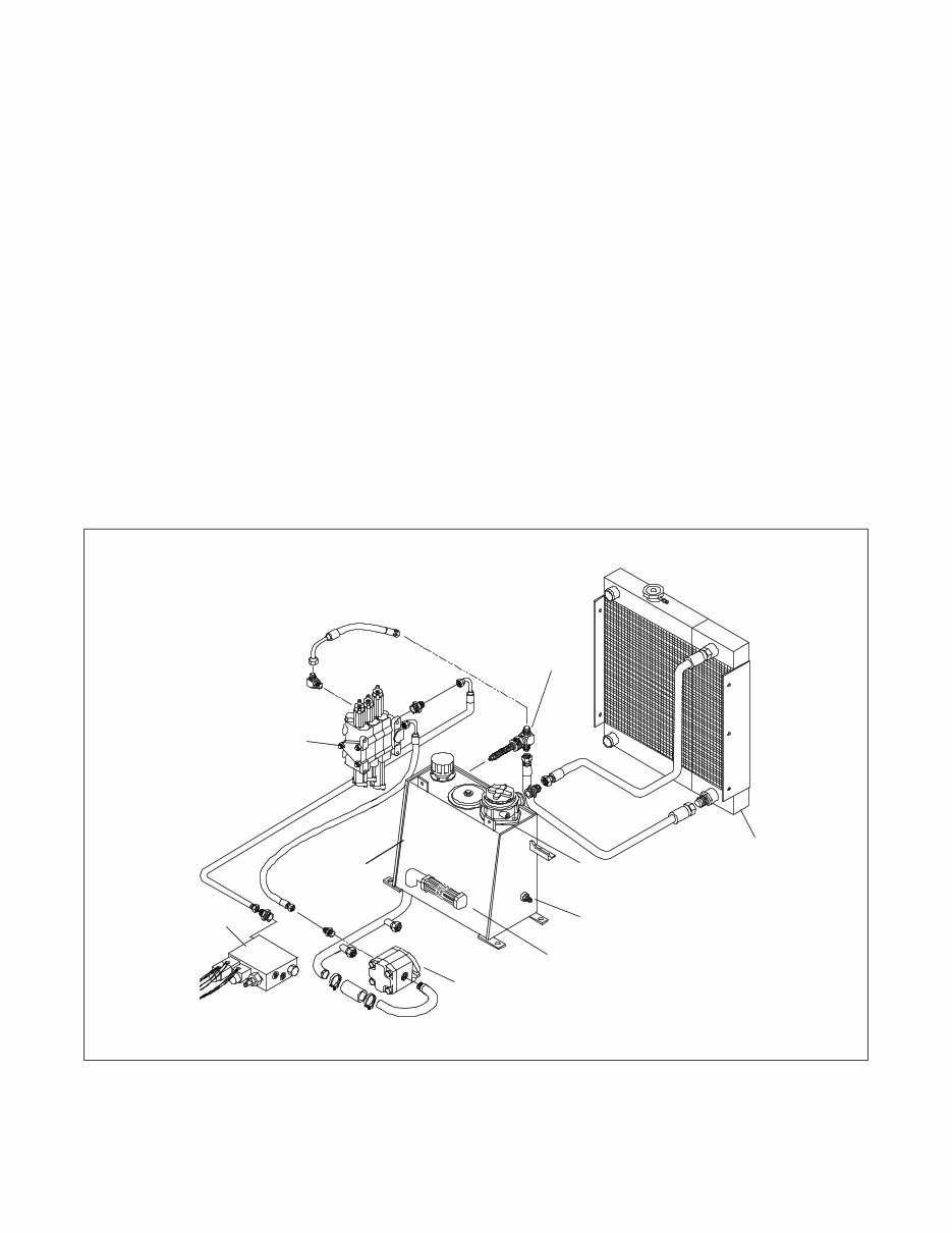
3-1 3. System Diagrams Chapter Overview This chapter contains diagrams for the following All Surface Loader systems. • Filtering and cooling system • Auxiliary circuit system • Drive loop system Filtering and Cooling System The filtering and cooling system (Figure 3-1) con- tains the following major components. • Hydraulic reservoir • Radiator/oil cooler • Loader valve • Auxiliary gear pump • Pilot control manifold Figure 3-1 Filtering and Cooling System 3-001 50-Micron Suction Screen 10-Micron Return Filter Hot Oil Temp Sending Unit 100 PSI Cooler Relief Radiator/Oil Cooler Loader Valve Hydraulic Reservoir Auxiliary Gear Pump Pilot Control Manifold
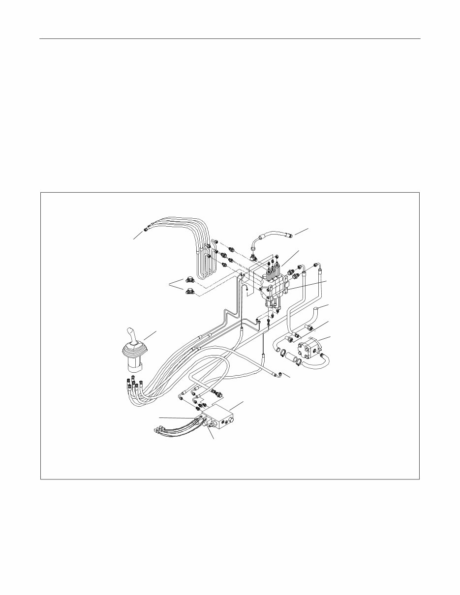
All Surface Loader 3. System Diagrams 3-2 Auxiliary Circuit System The auxiliary circuit system (Figure 3-2) contains the following major components. • Loader valve • Pilot control manifold • Auxiliary gear pump • Loader control joystick Figure 3-2 Auxiliary Circuit System 3-002 To Cooler Then to Tank Loader Loader Control Joystick Quick Couplers Loader Valve Relief Valve Tranny Aux Gear Pump Reservoir Pilot Control Manifold Operator Pressure Solenoid Aux Flow Solenoids Reservoir
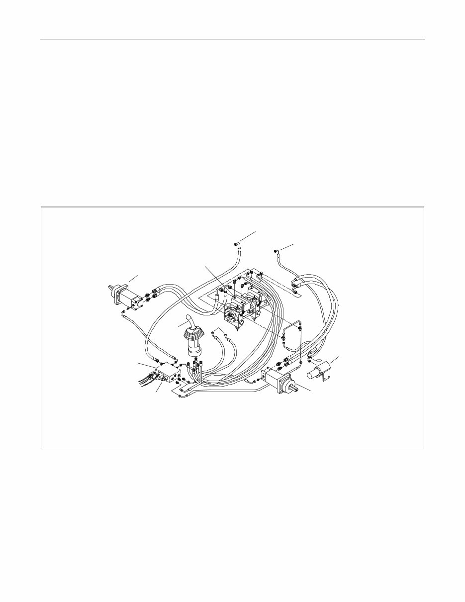
All Surface Loader 3. System Diagrams 3-3 Drive Loop System The drive loop system (Figure 3-3) contains the fol- lowing major components. • Tandem pump • Drive motors • Pilot control manifold • Brake cylinders • Drive control joystick Figure 3-3 Drive Loop System 3-003 To Implement Valve To Tank Brake Cylinder Drive Motor Pilot Control Manifold Charge Pressure Test Port Drive Control Joystick To Tank Tandem Pump (With Drive & Charge Pressure Relief Valves) Drive Motor
This Service Repair Manual is the ultimate resource for the ASV RC-30 Rubber Track Loader. It encompasses service and repair procedures, assembly and disassembly instructions, wiring diagrams, and comprehensive technical details.
The Service Manual covers a wide range of topics including product safety, technical specifications, system diagrams, machine controls and instrumentation, operator enclosure disassembly and assembly, chassis disassembly and assembly, radiator/oil cooler disassembly and assembly, hydraulic reservoir disassembly and assembly, loader/transmission controls disassembly and assembly, transmission and drive disassembly and assembly, engine components disassembly and assembly, undercarriage disassembly and assembly, loader disassembly and assembly, quick attach disassembly and assembly, troubleshooting, maintenance, and hydraulic pressure check & adjustment.
In addition to the Service Manual, this package also includes a Parts Manual and an Operations Manual.
File Format: PDF
Language: English
Compatibility: All Versions of Windows, Mac, and Linux
Requirements: Adobe Reader, Win
Recently Viewed
5,521,897Happy Clients
2,594,462eManuals
1,120,453Trusted Sellers
15Years in Business
Price:
Actual Price:
ASV RC30 Rubber Track Loader Service Repair Manual