

Volvo MC90B Skid Steer Loader Service Manual
What's Included?
Fast Download Speeds
Offline Viewing
Access Contents & Bookmarks
Full Search Facility
Print one or all pages of your manual
Service Information
Document Title: Function Group: Information Type: Date:
Operator's protective
structure, tilt position
800 Service Information 2014/3/19
Profile:
SSL, MC90B [GB]
Operator's protective structure, tilt position
See .
191 Service position 1

Service Information
Document Title: Function Group: Information Type: Date:
Cab description 800 Service Information 2014/3/19
Profile:
SSL, MC90B [GB]
Cab description
Exterior
ROPS ISO 3471:1994(E) and FOPS ISO 3449:1992(E) Level 1. Tilt forward cab assembly.
Interior
Static, adjustable cushion seat with 2 inch (50 mm) wide retractable seat belt. Fold away seat bar. Rear window. 12 Volt
power accessory plug.
Controls
Mechanical
Left and right hand levers control machine propulsion. Auxiliary hydraulics switch on right control handle. Left and right foot
pedals control loader bucket and loader arm functions.
Pilot
Hydraulic pilot operated controls ISO pattern. Right joystick controls loader functions and auxiliary hydraulic flow, left
joystick control machine propulsion. Auxiliary hydraulics control is activated by electric proportional wheel. Provides infinitely
variable flow control.
Instrumentation
Gauges:
Fuel, hour meter, engine coolant temperature.
Warning indicators lamp:
Air filter restriction, alternator output, hydraulic filter restriction.
Warning indicators lamp and alarm:
Engine coolant temperature, engine oil pressure, hydraulic oil temperature.
Switches located on the right panel: Hydraulic lockout, rear and front work lights, (Hazard lights, main lights, turn
indicator.)
Horn
Activated with button on right control handle.
Parking brake
Automatically activated when seat bar is raised.
Emergency exit
Rear window can be used as an emergency exit by breaking the window with the emergency hammer.
Service Information
Document Title: Function Group: Information Type: Date:
Driver's seat, description 852 Service Information 2014/3/19
Profile:
SSL, MC90B [GB]
Driver's seat, description
For more information see Operator's Manual.
Service Information
Document Title: Function Group: Information Type: Date:
Seat bar, description 852 Service Information 2014/3/19
Profile:
SSL, MC90B [GB]
Seat bar, description
When the Seat Bar is raised up, the loader arm and bucket hydraulics are deactivated and the parking brake is applied. When
the Seat Bar is down the loader arm and bucket hydraulics are activated and the parking brake is released, provided that the
lift/tilt (See section; for further information) lockout switch is activated
366 Control lockout (lift and tilt functions), description
and that the cab door (optional equipment) is closed.
NOTE!
The auxiliary hydraulics can be activated at any time.

Service Information
Document Title: Function Group: Information Type: Date:
Restraint bar, inspection 852 Service Information 2014/3/19
Profile:
SSL, MC90B [GB]
Restraint bar, inspection
Op nbr
1. Inspect both restraint bar pivot arms for wear or damage. Replace restraint bar pivot arm if necessary.
2. Inspect spring for indications of stretching and replace if necessary.
3. Inspect restraint bar for cracks or bending. Replace if necessary.
4. Inspect bumpers for wear and replace if necessary.
Service Information
Document Title: Function Group: Information Type: Date:
Operator's seat, removing 852 Service Information 2014/3/19
Profile:
SSL, MC90B [GB]
Operator's seat, removing
Op nbr 852-003
1. Put the machine in Service Position 1, see section:
191 Service position 1
2. Remove the floor plate between the foot pedals and turn off the electrical power with the battery disconnect
switch.
3. Tilt the cab.
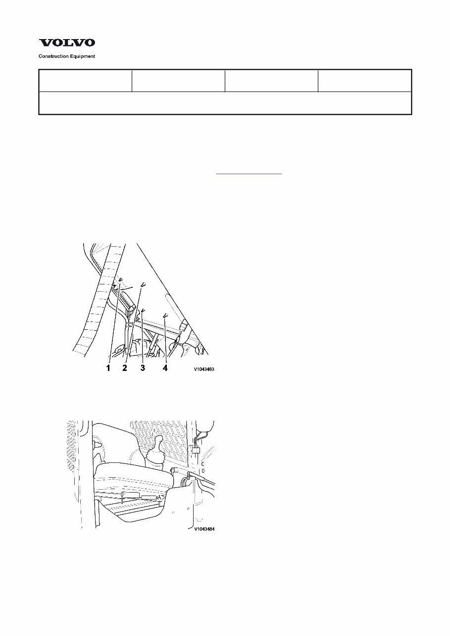
4. Remove the screws (4 pieces) under the floor.
Figure 1
V1043483
5. Tilt the cab back, remove the seat. Weight: 25 lb (11.3 kg)
Figure 2
V1043484

Service Information
Document Title: Function Group: Information Type: Date:
Operator's seat, installation 852 Service Information 2014/3/19
Profile:
SSL, MC90B [GB]
Operator's seat, installation
Op nbr
1. See section: for installation.
852 Operator's seat, removal
Service Information
Document Title: Function Group: Information Type: Date:
Seat bar, adjustment 852 Service Information 2014/3/19
Profile:
SSL, MC90B [GB]
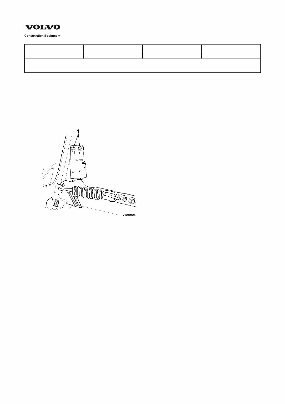
Seat bar, adjustment
Op nbr 852-095
1. Put the machine in service position.
2. Loosen both locknuts that secure the micro switch to its mounting bracket, until the micro switch can be
repositioned using a slight hand force.
Figure 1
1. Locknuts
3. Lower the seat bar to it's end position. Raise the seat bar approximately 58-76 mm (2-3") until the micro switch is
activated.
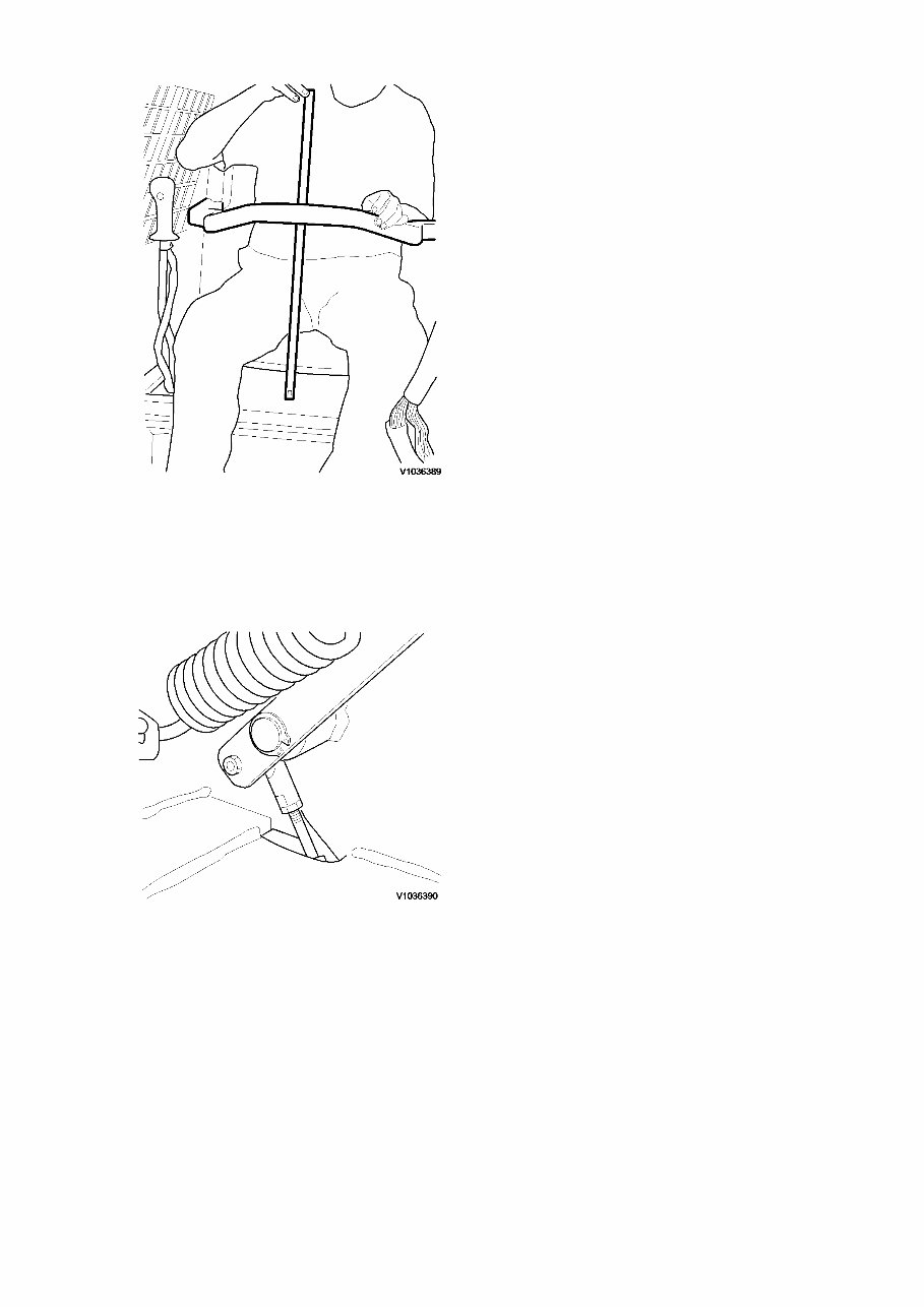
Figure 2
4. Repeat the procedure until the right position is attained, then tighten the two locknuts that secure the micro switch
to its mounting bracket securely.
5. Install the left seat bar cover and secure with a hex flange nut.
Figure 3
Service Information
Document Title: Function Group: Information Type: Date:
Safety when working with
air-conditioning refrigerant
870 Service Information 2014/3/19
Profile:
SSL, MC90B [GB]
Safety when working with air-conditioning refrigerant
Safety rules
WARNING
Wear tight-fitting goggles.
Use rubber gloves and protect other areas of exposed skin (risk of frostbite).
Avoid inhaling the refrigerant. Exposure to refrigerant can cause irritation of eyes, nose and throat. Inhaling
concentrated refrigerant can cause cardiac arrest.
Never mix R134a with air when checking for leaks. If something in the system generates a spark or the system is
pressurized, the mixture may ignite.
Use only refrigerant containers that are approved for the purpose when charging/draining refrigerant.
Never fill a refrigerant container to more than 60% of its gross weight classification. Sufficient volume must remain
in order to handle the pressure increase due to volume changes caused by temperature changes, for example, sun
exposure.
Never expose a refrigerant container to temperatures above 50 °C (122 °F). Even a correctly filled container is an
explosion hazard at temperatures above 50 °C (122 °F).
Always perform service work in well ventilated areas. R134a is heavier than air and will therefore sink and
concentrate in low areas, for example, a grease pit.
You're Reading a Preview
What's Included?
Fast Download Speeds
Offline Viewing
Access Contents & Bookmarks
Full Search Facility
Print one or all pages of your manual
$42.99
Viewed 97 Times Today


Secure transaction
What's Included?
Fast Download Speeds
Offline Viewing
Access Contents & Bookmarks
Full Search Facility
Print one or all pages of your manual
$42.99
This manual provides comprehensive maintenance and repair procedures for the Volvo MC90B Skid Steer Loader.
- It is an electronic version of the original maintenance manual, offering the advantage of zooming in anywhere on your computer for clear visibility.
- The manual covers a wide range of models and includes detailed information on general maintenance, specifications, technical features, rigging information, troubleshooting, electrical system, fuel system, power unit, lower unit, bracket unit, maintenance, index, appendix, and more.
- Written in a step-by-step format, it enables easy self-repair, potentially saving on expenses.
- Upon payment, the manual is immediately accessible.
File Format: .PDF
Compatibility: All Versions of Windows & Mac
Language: English
Requirements: Adobe Reader


