

Thomas T225, T243 HDS, T245 HDS, T245 HDK, Protough 2200 Skid Steer Loader Service Repair Workshop Manual
What's Included?
Fast Download Speeds
Online & Offline Access
Access PDF Contents & Bookmarks
Full Search Facility
Print one or all pages of your manual

REPAIR MANUAL
Publication No.46563
Date November, 2000
S / N LM000101 ONWARD
S / N LP000100 ONWARD
T225
T243 HDS
T245 HDS
T245 HDK
Protough 2200
2
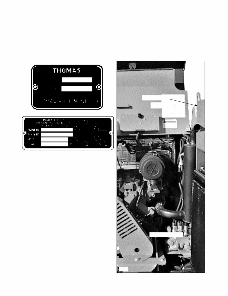
It is important when ordering replacement parts or making a service inquiry to provide both the
model number and serial number of your Thomas loader. The serial number plate is located at the
rear of the machine on the right hand side fuel tank. In the event that the serial number plate is
missing, the model number and serial number are both stamped into the mainframe inside the rear
door, next to the hydraulic control valve.
FOREWORD
S / N Stamp location
C921
S / N Tag location

3
Practically all Service work involves the need to drive
the loader. The Operators Manual, supplied with each
loader, contains safety precautions relating to driving,
operating and servicing that loader. These precautions are
as applicable to the service technicians as they are to the
operator and should be read, understood and practiced by
all personnel.
Prior to undertaking any maintenance, repair, overhaul,
dismantling or re-assembly operations, whether within the
shop facility or “out in the field”, may have an effect
upon safety, not only upon the mechanic carrying out the
work but also upon bystanders.
PERSONAL CONSIDERATIONS
* CLOTHING
The wrong clothing or carelessness in dress can
cause accidents. Check to see that you are
suitably clothed. Some jobs require special
protective equipment.
* SKIN PROTECTION
Used motor oil may cause skin cancer. Follow
work practices that minimize the amount of skin
exposed and length of time used oil stays on
your skin.
* EYE PROTECTION
The smallest eye injury may cause loss of vision.
Injury can be avoided by wearing eye protection
when engaged in chiseling, grinding, welding,
painting and any other task that involves foreign
matter.
* BREATHING PROTECTION
Fumes, dust and paint spray are unpleasant and
harmful. These can be avoided by wearing
respiratory protection.
* HEARING PROTECTION
Loud noise may damage your hearing and the
longer the exposure the greater the risks of
hearing damage. Always wear hearing protection
when working around loud machinery.
*
HAND PROTECTION
It is advisable to use a protective cream before
work to prevent irritation and skin
contamination. After work, clean your hands
with soap and water. Solvents such as white
spirits, paraffin, etc. may harm the skin.
* FOOT PROTECTION
Substantial or protective footwear with
reinforced toecaps will protect the feet from
falling objects. Additional oil-resistant
soles will help to avoid spilling.
* SPECIAL CLOTHING
For certain work it may be necessary to wear
flame or acid resistant clothing.
EQUIPMENT CONSIDERATIONS
* MACHINE GUARDS
Before using any machine, check to ensure that
the machine guards are in position and
serviceable. These guards not only prevent parts
of the body or clothing coming in contact with
the moving parts of the machine but also ward
off objects that might fly off the machine and
cause injury.
* LIFTING APPLIANCES
Always ensure that lifting equipment, such as
chains, slings, lifting brackets, hooks and eyes
are thoroughly checked before use. If in doubt,
select stronger equipment. Never stand under a
suspended load or raised implement.
* COMPRESSED AIR
The pressure from a compressed air line is often
as high as 100 PSI (6.9 Bar). any misuse may
cause injury.
Never use compressed air to blow dust, filing
dirt, etc. away from your work area unless the
correct type of nozzle is fitted.
Compressed air is not a cleaning agent. It will
only move dust etc. from one place to another.
Look around before using an air hose as
bystanders may get grit into their eyes, ears and
skin.
Avoid injury through
incorrect handling of
components. Make sure
your are capable of
lifting the object. If in
doubt, get help.
SAFETY PRECAUTIONS
CAUTION

4
* HAND TOOLS
Many cuts, abrasions and injuries are caused by
defective tools. Never use the wrong tool for the
job as this leads either to some injury or to a
poor job done.
Never Use:
- A hammer with a loose or split handle.
_ Spanners or wrenches with splayed or
worn jaws.
_ Wrenches or files as hammers; drills or
clevis pins or bolts as punches.
For removing or replacing hardened pins use a
copper or brass drift rather than a hammer.
For dismantling, overhaul and assembly of major
and sub-components always use the Special
Service Tools recommended. These will reduce
the work effort, labor time and the repair cost.
Always keep tools clean and in good working
order.
* ELECTRICITY
Electricity has become so familiar in day to day
usage that it’s potentially dangerous properties
are often overlooked. Misuse of electrical
equipment can endanger life.
Before using any electrical equipment,
particularly portable appliances, make a visual
check to ensure to make sure that the cable is not
worn or frayed and that the plugs, sockets etc.
are intact. Make sure you know where the
nearest isolating switch for your equipment is
located.
GENERAL CONSIDERATIONS
* SOLVENTS
Use only cleaning fluids and solvents that are
known to be safe. Certain types of fluids can
cause damage to components such as seals, etc.
and can cause skin irritation. Solvents should be
checked that they are suitable not only for the
cleaning of components and individual parts but
also that they do not affect the personal safety of
the user.
* HOUSEKEEPING
Many injuries result from tripping or slipping
over, or on, objects or materials left lying around
by a careless worker.
Prevent these accidents from occurring. If you
notice a hazard, don’t ignore it, remove it.
A clean hazard free place of work improves the
surroundings and daily environment for
everybody.
* FIRE
Fire has no respect for persons or property. The
destruction that a fire can cause is not always
fully realized. Everyone must be constantly on
guard.
- Extinguish matches, cigars, cigarettes etc.
before throwing them away.
- Work cleanly, disposing of waste material into
proper containers.
- Locate all the fire extinguishers and ensure all
personnel know how to operate them.
- Do not panic, warn those near and sound the
alarm.
- Do not allow or use an open flame near the
loader fuel tank, battery or component parts.
* FIRST AID
In the type of work that mechanics are engaged
in, things such as dirt, grease, fine dust etc. all
settle upon the skin and clothing. If a cut,
abrasion or burn is disregarded it may be found
that a septic condition has formed in a short time.
What appears at first to be trivial could become
painful and injurious. It only takes a few minutes
to have a fresh cut dressed but it will take longer
if you neglect it.
* CLEANLINESS
Cleanliness of the loader hydraulic system is
essential for optimum performance. When
carrying out service and repairs, plug all hose
ends and components connections to prevent dirt
entry.
Clean the exterior of all components before
carrying out any form of repair. Dirt and abrasive
dust can reduce the efficiency and working life
of a component and lead to costly replacement.
Use of a high pressure washer or steam cleaner is
recommended.
SAFETY PRECAUTIONS

5
OPERATIONAL CONSIDERATIONS
* Stop the engine, if at all possible, before
performing any service.
* Place a warning sign on loaders which, due to
service or overhaul, would be dangerous to start.
Disconnect the battery leads if leaving such a
unit unattended.
* Do not attempt to start the engine while standing
beside the loader or attempt to bypass the safety
starting system.
* Avoid prolonged running of the engine in a
closed building or in an area with inadequate
ventilation as exhaust fumes are highly toxic.
* Always turn the radiator cap to the first stop to
allow pressure in the system to dissipate when
the coolant is hot.
* Never work beneath a loader which is on soft
ground. Always take the unit to an area which
has a hard working surface, preferably concrete.
* If it is found necessary to raise the loader for
ease of maintenance, make sure that safe and
stable supports are installed beneath the main
frame before commencing work.
* Use footsteps or working platforms when
servicing those areas of the loader that are not
within easy reach.
* Before loosening any hoses or tubes, switch off
the engine, remove all pressure in the lines by
operating the foot pedals several times. This will
remove the danger of personal injury by oil
pressure.
* Prior to pressure testing, make sure all the hoses
and connectors on both the loader and on the test
machine are in good condition and tightly sealed.
Pressure readings must be taken with the gauges
specified. The correct procedure should be
rigidly observed to prevent damage to the system
or the equipment and to eliminate the possibility
of personal injury.
* Always lower equipment to the ground when
leaving the loader.
* If high lift attachments are installed on a loader,
beware of overhead power and telephone lines
when travelling. Drop attachment near to ground
level to increase stability and minimize risks.
* Do not park or attempt to service a loader on an
incline. If unavoidable, take extra care and block
the wheels.
* Escaping hydraulic / diesel fluid under pressure
can penetrate the skin causing serious injury. Do
not use your hand to check for leaks. Use a piece
of cardboard or paper to search for leaks. Stop
the engine and relieve pressure before connecting
or disconnecting lines. Tighten all connections
before starting the engine or pressurizing the
lines. If any fluid is injected into the skin, obtain
medical attention immediately.
* Prior to removing wheels and tires from a loader,
check to determine whether additional ballast
(liquid or weight) has been added. Seek
assistance and use suitable equipment to support
the weight of the wheel assembly.
* When inflating tires beware of over inflation.;
constantly check the pressure. Over inflation can
cause tires to burst and result in personal injury.
* Safety precautions are very seldom the figment
of someone’s imagination. They are the result of
sad experience where most likely someone has
paid dearly through personal injury.
* Heed these precautions and you will protect
yourself accordingly. Disregard them and you
will duplicate the sad experiences of others.
SERVICE TECHNIQUES
A. SERVICE SAFETY
Appropriate service methods and proper repair procedures
are essential for the safe, reliable operation of all motor
vehicles as well as the personal safety of the individual
doing the work. This shop manual provides general
directions for accomplishing service and repair work with
tested effective techniques. Following them will help
assure reliability.
SAFETY PRECAUTIONS

6
There are numerous variations in procedures, techniques,
tools and parts for servicing vehicles as well as in the skill
of the individual doing the work. This manual cannot
possibly anticipate all such variations and provide advice
or cautions as to each. Accordingly, anyone who departs
from the instructions provided in this manual must first
establish that he or she compromises neither his personal
safety nor the vehicle integrity by his choice of methods,
tools or parts.
B. SERVICE TECHNIQUES
Clean the exterior of all components before carrying out
any form of repair. Dirt and abrasive dust can reduce the
efficient working life of a component and lead to costly
replacement.
Use cleaning fluids which are known to be safe. Certain
types of fluid can cause damage to O rings and cause skin
irritation. Solvents should be checked that they are
suitable for the cleaning of components and also that they
do not risk the personal safety of the user.
Time spent on the preparation and cleanliness of working
surfaces will pay dividends in making the job easier and
safer and will result in overhaul components being more
reliable and efficient in operation.
Replace O rings, seals or gaskets whenever they are
disturbed. Never mix new and old seals and O rings,
regardless of condition. Always lubricate new seals and O
rings with hydraulic oil before installation.
When replacing component parts use the correct tool for
the job.
C. HOSES AND TUBES
Always replace hoses and tubes if the end connections are
damaged. Be sure any hose installed is not kinked or
twisted.
When installing a new hose, loosely connect each end and
make sure the hose takes up the designed position before
tightening the connection. Clamps should be tightened
sufficiently to hold the hose without crushing and to
prevent chafing.
The hoses are the arteries of the unit; be sure they are in
good condition when carrying out repairs or maintenance
otherwise the machines output and productivity will be
affected.
After hose replacement to a moving component, check
that the hose does not foul by moving the component
through the complete range of travel.
Hose connections which are damaged, dented , crushed or
leaking, restrict oil flow and the productivity of the
components being served. Connectors which show signs
of movement from the original swaged position have
failed and will ultimately separate completely.
A hose with a chafed outer cover will allow water entry.
Concealed corrosion of the wire reinforcement will
subsequently occur along the hose length with resultant
hose failure.
Ballooning of the hose indicates an internal leakage due
to structural failure. This condition rapidly deteriorates
and total hose failure soon occurs.
Kinked, crushed, stretched or deformed hoses generally
suffer internal structural damage which results in oil
restriction, a reduction in the speed of operation and
ultimate hose failure.
Free moving, unsupported hoses must never be allowed to
touch each other or related working surfaces. This causes
chafing which reduces hose life.
D. PRESSURE TESTING
Prior to pressure testing, be sure all hoses are in good
condition and all connections tight. Pressure readings
must be taken with gauges of specified pressure readings.
The correct procedure should be rigidly observed to
prevent damage to the system or the equipment and to
eliminate the possibility of personal injury.
E. BEARINGS
Bearings which are considered suitable for further service
should be cleaned in a suitable solvent and immersed in
clean lubricating oil until required.
Installation of a bearing can be classified into two (2)
ways:
press fit on rotating parts such as shafts and
gears, or
push fit into static locations such as reduction
gear houses.
Where possible, always install the bearing onto the
rotating components first.
SAFETY PRECAUTIONS
7
Use the correct tools or a press to install a bearing or
bushing. In the absence of the correct tools or press, heat
the bearing and / or casing in hot oil to assist the
installation of the bearing.
When bearings or bushings are removed, always carefully
check that the bearing is free from discoloration and signs
of overheating. Also check for mechanical damage such
as excessive clearance, nicks and scuffing. If in doubt,
replace the bearings or bushings.
Bearings should never be removed unless absolutely
necessary. Always use the recommended puller to reduce
the risk of bearing or related component failure.
These bearings and bushings are subjected, in normal
operation, to high working loads and adverse conditions.
Be sure during normal routine servicing, maintenance or
repair that bearings are given the right attention and are
installed with care.
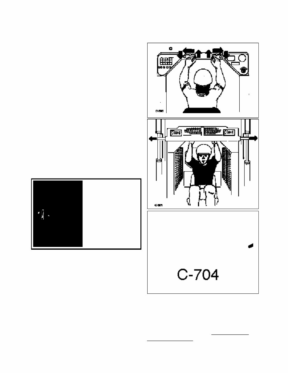
F. BOOM SUPPORTS
For safety while performing regular service or
maintenance work, the loader is equipped with boom
supports.
The boom supports, when extended, prevent the boom
arms from dropping if hydraulic pressure is relieved or
the foot control pedals are accidentally cycled.
To operate the boom supports, first remove any bucket or
attachment from the quick - tach; raise the boom arms to
full height and shut off the engine. Raise the boom
handles up and push out toward the boom arms to extend
the boom supports.
SAFETY PRECAUTIONS
To avoid personal injury,
service the loader with the
arms down and the
bucket or attachment on
the ground. If it is
necessary to service the
loader with the boom
arms raised be sure to
engage the boom
supports. Never work
under or around a loader
with raised boom arms
without boom supports
engaged.
WARNING
G. BOOM LOCKDOWNS
The boom lock down is intended to lock the loaders
boom arms in the down position for safe entry and exit of
the loader cab when using specific attachments. To
operate the boom lock down, lower the boom arms fully
down and shut off the engine. Engage the parking brake .
Install the boom lock down bars. NOTE: N/A on the
ProTough 2200 model.

8
TABLE OF CONTENTS
Section 1 Hydraulic System
Hydraulic Circuit . . . . . . . . . . . . . . . . . . . . . . . . . . . . . . . . . . . . . . .1.1
Specification & Maintenance . . . . . . . . . . . . . . . . . . . . . . . . . . . . . .1.2
General Information . . . . . . . . . . . . . . . . . . . . . . . . . . . . . . . . . . . . .1.3
Control Valve . . . . . . . . . . . . . . . . . . . . . . . . . . . . . . . . . . . . . . . . . .1.4
Hydraulic Cylinders . . . . . . . . . . . . . . . . . . . . . . . . . . . . . . . . . . . . .1.5
Oil Filter . . . . . . . . . . . . . . . . . . . . . . . . . . . . . . . . . . . . . . . . . . . . . .1.6
Oil Cooler . . . . . . . . . . . . . . . . . . . . . . . . . . . . . . . . . . . . . . . . . . . . .1.7
Oil Reservoir . . . . . . . . . . . . . . . . . . . . . . . . . . . . . . . . . . . . . . . . . . .1.8
Trouble Shooting . . . . . . . . . . . . . . . . . . . . . . . . . . . . . . . . . . . . . . .1.9
Torque Chart . . . . . . . . . . . . . . . . . . . . . . . . . . . . . . . . . . . . . . . . . . .1.10
Conversion Chart . . . . . . . . . . . . . . . . . . . . . . . . . . . . . . . . . . . . . . .1.11
Section 2 Hydrostatic Drive System
Hydrostatic Drive Circuit ..................................................................2.1
Specifications.....................................................................................2.2
General Information ...........................................................................2.3
Trouble Shooting ...............................................................................2.4
Pressure Tests .....................................................................................2.5
Towing Procedure ..............................................................................2.6
Flushing The Hydraulic System ........................................................2.7
Start - up Procedure ...........................................................................2.8
Gear Pump Replacement ...................................................................2.9
Tandem Pump Replacement ..............................................................2.10
Drive Motor .......................................................................................2.11
Torque Chart ......................................................................................2.12
Conversion Chart ...............................................................................2.13
Section 3 Final Drive
Specifications.....................................................................................3.1
Maintenance .......................................................................................3.2
Drive Chain........................................................................................3.3
Idler Sprocket & Shaft .......................................................................3.4
Axle Assembly ...................................................................................3.5
Trouble Shooting ...............................................................................3.6
Section 4 Controls
Trouble Shooting ...............................................................................4.1
Steering ..............................................................................................4.2
Steering Locks ...................................................................................4.3
Restraint Bar ......................................................................................4.4
Parking Brake ....................................................................................4.5
Foot Pedals .........................................................................................4.6
Hand Controls ....................................................................................4.7
Throttle ...............................................................................................4.8
Auxiliary Control ...............................................................................4.9
Hi - Flow Controls .............................................................................4.10

9
TABLE OF CONTENTS
Section 5 Electrical
Specifications . . . . . . . . . . . . . . . . . . . . . . . . . . . . . . . . . . . . . . . . . .5.1
Wiring Schematics . . . . . . . . . . . . . . . . . . . . . . . . . . . . . . . . . . . . . .5.2
Instrumentation . . . . . . . . . . . . . . . . . . . . . . . . . . . . . . . . . . . . . . . . .5.3
Ignition Switch . . . . . . . . . . . . . . . . . . . . . . . . . . . . . . . . . . . . . . . . .5.4
Manifold Pre - Heater . . . . . . . . . . . . . . . . . . . . . . . . . . . . . . . . . . . .5.5
Battery . . . . . . . . . . . . . . . . . . . . . . . . . . . . . . . . . . . . . . . . . . . . . . . .5.6
Electrical Panel . . . . . . . . . . . . . . . . . . . . . . . . . . . . . . . . . . . . . . . . .5.7
Starter Circuit . . . . . . . . . . . . . . . . . . . . . . . . . . . . . . . . . . . . . . . . . .5.8
Charging Circuit . . . . . . . . . . . . . . . . . . . . . . . . . . . . . . . . . . . . . . . .5.9
Safety Circuit . . . . . . . . . . . . . . . . . . . . . . . . . . . . . . . . . . . . . . . . . .5.10
Auxiliary Circuit . . . . . . . . . . . . . . . . . . . . . . . . . . . . . . . . . . . . . . . .5.11
Accessory Circuit . . . . . . . . . . . . . . . . . . . . . . . . . . . . . . . . . . . . . . .5.12
Trouble Shooting . . . . . . . . . . . . . . . . . . . . . . . . . . . . . . . . . . . . . . .5.13
Section 6 Main Frame
Quick - Tach .......................................................................................6.1
Boom Arms ........................................................................................6.2
Boom Support ....................................................................................6.3
ROPS .................................................................................................6.4
Rear Door...........................................................................................6.5
Section 7 Engine
Specifications.....................................................................................7.1
Trouble Shooting ...............................................................................7.2
Distribution / Service Centers............................................................7.3
Filters .................................................................................................7.4
Engine Cooler ....................................................................................7.5
Alternator and Belt ............................................................................7.6
Sending Units .....................................................................................7.7
Manifold Heater.................................................................................7.7
Stop Solenoid .....................................................................................7.8
Starter .................................................................................................7.8
Thermostat .........................................................................................7.9
U - Joint .............................................................................................7.10
Removal / Replacement .....................................................................7.11
Section 8 Maintenance & Specifications
Preventative Maintenance Schedule ..................................................8.1
50 Hour Service Schedule .................................................................8.2
Specifications.....................................................................................8.3
Torque Specifications ........................................................................8.4
Sound Power Level Specifications ....................................................8.5
Decals .................................................................................................8.6
Special Tools ......................................................................................8.7

10
NOTES
You're Reading a Preview
What's Included?
Fast Download Speeds
Online & Offline Access
Access PDF Contents & Bookmarks
Full Search Facility
Print one or all pages of your manual
$35.99
Viewed 27 Times Today


Secure transaction
What's Included?
Fast Download Speeds
Online & Offline Access
Access PDF Contents & Bookmarks
Full Search Facility
Print one or all pages of your manual
$35.99
This is a comprehensive service repair workshop manual for the Thomas T225, T243 HDS, T245 HDS, T245 HDK, Protough 2200 Skid Steer Loader. The manual contains easy-to-read text sections with high-quality diagrams and instructions, making it useful for both DIY enthusiasts and experienced mechanics. It provides step-by-step instructions and detailed exploded pictures and diagrams to assist in completing the required job correctly and efficiently.
- Section 1: Hydraulic System
- Section 2: Hydrostatic Drive System
- Section 3: Final Drive
- Section 4: Controls
- Section 5: Electrical
- Section 6: Main Frame
- Section 7: Engine
- Section 8: Maintenance & Specifications
- And More......
File Format: PDF
Compatible: All Versions of Windows & Mac
Language: English
Requirements: Adobe Reader & Win
All pages are printable, allowing you to save on postage and packaging costs. It is a valuable resource to keep your vehicle working properly.


