Contents INTRODUCTION DISTRIBUTION SYSTEMS A POWER PRODUCTION B POWER TRAIN C TRAVELLING D BODY AND STRUCTURE E WORKING ARM H TOOLS AND COUPLERS J 6-80050 1 17/06/2005
INTRODUCTION Basic instructions ( - A.90.A.05) LS185.B, LS190.B, LT185.B, LT190.B, LS180.B Technical Information This manual has been produced by a new technical information system. This new system is designed to deliver technical information electronically through CDROM and in paper manuals. A coding system called ICE has been developed to link the technical information to other Product Support functions e.g. Warranty. Technical information is written to support the maintenance and service of the functions or systems on a customers machine. When a customer has a concern on his machine it is usually because a function or system on his machine is not working at all, is not working efficiently, or is not responding correctly to his commands. When you refer to the technical information in this manual to resolve that customers concern, you will find all the information classified using the new ICE coding, according to the functions or systems on that machine. Once you have located the technical information for that function or system then you will find all the mechanical, electrical or hydraulic devices, components, assemblies and sub-assemblies for that function or system. You will also find all the types of information that have been written for that function or system, the technical data (specifications), the functional data (how it works), the diagnostic data (fault codes and troubleshooting) and the service data (remove, install adjust, etc.). By integrating this new ICE coding into technical information , you will be able to search and retrieve just the right piece of technical information you need to resolve that customers concern on his machine. This is made possible by attaching 3 categories to each piece of technical information during the authoring process. The first category is the Location, the second category is the Information Type and the third category is the Product: • LOCATION - is the component or function on the machine, that the piece of technical information is going to describe e.g. Fuel tank. • INFORMATION TYPE - is the piece of technical information that has been written for a particular component or function on the machine e.g. Capacity would be a type of Technical Data that would describe the amount of fuel held by the Fuel tank. • PRODUCT - is the model that the piece of technical information is written for. Every piece of technical information will have those 3 categories attached to it. You will be able to use any combination of those categories to find the right piece of technical information you need to resolve that customers concern on his machine. That information could be: • the description of how to remove the cylinder head • a table of specifications for a hydraulic pump • a fault code • a troubleshooting table • a special tool How to Use this Manual This manual is divided into Sections. Each Section is then divided into Chapters. Contents pages are included at the beginning of the manual, then inside every Section and inside every Chapter. An alphabetical Index is included at the end of a Chapter. Page number references are included for every piece of technical information listed in the Chapter Contents or Chapter Index. Each Chapter is divided into four Information types: • (D) Technical Data (specifications) for all the mechanical, electrical or hydraulic devices, components and, assemblies. • (C) Functional Data (how it works) for all the mechanical, electrical or hydraulic devices, components and assemblies. • (G) Diagnostic Data (fault codes, electrical and hydraulic troubleshooting) for all the mechanical, electrical or hydraulic devices, components and assemblies. 6-80050 1 17/06/2005 3
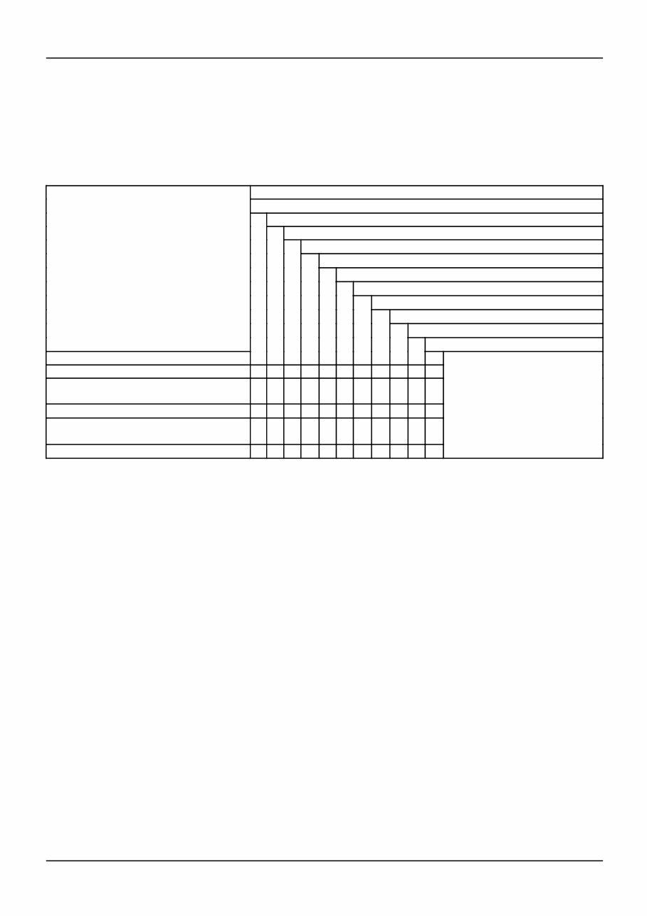
INTRODUCTION • (F) Service data (remove disassembly, assemble, install) for all the mechanical, electrical or hydraulic devices, components and assemblies. Sections Sections are grouped according to the main functions or a systems on the machine. Each Section is identified by a letter A, B, C etc. The amount of Sections included in the manual will depend on the type and function of the machine that the manual is written for. Each Section has a Contents page listed in alphabetic/numeric order. This table illustrates which Sections could be included in a manual for a particular product. SECTION A - Distribution Systems B - Power Production C - Power Train D - Travelling E - Body and Structure F - Frame Positioning G - Tool Positioning H - Working Arm J - Tools and Couplers K - Crop Processing L - Field Processing PRODUCT Tractors X X X X X X X X Vehicles with working arms: backhoes, excavators, skid steers, ..... X X X X X X X X X Combines, forage harvesters, balers, .... X X X X X X X X X X Seeding, planting, floating, spraying equipment, .... X X X X X X X X X Mounted equipment and tools, ..... X X X X Chapters Each Chapter is identified by a letter and number combination e.g. Engine B.10.A The first letter is identical to the Section letter i.e. Chapter B.10 is inside Section B, Power Production. CONTENTS The Chapter Contents lists all the (D) technical data (specifications), (C) functional data (how it works), (F) service data (remove, install adjust, etc..) and (G) diagnostic data (fault codes and troubleshooting) that have been written in that Chapter for that function or system on the machine. Contents POWER PRODUCTION ENGINE _ 10.A TECHNICAL DATA ENGINE - General specification (B.10.A - D.40.A.10) 3 FUNCTIONAL DATA ENGINE - Dynamic description (B.10.A - C.30.A.10) 4 SERVICE ENGINE - Remove (B.10.A - F.10.A.10) 5 DIAGNOSTIC ENGINE - Troubleshooting (B.10.A - G.40.A.10) 6 INDEX The Chapter Index lists in alphabetical order all the types of information (called Information Units) that have been written in that Chapter for that function or system on the machine. 6-80050 1 17/06/2005 4
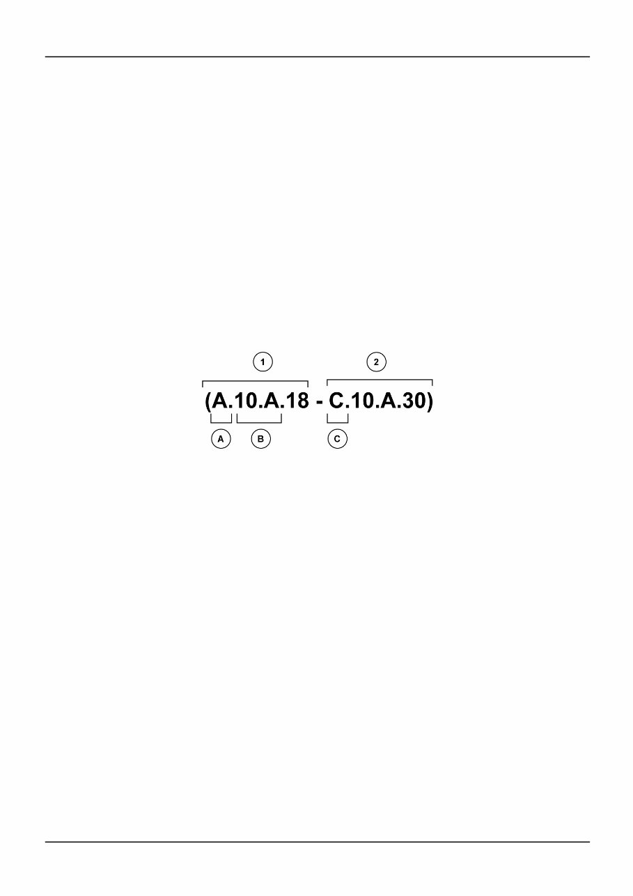
INTRODUCTION Index POWER PRODUCTION - B ENGINE ENGINE - Dynamic description (B.10.A - C.30.A.10) 4 ENGINE - General specification (B.10.A - D.40.A.10) 3 ENGINE - Remove (B.10.A - F.10.A.10) 5 ENGINE - Troubleshooting (B.10.A - G.40.A.10) 6 Information Units and Information Search Each chapter is composed of information units. Each information unit has the ICE code shown in parentheses which indicates the function and the type of information written in that information unit. Each information unit has a page reference within that Chapter. The information units provide a quick and easy way to find just the right piece of technical information you are looking for. example information unit Stack valve - Sectional View (A.10.A.18 - C.10.A.30) Information Unit ICE code A 10.A 18 C 10.A.30 ICE code classification Distribution systems Primary hydraulic power Stack valve Functional data Sectional view CRIL03J033E01 1 Navigate to the correct information unit you are searching for by identifying the function and information type from the ICE code. • (1) Function and (2) Information type. • (A) corresponds to the sections of the repair manual. (B) corresponds to the chapters of the repair manual. (C) corresponds to the type of information listed in the chapter contents, (D) Technical data, (C) Functional Data, (G) Diagnostic or (F) Service. (A) and (B) are also shown in the page numbering on the page footer. THE REST OF THE CODING IS NOT LISTED IN ALPHA-NUMERIC ORDER IN THIS MANUAL. • You will find a table of contents at the beginning and end of each section and chapter. You will find an alphabetical index at the end of each chapter. • By referring to (A), (B) and (C) of the coding, you can follow the contents or index (page numbers) and quickly find the information you are looking for. 6-80050 1 17/06/2005 5
INTRODUCTION Page Header and Footer The page header will contain the following references: • Section and Chapter description The page footer will contain the following references: • Publication number for that Manual, Section or Chapter. • Version reference for that publication. • Publication date • Section, chapter and page reference e.g. A.10.A / 9 6-80050 1 17/06/2005 6
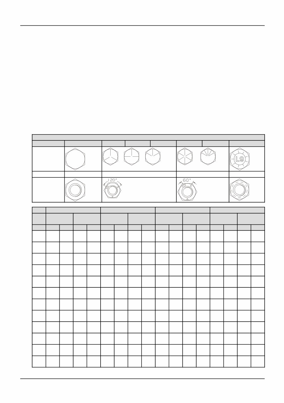
INTRODUCTION Torque ( - A.90.A.10) LS185.B, LS190.B, LT185.B, LT190.B, LS180.B BOLT TORQUE INFORMATION DECIMAL HARDWARE 1. Fasteners should be replaced with the same or higher grade. If higher grade fasteners are used, these should only be tightened to the strength of the original. 2. Make sure the fasteners threads are clean and that thread engagement is started. This will prevent them from failing when being tightened. 3. Tighten plastic insert or crimped steel-type lock nuts to approximately 50 % of the dry torque, applied to the nut, not to the bolt head. Tighten toothed or serrated-type lock nuts to the full torque value. 4. The L9 (Alloy) fasteners torque values are for a bolt, nut, and two washers. When using L9 (Alloy) fasteners, do not use the values in this table for tapped holes. GRADE 1 or 2 5 5.1 5.2 8 8.2 L9 (Alloy) SAE Markings for Bolts and Cap Screws 2 5 8 L9 (Alloy) SAE Markings for Hex Nuts GRADE 2 * GRADE 5, 5.1 or 5.2 GRADE 8 or 8.2 GRADE L9 (Alloy) Dry ** Lubricated ** Dry** Lubricated ** Dry** Lubricated ** Head Nut SIZE Nm lb/ft Nm lb/ft Nm lb/ft Nm lb/ft Nm lb/ft Nm lb/ft Nm lb/ft Nm lb/ft 1/4 UNF 7.5 5.5 5.7 4.2 10.8 8 8.5 6.3 16.3 12 12.2 9 13.6 10 14.9 11 1/4 UNC 8.5 6.3 6.4 4.7 13.6 10 9.8 7.2 19 14 13.6 10 16.3 12 17.6 13 5/16 UNF 15 11 11 8 23 17 18 13 33 24 24 18 26 19 28 21 5/16 UNC 16 12 12 9 26 19 19 14 37 27 27 20 27 20 31 23 3/8 UNF 27 20 20 15 41 30 31 23 61 45 47 35 41 30 45 33 3/8 UNC 31 23 23 17 47 35 34 25 68 50 47 35 47 35 52 38 7/16 UNF 43 32 33 24 68 50 47 35 95 70 68 50 75 55 81 60 7/16 UNC 49 36 37 27 75 55 54 40 108 80 81 60 81 60 88 65 1/2 UNF 68 50 47 35 102 75 75 55 149 110 108 80 115 85 129 95 1/2 UNC 75 55 54 40 115 85 88 65 163 120 122 90 129 95 142 105 9/16 UNF 95 70 75 55 149 110 108 80 203 150 149 110 163 120 190 140 9/16 UNC 108 80 81 60 163 120 122 90 231 170 176 130 183 135 203 150 6-80050 1 17/06/2005 7
INTRODUCTION GRADE 2 * GRADE 5, 5.1 or 5.2 GRADE 8 or 8.2 GRADE L9 (Alloy) Dry ** Lubricated ** Dry** Lubricated ** Dry** Lubricated ** Head Nut SIZE Nm lb/ft Nm lb/ft Nm lb/ft Nm lb/ft Nm lb/ft Nm lb/ft Nm lb/ft Nm lb/ft 5/8 UNF 136 100 102 75 203 150 149 110 285 210 217 160 231 170 251 185 5/8 UNC 149 110 115 85 231 170 176 130 325 240 244 180 258 190 278 205 3/4 UNF 237 175 176 130 353 260 271 200 515 380 380 280 359 265 393 290 3/4 UNC 271 200 190 140 407 300 298 220 570 420 420 310 447 330 481 355 7/8 UNF 231 170 170 125 583 430 434 320 814 600 610 450 644 475 685 505 7/8 UNC 244 180 190 140 637 470 475 350 909 670 678 500 705 520 793 585 1 UNF 339 250 258 190 868 640 651 480 1234 910 922 680 746 550 1051 775 1 UNC 380 280 285 210 976 720 732 540 1383 1020 1031 760 949 700 1220 900 1-1/8 UNF 475 350 366 270 1071 790 800 590 1749 1290 1315 970 1390 1025 1559 1150 1-1/8 UNC 542 400 407 300 1207 890 909 670 1953 1440 1464 1080 1559 1150 1797 1325 1-1/4 UNF 678 500 515 380 1519 1120 1139 840 2468 1820 1844 1360 1898 1400 2170 1600 1-1/4 UNC 746 550 570 420 1681 1240 1261 930 2726 2010 2048 1510 2170 1600 2373 1750 1-1/2 UNF 1180 870 881 650 2644 1950 1980 1460 4285 3160 3214 2370 3932 2900 4407 3250 1-1/2 UNC 1329 980 990 730 2983 2200 2224 1640 4827 3560 3621 2670 4475 3300 4949 3650 IMPORTANT: DO NOT use these values if a different torque value or tightening procedure is given for a specific application. Torque values listed are for general use only. Check tightness of fasteners periodically. Shear bolts are designed to fail under predetermined loads. Always replace shear bolts with identical grade. NOTES • * - Grade 2 applies for hex caps (not hex bolts) up to 152 mm (6 in) long. Grade 1 applies for hex cap screws over 152 mm (6 in) long, and for all other types of bolts and screws of any length. • ** - "Lubricated" means coated with a lubricant such as engine oil, or fasters with phosphate and oil coatings. "Dry" means plaind or zinc plated without any lubriation. TORQUE SPECIFICATIONS - METRIC HARDWARE GRADE 8.8 Bolts, Nuts and Studs GRADE 10.9 Bolts, Nuts and Studs Dry Dry SIZE Nm lb/in lb/ft Nm lb/in lb/ft M4 3 to 4 31 to 35 5 to 6 44 to 49 M5 5 to 6 49 to 55 8 to 9 71 to 79 M6 10 to 11 84 to 94 14 to 15 120 to 136 M8 23 to 26 229 to 277 33 to 37 293 to 329 M10 46 to 51 408 to 460 65 to 74 48 to 54 M12 80 to 90 59 to 66 114 to 128 85 to 94 M14 128 to 145 94 to 106 183 to 205 136 to 153 M16 200 to 220 149 to 161 285 to 320 208 to 235 6-80050 1 17/06/2005 8
New Holland LS180 - LS/LT185 - LS/LS190 Skid Steer Loader Service & Repair Manual
Models covered:
LS180.B
LS185.B
LS190.B
LT185.B
LT190.B
Engines covered:
334/M2
334T/M2
445/M2
This technical manual contains service, maintenance, troubleshooting, and replacement procedures for your loader, including step-by-step instructions, clear images, and exploded-view illustrations.
It provides manufacturer-sourced procedures, combined with illustrations, making it possible for anyone to safely and efficiently service and repair their loader.
Comprehensive diagrams, detailed illustrations, and all the manufacturer's specifications and technical information you might need are included.
Useful for both professional mechanics and DIY enthusiasts, this manual is easily accessible on various electronic devices, including PC & Mac computers, Android and Apple smartphones & tablets, etc. It requires Adobe Reader (free) for viewing.
Recently Viewed
5,521,897Happy Clients
2,594,462eManuals
1,120,453Trusted Sellers
15Years in Business
Price:
Actual Price:
New Holland LS180 - LS/LT185 - LS/LS190 Skid Steer Loader OEM Service & Repair Manual