,Q M444 M500 M600 M610 • Bobcal® SERVICE MANUAL (/jj) Bobcat Printed In U.S.A. eBobcat~2001
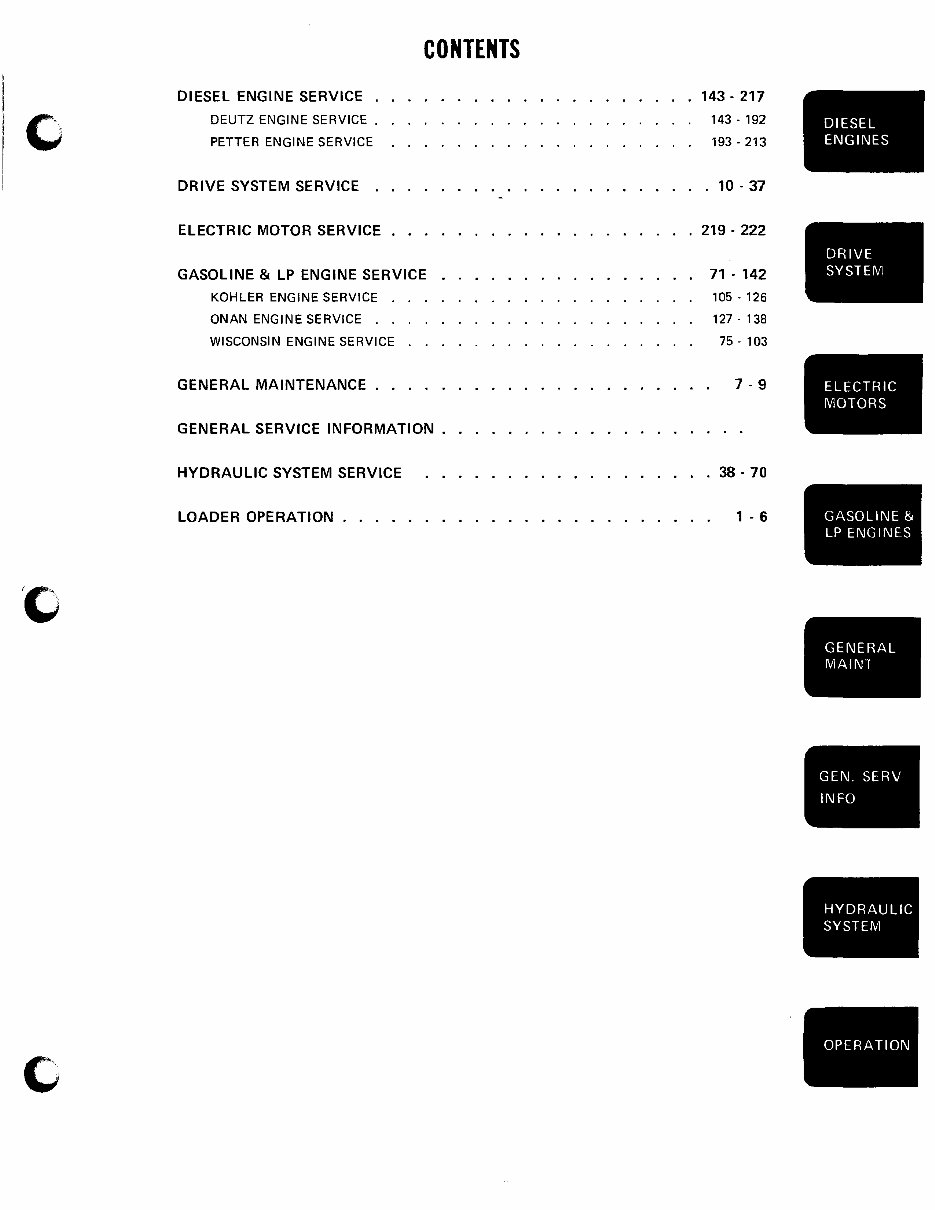
/(1 c DIESEL ENGINE SERVICE . DEUTZ ENGINE SERVICE. PETTER ENGINE SERVICE DRIVE SYSTEM SERVICE . ELECTRIC MOTOR SERVICE CONTENTS GASOLINE & LP ENGINE SERVICE KOHLER ENGINE SERVICE . ONAN ENGINE SERVICE . . WISCONSIN ENGINE SERVICE GENERAL MAINTENANCE . . GENERAL SERVICE INFORMATION. HYDRAULIC SYSTEM SERVICE LOADER OPERATION ..... 143 - 217 143 - 192 193 - 213 . 10 - 37 219 - 222 71 - 142 105·126 127·138 75· 103 7-9 38 - 70 1 - 6 DIESEL ENGINES DRIVE SYSTEM ELECTRIC MOTORS GASOLINE & LP ENGINES GENERAL MAINT GEN. SERV INFO HYDRAULIC SYSTEM OPERATION
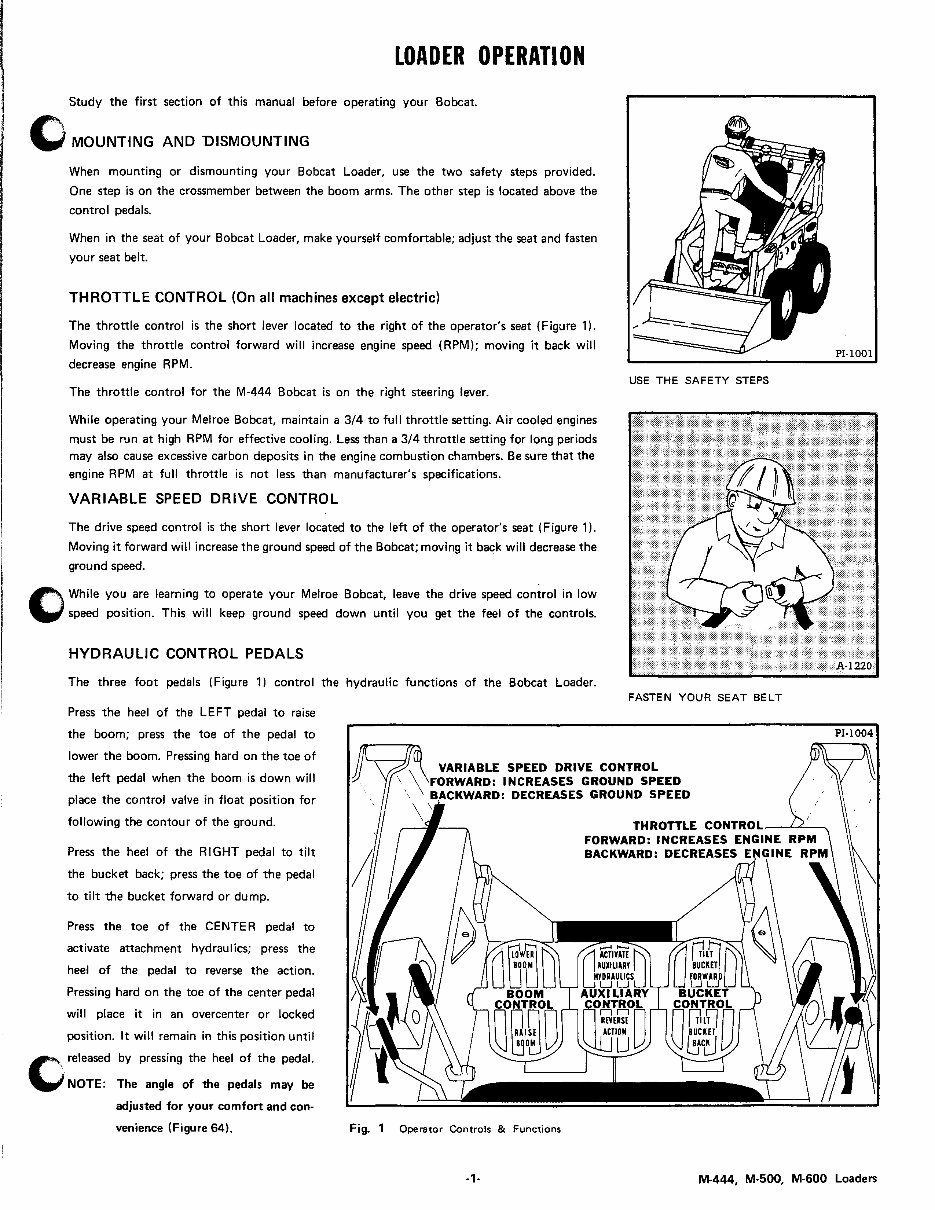
LOADER OPERATION Study the first section of this manual before operating your Bobcat. C MOUNTING AND DISMOUNTING When mounting or dismounting your Bobcat Loader, use the two safety steps provided. One step is on the crossmember between the boom arms. The other step is located above the control pedals. When in the seat of your Bobcat Loader, make yourself comfortable; adjust the seat and fasten your seat belt. THROTTLE CONTROL {On all machines except electric} The throttle control is the short lever located to the right of the operator's seat (Figure 1). Moving the throttle control forward will increase engine speed (RPM); moving it back will decrease engine RPM. The throttle control for the M-444 Bobcat is on the right steering lever. While operating your Melroe Bobcat, maintain a 3/4 to full throttle setting. Air cooled engines must be run at high RPM for effective cooling. Less than a 3/4 throttle setting for long periods may also cause excessive carbon deposits in the engine combustion chambers. Be sure that the engine RPM at full throttle is not less than manufacturer's specifications. VARIABLE SPEED DRIVE CONTROL The drive speed control is the short lever located to the left of the operator's seat (Figure 1). Moving it forward will increase the ground speed of the Bobcat; moving it back will decrease the ground speed. 1"\ While you are learning to operate your Melroe Bobcat, leave the drive speed control in low ..., speed position. This will keep ground speed down until you get the feel of the controls. HYDRAULIC CONTROL PEDALS The three foot pedals (Figure 1) control the hydraulic functions of the Bobcat Loader. USE THE SAFETY STEPS FASTEN YOUR SEAT BELT Press the heel of the LEFT pedal to raise the boom; press the toe of the pedal to lower the boom. Pressing hard on the toe of the left pedal when the boom is down will place the control valve in float position for following the contour of the ground. VARIABLE SPEED DRIVE CONTROL Press the heel of the RIGHT pedal to tilt the bucket back; press the toe of the pedal to tilt the bucket forward or dump. Press the toe of the CENTER pedal to activate attachment hydraulics; press the heel of the pedal to reverse the action. Pressing hard on the toe of the center pedal will place it in an overcenter or locked position. It will remain in this position until I'A\ released by pressing the heel of the pedal. ~ NOTE: The angle of the pedals may be adjusted for your comfort and con- venience (Figure 64). INCREASES GROUND SPEED DECREASES GROUND SPEED Fig. 1 Operator Controls & Functions THROTTLE CONTROL_--''''"''-----. FORWARD: INCREASES BACKWARD: DEICRI~A~;ES PI· IDOl -1- M-444, M-500, M-600 Loaders
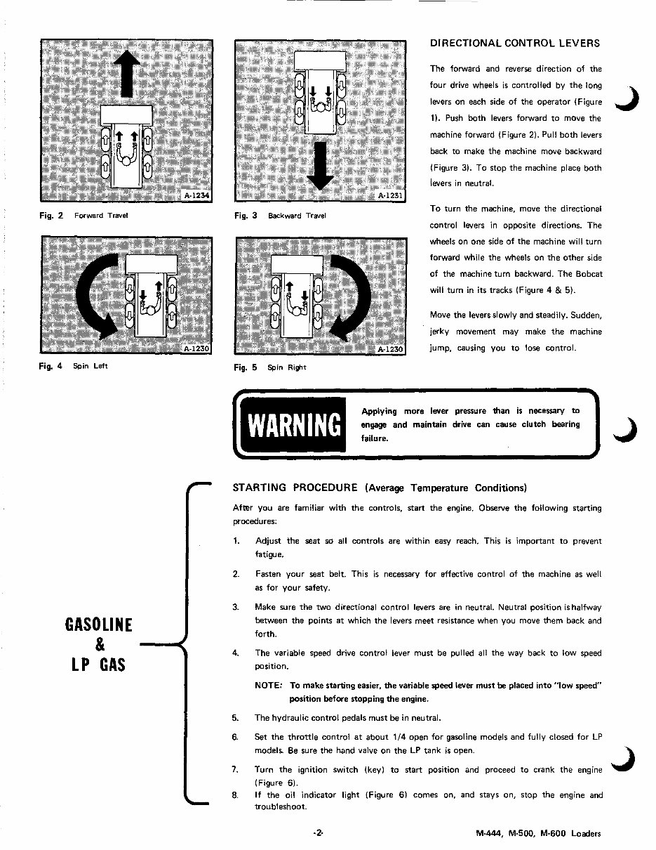
Fig. 2 Forward Travel Fig. 4 Spin Left GASOLINE & LP GAS DIRECTIONAL CONTROL LEVERS The forward and reverse direction of the four drive wheels is controlled by the long levers on each side of the operator (Figure 1). Push both levers forward to move the machine forward (Figure 2). Pull both levers back to make the machine move backward (Figure 3). To stop the machine place both levers in neutral. Fig. 3 Backward Travel To turn the machine, move the directional control levers in opposite directions. The wheels on one side of the machine will turn forward while the wheels on the other side of the machine turn backward. The Bobcat will turn in its tracks (Figure 4 & 5). Move the levers slowly and steadily. Sudden, jerky movement may make the machine jump, causing you to lose control. Fig. 5 Spin Ri~t WARNING Applying more lever pressure than is necessary to engage and maintain drive can cause clutch bearing failure. STARTING PROCEDURE (Average Temperature Conditions) After you are familiar with the controls, start the engine. Observe the following starting procedures: 1. Adjust the seat so all controls are within easy reach. This is important to prevent fatigue. 2. Fasten your seat belt. This is necessary for effective control of the machine as well as for you r safety. 3. 4. Make sure the two directional control levers are in neutral. Neutral position is halfway between the points at which the levers meet resistance when you move them back and forth. The variable speed drive control lever must be pulled all the way back to low speed position. NOTE: To make starting easier, the variable speed lever must be placed into "low speed" position before stopping the engine. 5. The hydraulic control pedals must be in neutral. 6. Set the throttle control at about 1/4 open for gasoline models and fully closed for LP models. Be sure the hand valve on the LP tank is open. 7. Turn the ignition switch (key) to start position and proceed to crank the engine (Figure 6). 8. If the oil indicator light (Figure 6) comes on, and stays on, stop the engine and trou bl eshoot. ·2· M·444, M·500, M·600 Loaders
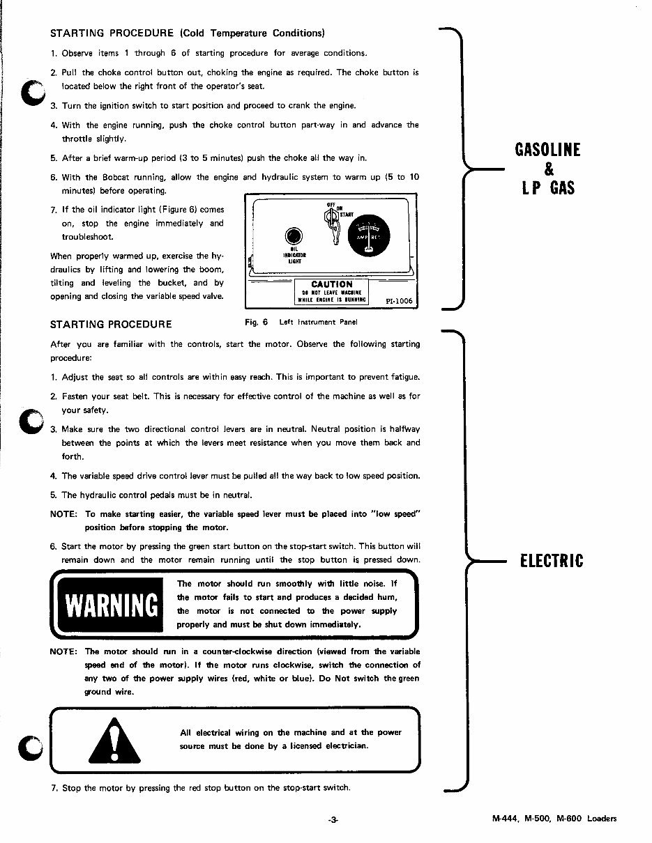
C STARTING PROCEDURE (Cold Temperature Conditions) 1. Observe items 1 through 6 of starting procedure for average conditions. 2. Pull the choke control button out, choking the engine as required. The choke button is located below the right front of the operator's seat. 3. Turn the ignition switch to start position and proceed to crank the engine. 4. With the engine running, push the choke control button part·way in and advance the throttl e 51 ightl y. 5. After a brief warm-up period (3 to 5 minutes) push the choke all the way in. 6. With the Bobcat running, allow the engine and hydraulic system to warm up (5 to 10 minutes) before operating. 7. If the oil indicator light (Figure 6) comes on, stop the engine immediately and troubleshoot. When properly warmed up, exercise the hy· draulics by lifting and lowering the boom, tilting and leveling the bucket, and by opening and closing the variable speed valve. I~ - ~ .• OIL INDICATOR UGHT ·1 CAUTION J DO NOT LEAVE IACHIME WHILE ENCINE IS IDUINC PI-l 006 STARTING PROCEDURE Fig. 6 Left Instrument Panel After you are familiar with the controls, start the motor. Observe the following starting procedure: 1. Adjust the seat so all controls are within easy reach. This is important to prevent fatigue. 2. Fasten your seat belt. This is necessary for effective control of the machine as well as for your safety. Make sure the two directional control levers are in neutral. Neutral position is halfWay between the points at which the levers meet resistance when you move them back and forth. 4. The variable speed drive control lever must be pulled all the way back to low speed position. 5. The hydraulic control pedals must be in neutral. NOTE: To make starting easier, the variable speed lever must be placed into "low speed" position before stopping the motor. 6. Start the motor by pressing the green start button on the stop-start switch. This button will remain down and the motor remain running until the stop button is pressed down. WARNING The motor should run smoothly with little noise. If the motor fails to start and produces a decided hum, the motor is not connected to the power supply properly and must be shut down immediately. NOTE: The motor should run in a counter-clockwise direction (viewed from the variable speed end of the motor). If the motor runs clockwise, switch the connection of any two of the power supply wires (red, white or blue). Do Not switch the green ground wire. All electrical wiring on the machine and at the power source must be done by a licensed electrician. 7. Stop the motor by pressing the red stop button on the stop-start switch. -3- GASOLINE & LP GAS ELECTRIC M-444, M-500, M-600 Loaders
DEUTZ DIESEL STARTING PROCEDURE (Average Temperature Conditions) After you are familiar with the controls, start the engine. Observe the fDllowing starting procedure: 1. 2. Adjust the seat so all controls are within easy reach. This is important to prevent fatigue. Fasten your seat belt. This is necessary for effective control of the machine as well as for your sefety. 3. Make sure the two directional control levers are in neutral. The neutral position is half- way between the points at which the levers meet resistance when you move them back and forth_ 4_ The variable speed drive control lever must be pulled all the way back to low speed position. 5. All three hydraulic control pedals must be in neutral. NOTE: To make starting easier, the variable speed lever must be placed into "low speed" position before stopping the engine_ 6. Set the throttle control at about 1/2 open_ Turn on the electric power switch (key) on the left instrument panel (Figure 7). 7. The engine pre-heater button is located on the left instrument panel. Press and hold it until the indicator light (located on the main frame to the left rear of the operator's seat) glows brightly. This usually takes 30 to 60 seconds. If the indicator light fails to glow, refer to the troubleshooting section of this manual. NOTE: If the engine is warm there is no need to preheat. a Turn the electric power switch (key) to start position and proceed to crank the engine. As soon as the engine starts to fire, release the key. The starting motor should not be kept running for more than 20 seconds at a time. Waiting about a minute before each starting attempt will help prolong the life of the battery_ 9. If the oil indicator light (Figure 7) comes on, stop the engine and troubleshoot. 10. To stop the engine, turn off the electric power switch and pull the throttle control all the way back. Hold it there until the engine stops. WARNING Do not stop the engine suddenly when running under full load. Let it idle for several minutes before stopping. ALWAYS LOWER THE BOOM and STOP THE EN- GINE before dismounting. STARTING PROCEDURE (Cold Temperature Conditions) 1. Observe items 1 through 5 of starting procedure for average temperature conditions. 2. Press the starting fuel allowance button once. It is located at the right side of the engine, on the injector pump. 3. 4. Set the throttle control at about 1/4 open. Press and hold the preheater button until the indicator light glows brightly_ This should take about 1 to 2 minutes. The indicator light is located on the main frame to the left rear of the operator's seat. .4- M-444, M-500, M-600 Loaders
This workshop service repair manual is a valuable resource for both professional mechanics and DIY enthusiasts. It covers a range of engine types including 4-cylinder air-cooled gasoline or LP gas engines and 2-cylinder air-cooled gasoline or LP gas and diesel engines.
The manual includes detailed sections on preventive maintenance, hydraulic systems, drive systems, electrical systems, engine systems, troubleshooting, and specifications. It also provides comprehensive coverage of safety instructions, torque specifications, delivery report, loader identification, and more.
Featuring detailed exploded views, step-by-step procedures with illustrations, and printable pages, this comprehensive manual is an essential tool for repairing, maintaining, and servicing the BOBCAT M444, M500, M600, and M610 skid steer loaders.