SERVICE MANUAL SM61005 255 / 265 TANDEM ROLLER December 2000
CALIFORNIA Proposition 65 Warning Diesel engine exhaust and some of its constituents are known to the State of California to cause cancer, birth defects, and other reproductive harm.
table of contents iii HYDRAULIC SCHEMATIC ............................................................................ 4 - 31 HYDRAULIC SCHEMATIC (“K” model) ......................................................... 4 - 32 “K” MODEL SYSTEMS .................................................................................. 4 - 33 HYDRAULIC COMPONENTS POCLAIN MC05 PROPULSION MOTOR ...................................................... 4 - 38 SAUER/SUNDSTRAND SERIES 42 PROPULSION PUMP.......................... 4 - 41 SECTION FIVE POWER TRAIN DRUM REMOVAL .......................................................................................... 5 - 11 DRIVE MOTOR REMOVAL ........................................................................... 5 - 11 DRIVE MOTOR REPAIR ............................................................................... 5 - 13 DRIVE MOTOR INSTALLATION ................................................................... 5 - 13 DRUM DRIVE BEARING REMOVAL ............................................................. 5 - 13 DRUM BEARING INSTALLATION................................................................. 5 - 15 DRUM INSTALLATION.................................................................................. 5 - 15 PNEUMATIC TIRE DRIVE ............................................................................. 5 - 16 SECTION SIX PARKING BRAKE SYSTEM PARK BRAKE TESTING.................................................................................. 6 - 5 BRAKE RELEASE FOR TOWING ................................................................... 6 - 5 TOWING PROCEDURE ............................................................................. 6 - 6 BRAKE REPAIRS ............................................................................................ 6 - 8 SECTION SEVEN VIBRATORY SYSTEM VIBRATORY SHAFT REMOVAL ..................................................................... 7 - 9 INSTALLING VIBRATORY SHAFT................................................................ 7 - 11 SECTION EIGHT STEERING SYSTEM
table of contents iv SECTION NINE CHASSIS FRAME............................................................................................................. 9 - 3 HOOD & DOOR PANELS ................................................................................ 9 - 4 OPERATOR PLATFORM ................................................................................ 9 - 5 WATER TANK.................................................................................................. 9 - 6 WATER TANK COATING ................................................................................ 9 - 7 ROLL OVER PROTECTIVE STRUCTURE (ROPS) ........................................ 9 - 8 SUN ROOF .................................................................................................... 9 - 10 SECTION TEN ATTACHMENTS WATER SPRINKLER SYSTEM ..................................................................... 10 - 2 DRUM SCRAPERS........................................................................................ 10 - 6 ROAD LIGHT KIT 87130/20120..................................................................... 10 - 8 WORK LIGHT KIT 87130/20100 .................................................................. 10 - 10
1 - 1 SECTION ONE GENERAL INFORMATION
SM61005 - SECTION ONE GENERAL INFORMATION 1 - 2 Built with serviceability in mind .
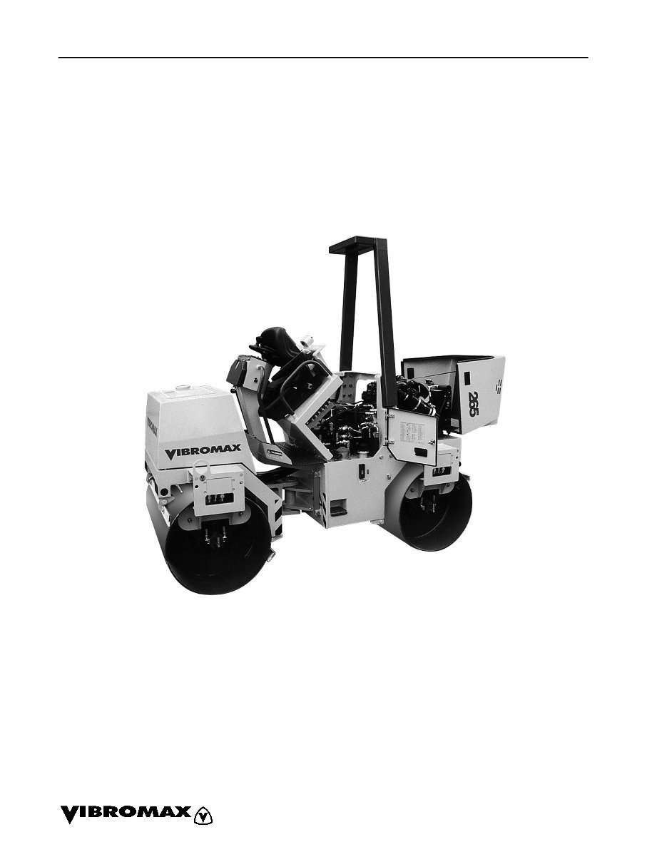
SM61005 - SECTION ONE GENERAL INFORMATION 1 - 3 MACHINE DESCRIPTION The 255/265 Series vibratory roller is a redesign of the 253/263. The machine remains a 2.5 metric ton, tandem drum machine with articulated steering, hydrostatic drive and a hydraulically driven vibration system. The 255 has a 1000 mm (39 inch) drum width while the 265 is a 1200 mm (47 inch) drum width version. These machines are also offered with a “K” version which is a combination roller built with pneumatic tires in place of the rear drum. A Kubota D1403B, water cooled, three cylinder in-line diesel engine, mounted in the rear chassis, provides the power for the machine. The standard engine has a 29.0 Net Horse Power rating at 2600 RPM. An optional high horsepower Kubota D1403B (37 horsepower) is also available. Both engines meet the latest exhaust emissions standards. A Sauer Sunstrand hydrostatic propulsion pump provides oil for the front and rear Poclain, fixed displacement, drum drive motors in a parallel path. On the “K” model combination roller there are three propulsion motors in parallel. Propulsion system controls are enhanced with the addition of a high and low operating range. The motors are located on the right hand side of the drums and are connected directly to the drum. The vibration system consists of a fixed displacement gear pump mounted to the back of the propulsion pump. This gear pump drives the two gear motors (one on each drum, left hand side) in a series flow path, with options of vibration to the front drum only, rear drum only, both drums or neither drum. Oil from the vibration circuit passes through an air to oil cooler at the engine radiator. The exciter shafts and the drum bearings are oil lubricated, eliminating the need for grease zerks. Pressure testing of the hydraulic system has been simplified by the location of a test station inside the left side access door. Pressure testing of the drive, charge, vibratory and steering systems can be performed from this one location.
SM61005 - SECTION ONE GENERAL INFORMATION 1 - 4 Front and rear parking brakes are provided on the 255/265. The drum brakes are inte- gral to the drive motors. The brakes are spring applied / hydraulically released and are controlled by a switch on the dash and by an emergency stop switch on the right operators console. A brake release valve and a brake hand pump are located under the hood on the left side of the machine. These items provide for brake release when towing a disabled machine. A steering pump, mounted to the back of the vibration pump, provides oil for the steering control valve and a single steering cylinder at the articulation joint. The joint is maintenance free, providing 40 degrees of articulation and 15 degrees of oscillation. An articulation joint safety lock completes the steering system. The return oil flow from the vibratory circuit and the steering circuit passes through a 10 micron oil filter mounted in the top of the hydraulic reservoir. A filter bypass and a pressure differential switch completes the filter circuit. The hydraulic reservoir is located below the operators platform on the left side of the rear chassis. The electrical system consists of the stan- dard starter, battery and charging circuit along with optional lighting, hazard and directional lights. The instrument panel includes switches for vibration, sprinklers, lights and brakes along with the standard instrument cluster of warning lights and an hour meter. An emergency stop button is located right of the operator’s seat. All elec- trical fuses and relays are located behind a door panel on the right side of the opera- tors platform. A 53 gallon water tank is located on the front chassis, providing water for the asphalt sprinkler system. The tank’s modu- lar design allows for easy removal if neces- sary. On the “K” model combination roller the water tank has two separate compart- ments and the system has two water pumps to allow for the use of a special spray on the pneumatic tires. Pressurized sprinkler bars with spray nozzles on each drum, or tires on the “K” model, complete the water system. Spring loaded scrapers are provided on the front and rear of each drum. This arrangement keeps a constant scraper pressure against the drum.
You're Reading a Preview
What's Included?
Lifetime Access
Fast Download Speeds
Online & Offline Access
Access PDF Contents & Bookmarks
Full Search Facility
Print one or all pages of your manual
$33.99
JCB Vibromax 255 265 Tandem Roller Service Repair Workshop Manual
This is a highly detailed factory service repair manual for the JCB Vibromax 255 265 Tandem Roller. The manual provides step-by-step instructions and detailed illustrations, making it suitable for both do-it-yourself enthusiasts and experienced mechanics. It covers general information, engine R and I, electrical circuits, hydraulic systems, power train, parking brake system, vibration system, steering system, chassis, attachments, and more.
The manual comes in PDF format, compatible with all versions of Windows and Mac. It is designed to be easily printable and can be used with Adobe Reader and Win.
With this repair manual, you can efficiently maintain your vehicle without unnecessary expenses. Instant access is available, allowing you to make informed decisions without delay.
Reviews
Q&A
Recently Viewed
5,521,897Happy Clients
2,594,462eManuals
1,120,453Trusted Sellers
15Years in Business
Price:
Actual Price:
JCB Vibromax 255 265 Tandem Roller Service Repair Workshop Manual