


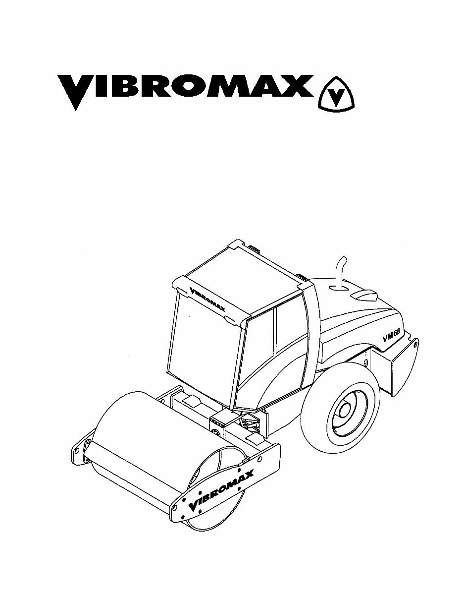
SERVICE MANUAL SM86066
SINGLE DRUM ROLLER
June 2004
Model VM 66
CALIFORNIA
Proposition 65 Warning
Diesel engine exhaust and some of its constituents are known
to the State of California to cause cancer, birth defects, and
other reproductive harm.

1
SECTION ONE
GENERAL INFORMATION
MACHINE DESCRIPTION ............................................................................... 1 - 3
SERIAL NUMBERS............................................................................... 1 - 5
IDENTIFYING MACHINE COMPONENTS ........................................... 1 - 6
FLUID SPECIFICATIONS ................................................................................ 1 - 7
MACHINE SPECIFICATIONS.......................................................................... 1 - 8
STANDARD TORQUE DATA.............................................................. 1 - 10
DIESEL FUEL SPECIFICATION ......................................................... 1 - 12
ENGINE OIL SPECIFICATION ...................................................................... 1 - 13
SAFETY, GENERAL ...................................................................................... 1 - 14
SPARK ARRESTER ...................................................................................... 1 - 14
PERSONAL.................................................................................................... 1 - 15
MACHINE OPERATION ................................................................................ 1 - 16
MAINTENANCE ............................................................................................. 1 - 19
MAINTENANCE SCHEDULE ........................................................................ 1 - 23
SECTION TWO
ENGINE
CUMMINS ENGINE WARRANTY.................................................................... 2 - 2
SECTION THREE
ELECTRICAL
GENERAL INFORMATION .............................................................................. 3 - 3
FUSES ............................................................................................................. 3 - 4
RELAYS ........................................................................................................... 3 - 5
INSTRUMENT PANEL ..................................................................................... 3 - 6
UNDERSTANDING ELECTRICAL SCHEMATICS ........................................ 3 - 11
UNDERSTANDING RELAYS......................................................................... 3 - 14
STARTER/CHARGING CIRCUIT .................................................................. 3 - 17
EMERGENCY STOP ..................................................................................... 3 - 17
UNDERSTANDING BATTERIES ................................................................... 3 - 17
UNDERSTANDING ALTERNATORS ............................................................ 3 - 19
UNDERSTANDING STARTERS.................................................................... 3 - 22
INSTRUMENTATION PANEL ........................................................................ 3 - 27
BRAKE SWITCH ............................................................................................ 3 - 29
HIGH SPEED CIRCUIT ................................................................................. 3 - 31
VIBRATION CIRCUIT .................................................................................... 3 - 33
ROAD LIGHTING CIRCUIT ........................................................................... 3 - 35

2
WORK LIGHTS & ACCESSORY PLUG ........................................................ 3 - 37
CAB CIRCUITS .............................................................................................. 3 - 39
ELECTRICAL SCHEMATICS ........................................................................ 3 - 40
PLUG CONNECTORS ................................................................................... 3 - 48
INSTRUMENT HARNESS 7242/80435 ......................................................... 3 - 49
WIRE CHART 7242/80435 ............................................................................ 3 - 51
RELAY/FUSE HARNESS 7242/80415 .......................................................... 3 - 54
WIRE CHART 7242/80415 ............................................................................ 3 - 56
REAR HARNESS 7222/80510 ....................................................................... 3 - 60
WIRE CHART 7222/80510 ............................................................................ 3 - 62
SECTION FOUR
HYDRAULIC
HYD. COOLER LINES ..................................................................................... 4 - 2
HYD. DRAIN LINES ......................................................................................... 4 - 5
HYD. CHARGE SYSTEM ................................................................................ 4 - 7
HYD. TEST STATION ...................................................................................... 4 - 9
HYDRAULIC TEST FITTINGS ....................................................................... 4 - 10
PROPULSION SYSTEM ................................................................................ 4 - 11
PROPULSION SCHEMATIC ......................................................................... 4 - 13
PROPULSION SYSTEM DIAGNOSTICS ...................................................... 4 - 15
VIBRATION SYSTEM .................................................................................... 4 - 17
VIBRATION FREQUENCY ............................................................................ 4 - 21
VIBRATION AMPLITUDE .............................................................................. 4 - 23
VIBRATORY SYSTEM DIAGNOSTICS ......................................................... 4 - 24
STEERING SYSTEM ..................................................................................... 4 - 25
STEERING SYSTEM SCHEMATIC............................................................... 4 - 27
PARKING BRAKE SYSTEM .......................................................................... 4 - 29
PARKING BRAKE SCHEMATIC.................................................................... 4 - 31
TOWING YOUR MACHINE ........................................................................... 4 - 33
TOWING PROCEDURE...................................................................... 4 - 34
PUMP CONTROL VALVE.............................................................................. 4 - 35
HYDRAULIC COMPONENTS........................................................................ 4 - 37
HYDRAULIC SCHEMATIC ............................................................................ 4 - 38
SECTION FIVE
POWER TRAIN
DRUM ASSEMBLY .......................................................................................... 5 - 2
DRUM REMOVAL ............................................................................................ 5 - 7
DRUM INSTALLATION.................................................................................... 5 - 7
RIGHT SIDE BEARING COVER...................................................................... 5 - 8

3
DRUM DRIVE BEARING REMOVAL ............................................................... 5 - 8
DRUM DRIVE BEARING ASSEMBLY ........................................................... 5 - 10
DRUM DRIVE MOTOR REPAIRS ................................................................. 5 - 11
DRUM DRIVE GEARBOX.............................................................................. 5 - 12
GFT 17 T2/312 2 GEARBOX ......................................................................... 5 - 14
SECTION SIX
PARKING BRAKE SYSTEM
PARKING BRAKE SYSTEM ............................................................................ 6 - 2
PARKING BRAKE SCHEMATIC...................................................................... 6 - 4
TOWING YOUR MACHINE ............................................................................. 6 - 6
TOWING PROCEDURE........................................................................ 6 - 7
SECTION SEVEN
VIBRATION SYSTEM
LIFTING DEVICE ............................................................................................. 7 - 2
DRUM EXCITER SHAFT ................................................................................. 7 - 3
VIBRATION SYSTEM ...................................................................................... 7 - 4
VIBRATION FREQUENCY .............................................................................. 7 - 8
VIBRATION AMPLITUDE ................................................................................ 7 - 9
VIBRATORY SYSTEM DIAGNOSTICS ......................................................... 7 - 10
DRUM DRAWING .......................................................................................... 7 - 11
DRUM - LEFT SIDE ....................................................................................... 7 - 12
DRUM - RIGHT SIDE..................................................................................... 7 - 15
DRUM REMOVAL .......................................................................................... 7 - 18
DRUM INSTALLATION.................................................................................. 7 - 18
RIGHT SIDE BEARING COVER.................................................................... 7 - 19
EXCITER BEARING REMOVAL .................................................................... 7 - 20
EXCITER BEARING ASSEMBLY .................................................................. 7 - 22
SECTION EIGHT
STEERING SYSTEM
STEERING SYSTEM ....................................................................................... 8 - 2
STEERING SYSTEM SCHEMATIC................................................................. 8 - 4
SPECIAL TOOLS............................................................................................. 8 - 6
ARTICULATION JOINTS ................................................................................. 8 - 7
JOINT DISASSEMBLY .................................................................................... 8 - 9
JOINT ASSEMBLY ........................................................................................ 8 - 13

4
SECTION NINE
CHASSIS
SECTION TEN
ATTACHMENTS
ROLL OVER PROTECTION STRUCTURE (ROPS) ..................................... 10 - 2
ROPS TIGHTENING TORQUES) ....................................................... 10 - 2

June 2004 1 - 1
SECTION ONE
GENERAL INFORMATION

1 - 2 June 2004
SM86066 - SECTION ONE GENERAL INFORMATION
June 2004 1 - 3
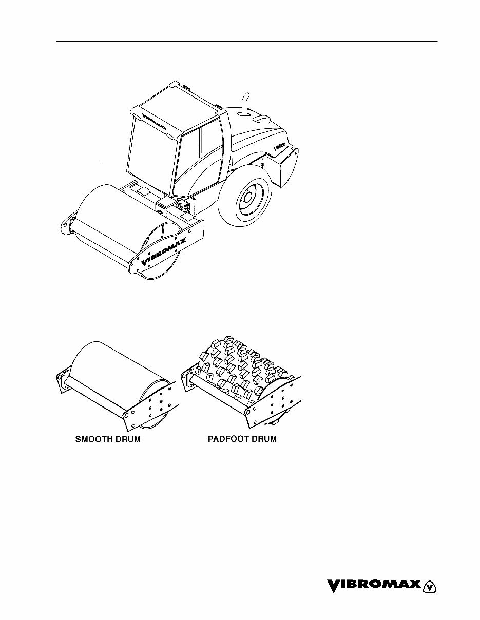
MACHINE DESCRIPTION
This book introduces the new
Vibromax 6 series single drum
rollers. Included within the pag-
es of the book are materials
covering the Model VM66.
The new roller uses the Cum-
mins 3.3 liter 4 cylinder engine.
The engine is turbocharged
and tuned to meet the latest
EPA emissions standards.
A Mannesman Rexroth vari-
able displacement, axial piston
hydrostatic pump, used for ma-
chine propulsion, is mounted to
the flywheel end of the engine.
It provides oil to a Rexroth 2
speed drum drive motor and a
2 speed axle drive motor in a
parallel path. The Rexroth
drum motor is mounted on the
left side of the drum, drives
through a L&S planetary gear-
box and is isolated from the
drum by rubber buffers. This ar-
rangement is used in the heavy
roller models with a great deal
of success. The axle drive mo-
tor is attached directly to the in-
termediate gearbox
incorporated into the rear axle.
SM86066 - SECTION ONE GENERAL INFORMATION
1 - 4 June 2004
The vibration system on the VM66 uses a
Rexroth hydrostatic pump mounted directly
behind the propulsion pump. It is similar in
design to the propulsion pump. The vibrato-
ry pump supplies oil to a Rexroth hydrostat-
ic motor mounted at the right side of the
drum. This operates at frequencies of 1740
or 2160 vibrations per minute on both the
smooth drum and pad foot versions.
A steering pump, mounted to the rear of the
vibratory pump, provides the oil needed for
steering. The steering pump also acts as
the charge pump in the propulsion and vi-
bration systems. The steering pump draws
oil from the reservoir, passes it through the
steering control valve, through the inline hy-
draulic filter, and into the charge circuit.
This machine comes standard with parking
brakes at both the front drum and the rear
axle. A spring applied-hydraulically re-
leased multi disc brake is part of the drum
drive motor gearbox. The axle uses a spring
applied hydraulically released multiple disc
brake at each axle shaft.
Pressure testing has been made easier by
placing all the test ports at a centrally locat-
ed test station under the engine hood.
The electrical system consists of a 12 volt
battery, starter, alternator system, optional
lighting and standard instrumentation.
You're Reading a Preview
What's Included?
 Lifetime Access
Fast Download Speeds
Online & Offline Access
Access PDF Contents & Bookmarks
Full Search Facility
Print one or all pages of your manual
$37.99
JCB VIBROMAX VM66 Single Drum Roller Service Repair Manual
Viewed 47 Times Today

What's Included?
Lifetime Access
Fast Download Speeds
Online & Offline Access
Access PDF Contents & Bookmarks
Full Search Facility
Print one or all pages of your manual
$37.99

Secure transaction
What's Included?
Lifetime Access
Fast Download Speeds
Online & Offline Access
Access PDF Contents & Bookmarks
Full Search Facility
Print one or all pages of your manual
Description
This comprehensive Service Manual for the JCB VIBROMAX VM66 Single Drum Roller is essential for immediate repairs. It contains detailed technical data, diagrams, and a complete list of parts. Whether you are a professional mechanic or a DIY enthusiast, this manual is a valuable resource.
- General Information
- Engine
- Electrical
- Hydraulic
- Power Train
- Parking Brake System
- Vibration System
- Steering System
- Chassis
- Attachments
This Service Manual is compatible with all versions of Windows & Mac and is available in English. It requires Adobe Reader for access. With step-by-step instructions, it is designed to assist both professional mechanics and DIY enthusiasts in performing repairs easily and effectively.


