Service Information Document Title: Function Group: Information Type: Date: Electrical system, description 300 Service Information 2015/8/31 Profile: GRD, G930B, G940B, G946B, G960B [GB] Electrical system, description The machine is equipped with a 24 VDC, negative ground electrical system. The electrical system includes electrical and electromechanical devices such as batteries, solenoid valves, switches, sensors, fuses and relays. A 30 or 60 amp converter is available to supply 12 VDC power for accessory items such as a 2-way radio, 12 V power outlet, and other options. Electric power is disconnected using a battery disconnect switch located in the left engine compartment. The battery disconnect switch disconnects the ground circuit between the grader frame and the batteries. Voltage feed is supplied through two main fuses located at the 24 V battery positive terminal. They supply voltage feed for the cab and the preheating coil. Relays and fuses are placed in the electrical distribution box behind the operator’s seat and are accessible when the cover is opened. On the inside of the cover, a decal identifies the respective relays and fuses. Before working on the electrical system, place the machine in the , and follow the instructions in the 191 Service position Safety Section of this Service Manual. Because of the wide use of electronic components on Volvo graders, extra care must be taken when troubleshooting the electrical system to prevent stray voltage spikes..
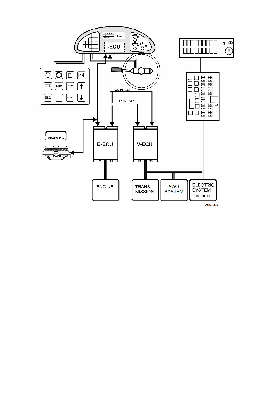
Service Information Document Title: Function Group: Information Type: Date: Electronic control system, description 300 Service Information 2015/8/31 Profile: GRD, G946B [GB] Electronic control system, description Vehicle electronics, general The machine electronics contain three units that communicate with each other through two data links. Each control unit processes values from sensors and operating controls, which help to control components so that proper function is maintained. The control units in the system include the instrument control unit I-ECU, the vehicle control unit V-ECU and the engine control unit E-ECU. The vehicle electronics facilitates trouble shooting through an extensive diagnostic system. The operator is informed of the location of the malfunction with a warning light, together with a text message. VCADS Pro is connected through the service socket located in the electrical distribution box behind the operator’s seat. The instrument control unit I-ECU is located in the instrument panel and contains software for presenting operator information on the display panel, including warnings and control lights. The control unit receives information from the other control units through the data bus. The engine control unit E-ECU contains software for controlling engine functions. The control unit receives information from the engine sensors as well as the data bus. The control unit also sends information to the other control units through the data buses. The vehicle control unit V-ECU is located near the electrical distribution box behind the operator’s seat and contains software for controlling transmission operation, AWD system operation as well as many other systems. The vehicle control unit is connected to the other control units through the data bus. Communication for programming, changing parameters, reading error codes, testing and checking components, etc, takes place using VCADS Pro.
Figure 1 Communications with ECUs
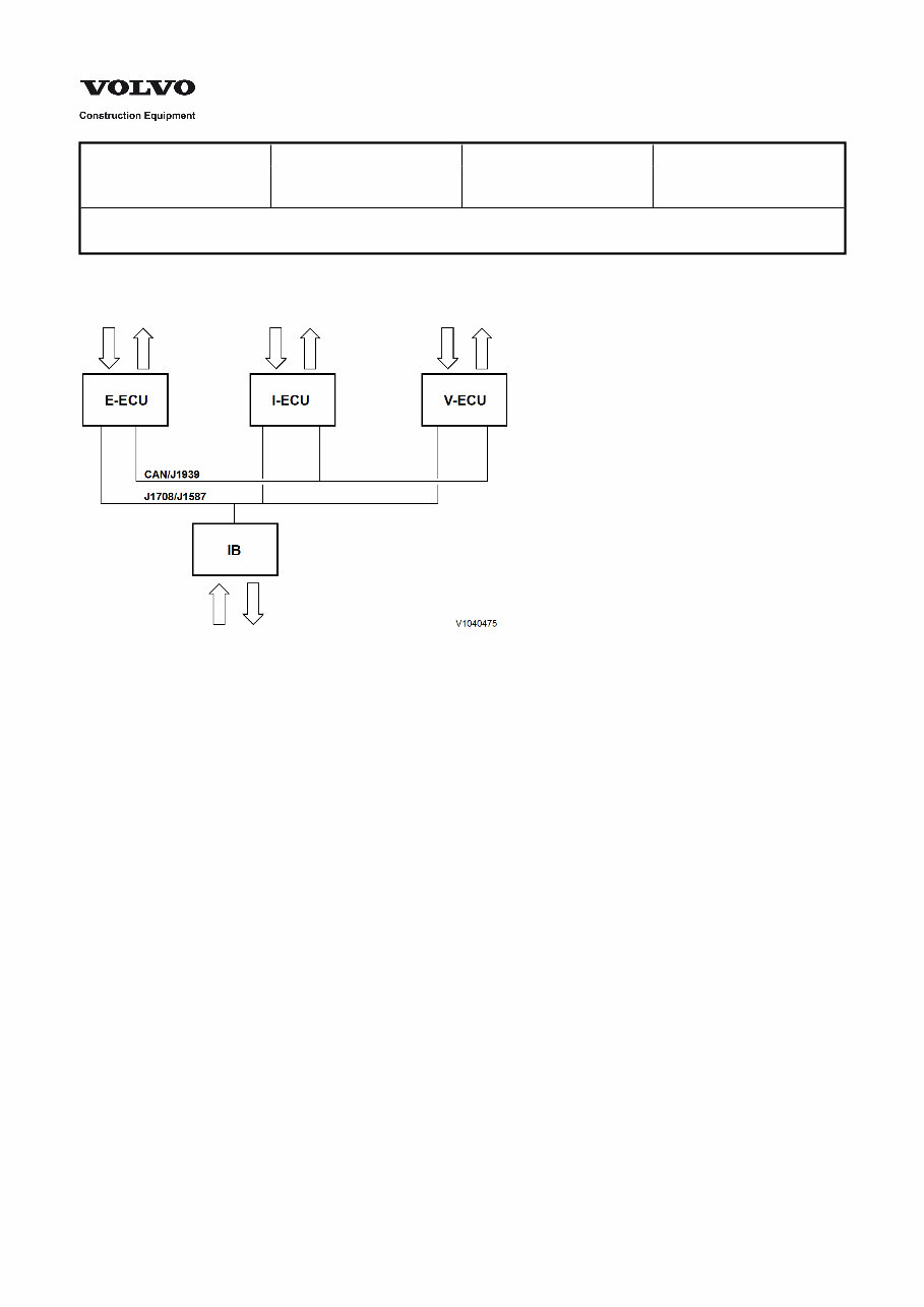
Service Information Document Title: Function Group: Information Type: Date: Communication with data buses 300 Service Information 2015/8/31 Profile: GRD, G946B [GB] Communication with data buses Figure 1 Communication E-ECU (Engine control unit) I-ECU (Instrument control unit) V-ECU (Vehicle control unit) IB (Service socket for VCADS Pro) General Vehicle electronics are based on the principle that all communication between controls units takes place through two data buses. The machine's three control units are connected to the buses to be able to communicate with each other. Communication between the different control units as well as reporting from control units to service socket takes place on data buses CAN/J1939 and J1708/J1587. The buses follow SAE standards and consist of two pair-twisted cables. The purpose of the twisted cabling is to protect the bus from electrical interference. If a malfunction should occur in the system, a signal is sent on the information bus, making it possible to read the information, either on the operator's instruments or through VCADS Pro. The figure shows the principle for how the control units and service socket are connected to the buses. CAN/J1939 Control bus System control signals are sent through this bus. The control bus is very quick, which is necessary for control of the entire system to work and quickly adapt to changing conditions. The main communication alternative is the CAN/J1939 bus. However, for E–ECU, some control data is only sent on the J1708/J1587 bus J1708/J1587 information bus The information bus is connected to the control units and service socket. Information and diagnostic signals are sent on this bus. In addition, some control data is sent from the engine control unit through this bus.
The bus also functions as a "back-up" for the control bus, if it should fail for some reason. The system status is continuously updated and available for reading through the information bus. By connecting VCADS Pro to the service socket, it's possible to read error codes, perform tests, empty logged information, download parameters and download software.
Service Information Document Title: Function Group: Information Type: Date: Software 300 Service Information 2015/8/31 Profile: GRD, G930B, G940B, G946B, G960B [GB] Software Software is stored in the control units E-ECU, I-ECU and V-ECU. To determine which software is installed in the machine, the part number is read off from the software (Main software and Data sets) in the machine control units Contronic instrument display electrical menu. Also, the part number of the software (Main software and Data Sets) can be read off using VCADS Pro. Updating of the machine's software is handled through release of a new edition. The releases are designated with Year: edition, for example, R2004:5 and gets a new part number. Updating of software for control units takes place through downloading of new software from VOLVO with VCADS Pro.
Service Information Document Title: Function Group: Information Type: Date: Software versions and ECUs/part number, general 300 Service Information 2015/8/31 Profile: GRD, G930B, G940B, G946B, G960B [GB] Software versions and ECUs/part number, general Updating of the machine's software is handled by release of new version (edition). Versions are designated with “V.year.edition.extra edition, e.g., “V2003.2.0”. A maximum six ordinary versions are released per year. The ordinary versions are designated with 0 as last digit. If needed, any extra versions can be released between the ordinary versions. These are designated with 1 or higher as last digit. To determine which version is installed in the machine, the part number of the software in the machine's control units (ECU/ MID) is checked. Part numbers can be read out in the following way (see ): 300 Software versions and ECUs/part number, checking Information panel (only Main software = Main software, MSW) Service tool VCADS Pro Then compare read out part numbers with the version table, see . The 300 Software versions and ECUs/part number, list version table describes with part number which hardware (ECU) and software (main software and data sets) that are included in each version. Read out from the table which version is installed in the machine. Function descriptions that are changed in a version are described with the variants that occur. Variants are marked with version association. From the version descriptions, see e.g., , it is clear when (from serial number) a version is 300 V2007.5.0, change specification introduced for each model. From this, in most cases it is possible to read out which version was installed in the machine when delivered from the factory. Some versions do not have descriptions since the content in these versions do not affect functionality in the machine. NOTE! A later version than the one at delivery may be installed in the machine! Always check the software part numbers and compare to the current version table. Updating to new version in machine is done with service tool VCADS Pro. NOTE! For information on later versions, contact Customer Support. Abbreviations used in the version tables: HW Hardware MSW Software (main software) DST1 Data set 1 (data set 1) DST2 Data set 2 (data set 2)
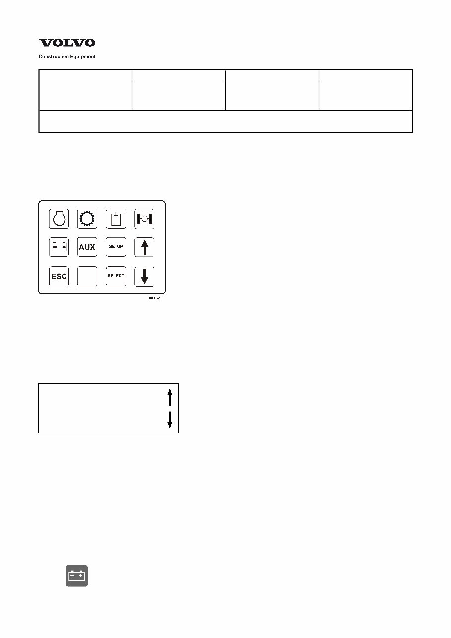
Service Information Document Title: Function Group: Information Type: Date: Software versions and ECUs/part number, checking 300 Service Information 2015/8/31 Profile: GRD, G930B, G940B, G946B, G960B [GB] Software versions and ECUs/part number, checking Checking Machine information from the Instrument Display Unit Information about the Software Versions, ECUs and part numbers is obtained with the aid of the keyboard located on the pedestal instrument display panel in the machine cab. Refer to “Instrument panels, - Display unit” section in the Machine Operator's Manual. Figure 1 Keyboard for Display unit By pressing the respective function key on the keyboard, information about the machine status is displayed on the screen. Should more than one screen be available for a function group, directional arrows will be displayed on the right side of the screen. To browse within a function group, press the arrow down key to move to the next information screen or press the arrow up key to return to the previous screen. Figure 2 Display screen, directional arrows, (indicates up or down to next information screen) NOTE! If “Er” is shown for a value in any display screen, it indicates and error in the signal monitoring that information. NOTE! Features that are options will not appear in the display unless the machine is equipped with that option. To check Machine Software information: 1. Activate the machine software information display screen by pressing the Electrical System key on the display unit keyboard.
2. 3. 4. 5. 6. Figure 3 Electrical System, key The Electrical System display screen will appear displaying the system voltage. ...... ELECTRICAL SYSTEM ...... VOLTAGE XX.X V X = Electrical system voltage (real time) in volts DC. Browse to the next screen by pressing the arrow-down key on the keyboard. The Instrument electronic control unit displays the following I-ECU information: ...... IECU SOFTWARE VER ...... MSW: XXXXXXXXXXX DIST1: YYYYYYYYYYY DIST2: ZZZZZZZZZZZ X = Main software: (MSW) / Er. Y = Dataset 1: (DST1) / Er. Z = Dataset 2: (DST2) / Er. Browse to the next screen by pressing the arrow-down key on the keyboard. The Vehicle electronic control unit display screen displays the following V-ECU information: ...... VECU SOFTWARE VER ...... MSW: XXXXXXXXXXX DIST1: YYYYYYYYYYY DIST2: ZZZZZZZZZZZ X = Main software: (MSW) / Er. Y = Dataset 1: (DST1) / Er. Z = Dataset 2: (DST2) / Er. Browse to the next screen by pressing the arrow-down key on the keyboard. The Engine electronic control unit display screen displays the following E-ECU information: ...... EECU SOFTWARE VER ...... MSW: XXXXXXXXXXX DIST1: YYYYYYYYYYY DIST2: ZZZZZZZZZZZ X = Main software: (MSW) / Er. Y = Dataset 1: (DST1) / Er. Z = Dataset 2: (DST2) / Er. Browse to the previous display screens by pressing the arrow-up key on the keyboard. After checking the machine information, return the display back to the “Operating information” screen by pressing the ESC key. NOTE! Pressing the ESC key returns the display to the “Operating information” mode, regardless of which menu screen is showing. (Except when in SETUP mode). Refer to the Operator's Manual for further instructions on using the Display unit keyboard and for accessing information in other function group modes.
Figure 4 ESC = Escape/return Checking Vehicle information using the VCADS Pro service tool Detailed Vehicle Information is obtained using the VCADS Pro service tool. For further information and instructions refer to: . 301 VCADS Pro, 17034-3 - Vehicle information, test
The VOLVO G960B MOTOR GRADER Workshop Service Repair Manual is an essential resource for professional technicians and do-it-yourself mechanics alike. This comprehensive manual provides in-depth guidance for repairing and maintaining the VOLVO G960B MOTOR GRADER, covering all styles and models.
Featuring easy-to-read text sections, high-quality diagrams, and step-by-step instructions, this manual equips both novice and experienced mechanics with the knowledge to efficiently perform repairs. It covers critical specifications, disassembly, assembly, cleaning, and reinstalling procedures, ensuring that every detail of the machine is addressed.
Whether you opt for a paper manual or the digital version, you will have access to the same features, including step-by-step repair procedures, illustrations, maintenance guidelines, and more. The digital version offers the added convenience of instant access without any shipping fees, allowing you to address repair needs promptly.
Product Details:
Manual: VOLVO G960B MOTOR GRADER Workshop Service Repair Manual
File Format: PDF
Language: English
Specifications: Full Printable
Zoom IN/OUT: Yes
Delivery: Instant
Requirements: Adobe Reader & Win
Compatible: All Versions of Windows & Mac
What is a Service Manual? It is a book that provides instant access to comprehensive repair and maintenance guidance without the need for additional software or waiting time. If any issues arise, customer support is readily available to assist you.
User Tags:
VOLVO G960B MOTOR GRADER General Information
VOLVO G960B MOTOR GRADER Routine Maintenance
VOLVO G960B MOTOR GRADER Care and Safety
Body and Framework
VOLVO G960B MOTOR GRADER Standard Parts, Service
VOLVO G960B MOTOR GRADER Engine with Mounting and Equipment
VOLVO G960B MOTOR GRADER Elec. System, Warning System, Information System, Instruments
VOLVO G960B MOTOR GRADER Power Transmission
VOLVO G960B MOTOR GRADER Brake
VOLVO G960B MOTOR GRADER Steering
VOLVO G960B MOTOR GRADER Frame and Wheel
VOLVO G960B MOTOR GRADER Machinery House, Cab, Exterior Trim Parts Anywhere
VOLVO G960B MOTOR GRADER Hydraulic System
VOLVO G960B MOTOR GRADER Hydraulic and Electric schematics
Thank you for considering this comprehensive manual for your VOLVO G960B MOTOR GRADER repair and maintenance needs.