Komatsu GD650A-2CY Motor Grader Workshop Service Manual
What's Included?
Lifetime Access
Fast Download Speeds
Online & Offline Access
Access PDF Contents & Bookmarks
Full Search Facility
Print one or all pages of your manual
December 2002 Copyright 2002 Komatsu DataKom Publishing Division CEBM009900 Shop Manual GD530A(W)-2B(C)Y GD650A(W)-2B(C)Y GD670A(W)-2B(C)Y MOTOR GRADER This material is proprietary to Komatsu America International Company and is not to be reproduced, used, or disclosed except in accordance with written authorization from Komatsu America International Company. It is our policy to improve our products whenever it is possible and practical to do so. We reserve the right to make changes or add improvements at any time without incurring any obligation to install such changes on products sold previously. Due to this continuous program of research and development, periodic revisions may be made to this publication. It is recommended that customers contact their distributor for information on the latest revision. SERIAL NUMBERS GD530A-2BY GD530A-2CY GD530AW-2BY GD530AW-2CY 203481 203201 210242 203290 and UP GD650A-2BY GD650A-2CY GD650AW-2BY GD650AW-2CY 202556 202642 203328 202662 GD670A-2BY GD670A-2CY GD670AW-2BY GD670AW-2CY 203282 202681 203338 203234 GD530/650/670A(W)-2B(C)Y
GD530/650/670(W)-2BY Publinfok.fm 12/13/02 PRODUCT PUBLICATIONS INFORMATION Various product Parts and Service Publications are available to all KOMATSU construction equipment owners, including operation and maintenance manuals, parts books and service manuals. Special publications, such as service tool, air conditioning and turbocharger service manuals are also available as well as selected Operation and Service manuals in foreign languages. The Publications listed below are available for this particular machine(s). DESCRIPTION FORM NUMBER PARTS BOOK - PAPER: Chassis and Engine GD530 . . . . . . . . . . . . . . . . . . . . . . . . . . . . . . . . . . . BEPB002900 Chassis and Engine GD650 . . . . . . . . . . . . . . . . . . . . . . . . . . . . . . . . . . . BEPBG65091 Chassis and Engine GD670 . . . . . . . . . . . . . . . . . . . . . . . . . . . . . . . . . . . BEPBG67100 OPERATION AND MAINTENANCE MANUAL: Chassis and Engine . . . . . . . . . . . . . . . . . . . . . . . . . . . . . . . . . . . . . . . . . CEAM009700 SHOP MANUAL Chassis . . . . . . . . . . . . . . . . . . . . . . . . . . . . . . . . . . . . . . . . . . . . . . . . . . CEBM009900 Engine 114E-2 Series . . . . . . . . . . . . . . . . . . . . . . . . . . . . . . . . . . . . . . . CEBM000601 Engine 102E-2 Series . . . . . . . . . . . . . . . . . . . . . . . . . . . . . . . . . . . . . . . . SEBM010011 SAFETY MANUAL Machine specific . . . . . . . . . . . . . . . . . . . . . . . . . . . . . . . . . . . . . . . . . . . . . 1085 960 R2 Parts and Service Publications can only be acquired by authorized KOMATSU distributors using the Komatsu America International Company Parts Inventory Processing System (PIPS) or the Extranet Literature Ordering System. If the PIPS system is not available at the distributor location, then the following Requisition for Technical Service Publications and Service Forms can be used. Form KDC91E is shown on the reverse side of this page.
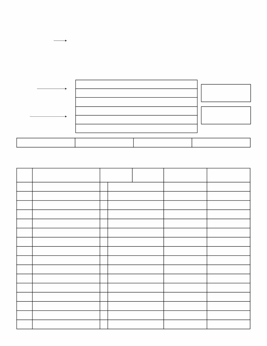
REQUISITION FOR TECHNICAL SERVICE PUBLICATIONS AND SERVICE FORMS IMPORTANT - TO ASSURE SHIPMENT OF THE CORRECT PUBLICATION(S), THE MODEL NUMBER AND MACHINE SERIAL NUMBER MUST BE SHOWN. KDC91E 040202 CURRENT PRICES WILL BE CHARGED COMPLETE FORM AND RETURN TO DataKom Publishing Division 440 North Fairway Drive Vernon Hills, IL 60061-8112 U.S.A. Attn: Service Publications Fax No. (847) 970-4186 Tel No. (847) 970-5887 SHIP TO COMPANY NAME PURCHASE ORDER NO. TYPE or PRINT ONLY ATTN. STREET ADDRESS ORDER DATE CITY, STATE, ZIP CODE COUNTRY PHONE NO. FAX NO. SHIPPING METHOD DISTR/BRANCH CODE QTY. PUBLICATION FORM NO. PARTS BOOK PUBLICATION DESCRIPTION MODEL NUMBER SERIAL NUMBER ➥ P-Paper M-Microfiche
FOREWORD SAFETY GD530/650/670A(W)-2B(C)Y 00-3 12 SAFETY 00 SAFETY NOTICE 00 GENERAL PRECAUTIONS 00 Mistakes in operation are extremely dangerous. Read the OPERATION & MAINTENANCE MANUAL carefully BEFORE operating the machine. 1. Before carrying out any greasing or repairs, read all the precautions given on the decals which are fixed to the machine. 2. When carrying out any operation, always wear safety shoes and helmet. Do not wear loose work clothes, or clothes with buttons missing. Always wear safety glasses when hitting parts with a hammer. Always wear safety glasses when grinding parts with a grinder, etc. 3. If welding repairs are needed, always have a trained, experienced welder carry out the work. When carrying out welding work, always wear welding gloves, apron, glasses, cap and other clothes suited for welding work. 4. When carrying out any operation with two or more workers, always agree on the operating procedure before starting. Always inform your fellow workers before starting any step of the operation. Before starting work, hang UNDER REPAIR signs on the controls in the operator’s compartment. 5. Keep all tools in good condition and learn the correct way to use them. 6. Decide a place in the repair workshop to keep tools and removed parts. Always keep the tools and parts in their correct places. Always keep the work area clean and make sure that there is no dirt or oil on the floor. Smoke only in the areas provided for smoking. Never smoke while working. PREPARATIONS FOR WORK 00 1. Before adding oil or making repairs, park the machine on hard, level ground, and block the wheels or tracks to prevent the machine from moving. 2. Before starting work, lower blade, ripper, bucket or any other work equipment to the ground. If this is not possible, insert the safety pin or use blocks to prevent the work equipment from falling. In addition, be sure to lock all the control levers and hang warning signs on them. 3. When disassembling or assembling, support the machine with blocks, jacks or stands before starting work. IMPORTANT SAFETY NOTICE 00 Proper service and repair is extremely important for the safe operation of your machine. The service and repair techniques recommended and described in this manual are both effective and safe methods of operation. Some of these operations require the use of tools specially designed for the purpose. To prevent injury to workers, the symbols and are used to mark safety precautions in this manual. The cautions accompanying these symbols should always be followed carefully. If any dangerous situation arises or may possibly arise, first consider safety, and take the necessary actions to deal with the situation.
FOREWORD SAFETY 00-4 GD530/650/670A(W)-2B(C)Y 4. Remove all mud and oil from the steps or other places used to get on and off the machine. Always use the handrails, ladders or steps when getting on or off the machine. Never jump on or off the machine. If it is impossible to use the handrails, ladders or steps, use a stand to provide safe footing. PRECAUTIONS DURING WORK 00 1. When removing the oil filler cap, drain plug or hydraulic pressure measuring plugs, loosen them slowly to prevent the oil from spurting out. Before disconnecting or removing components of the oil, water or air circuits, first remove the pressure completely from the circuit. 2. The water and oil in the circuits are hot when the engine is stopped, so be careful not to get burned. Wait for the oil and water to cool before carrying out any work on the oil or water circuits. 3. Before starting work, remove the leads from the battery. ALWAYS remove the lead from the negative (-) terminal first. 4. When raising heavy components, use a hoist or crane. Check that the wire rope, chains and hooks are free from damage. Always use lifting equipment which has ample capacity. Install the lifting equipment at the correct places. Use a hoist or crane and operate slowly to prevent the component from hitting any other part. Do not work with any part still raised by the hoist or crane. 5. When removing covers which are under internal pressure or under pressure from a spring, always leave two bolts in position on opposite sides. Slowly release the pressure, then slowly loosen the bolts to remove. 6. When removing components, be careful not to break or damage the wiring, Damaged wiring may cause electrical fires. 7. When removing piping, stop the fuel or oil from spilling out. If any fuel or oil drips on to the floor, wipe it up immediately. Fuel or oil on the floor can cause you to slip, or can even start fires. 8. As a general rule, do not use gasoline to wash parts. In particular, use only the minimum of gasoline when washing electrical parts. 9. Be sure to assemble all parts again in their original places. Replace any damaged part with new parts. When installing hoses and wires, be sure that they will not be damaged by contact with other parts when the machine is being operated. 10. When installing high pressure hoses, make sure that they are not twisted. Damaged tubes are dangerous, so be extremely careful when installing tubes for high pressure circuits. Also check that connecting parts are correctly installed. 11. When assembling or installing parts, always use the specified tightening torques. When installing protective parts such as guards, or parts which vibrate violently or rotate at high speed, be particularly careful to check that they are installed correctly. 12. When aligning two holes, never insert your fingers or hand. Be careful not to get your fingers caught in a hole. 13. When measuring hydraulic pressure, check that the measuring tool is correctly assembled before taking any measurements. 14. Take care when removing or installing the tracks of track-type machines. When removing the track, the track separates suddenly, so never let anyone stand at either end of the track.
FOREWORD GENERAL GD530/650/670A(W)-2B(C)Y 00-5 12 GENERAL 00 This shop manual has been prepared as an aid to improve the quality of repairs by giving the serviceman an accurate understanding of the product and by showing him the correct way to perform repairs and make judgements. Make sure you understand the contents of this manual and use it to full effect at every opportunity. This shop manual mainly contains the necessary technical information for operations performed in a service workshop. For ease of understanding, the manual is divided into the following sections. These sections are further divided into each main group of components. GENERAL This section lists the general machine dimensions, performance specifications, component weights, and fuel, coolant and lubricant specification charts. STRUCTURE AND FUNCTION This section explains the structure and function of each component. It serves not only to give an understanding of the structure, but also serves as reference material for troubleshooting. TESTING, ADJUSTING AND TROUBLESHOOTING This section explains checks to be made before and after performing repairs, as well as adjustments to be made at completion of the checks and repairs. Troubleshooting charts correlating Problems to Causes are also included in this section. DISASSEMBLY AND ASSEMBLY This section explains the order to be followed when removing, installing, disassembling or assembling each component, as well as precautions to be taken for these operations. MAINTENANCE STANDARD This section gives the judgement standards when inspecting disassembled parts. NOTICE The specifications contained in this shop manual are subject to change at any time and without any advance notice. Contact your distributor for the latest information.
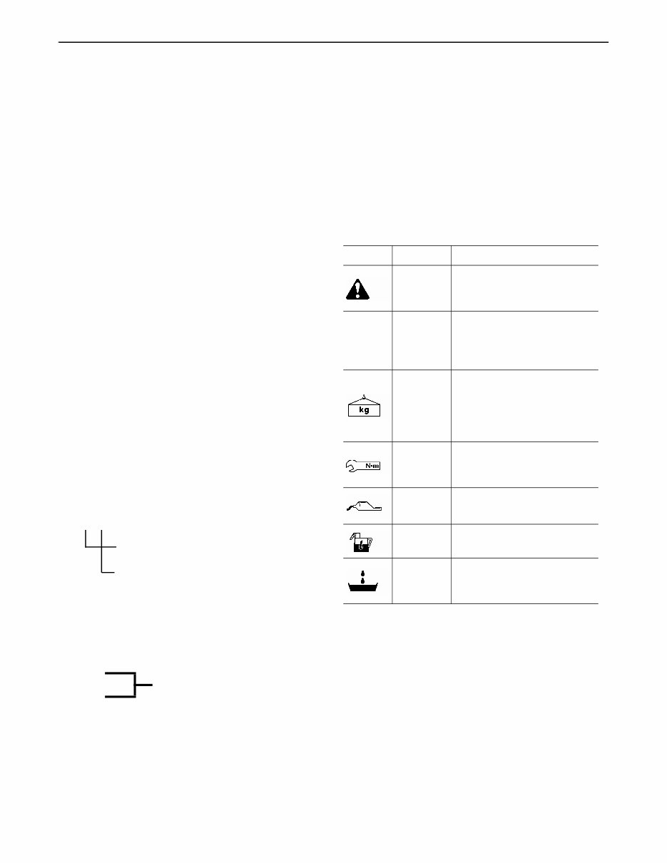
FOREWORD HOW TO READ THE SHOP MANUAL 00-6 GD530/650/670A(W)-2B(C)Y 12 HOW TO READ THE SHOP MANUAL 00 VOLUMES 00 Shop manuals are issued as a guide to carrying out repairs. They are divided as follows: Chassis volume: Issued for every machine model Engine volume: Issued for each engine series Electrical volume: Each issued as one to cover all models Attachment volume: Each issued as one to cover all models These various volumes are designed to avoid duplication of information. Therefore to deal with all repairs for any model, it is necessary that chassis, engine, electrical and attachment be available. DISTRIBUTION AND UPDATING 00 Any additions, amendments or other changes will be sent to your distributors. Get the most up-to-date information before you start any work. FILING METHOD 00 1. See the page number on the bottom of the page. File the pages in correct order. 2. Following examples show how to read the page number: Example: 10 - 3 Item number (10. Structure and Function) Consecutive page number for each item 3. Additional pages: Additional pages are indicated by a hyphen (-) and numbered after the page number. File as in the example. Example: REVISED EDITION MARK 00 When a manual is revised, an edition mark (123) is recorded on the bottom outside corner of the pages. REVISIONS 00 Revised pages are shown at the LIST OF REVISED PAGES between the title page and SAFETY page. SYMBOLS 00 So that the shop manual can be of ample practical use, important places for safety and quality are marked with the following symbols. 10-4 10-4-1 Added pages 10-4-2 10-5 Symbol Item Remarks Safety Special safety precautions are necessary when performing the work. ★ Caution Special technical precautions or other precautions for preserving standards are necessary when performing the work. Weight Weight of parts or systems. Caution necessary when selecting hoisting wire or when working posture is important, etc. Tightening torque Places that require special attention for tightening torque during assembly. Coat Places to be coated with adhesives and lubricants etc. Oil, water Places where oil, water or fuel must be added, and the capacity. Drain Places where oil or water must be drained, and quantity to be drained.
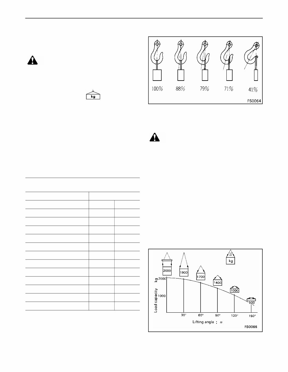
FOREWORD HOISTING INSTRUCTIONS GD530/650/670A(W)-2B(C)Y 00-7 12 HOISTING INSTRUCTIONS 00 HOISTING 00 ● If a part cannot be smoothly removed from the machine by hoisting, the following checks should be made: 1. Check for removal of all bolts fastening the part to the relative parts. 2. Check for existence of another part causing interface with the part to be removed. WIRE ROPES 00 1. Use adequate ropes depending on the weight of parts to be hoisted, referring to the table below: ★ The allowable load value is estimated to be 1/6 or 1/7 of the breaking strength of the rope used. 2. Sling wire ropes from the middle portion of the hook. Slinging near the edge of the hook may cause the rope to slip off the hook during hoisting, and a serious accident can result. Hooks have maximum strength at the middle portion. 3. Do not sling a heavy load with one rope alone, but sling with two or more ropes symmetrically wound on to the load. 4. Do not sling a heavy load with ropes forming a wide hanging angle from the hook. When hoisting a load with two or more ropes, the force subjected to each rope will increase with the hanging angles. The table below shows the variation of allowable load (kg) when hoisting is made with two ropes, each of which is allowed to sling up to 1000 kg vertically, at various hanging angles. When two ropes sling a load vertically, up to 2000 kg of total weight can be suspended. This weight becomes 1000 kg when two ropes make a 120 hanging angle. On the other hand, two ropes are subject to an excessive force as large as 4000 kg if they sling a 2000 kg load at a lifting angle of 150 WARNING! Heavy parts (25 kg or more) must be lifted with a hoist etc. In the DISASSEMBLY AND ASSEMBLY section, every part weighing 25 kg or more is indicated clearly with the symbol Wire ropes (Standard Z or S twist ropes without galvanizing) Rope diameter Allowable load mm kN tons 10 9.8 1.0 11.2 13.7 1.4 12.5 15.7 1.6 14 21.6 2.2 16 27.5 2.8 18 35.3 3.6 20 43.1 4.4 22.4 54.9 5.6 30 98.1 10.0 40 176.5 18.0 50 274.6 28.0 60 392.2 40.0 WARNING! Slinging with one rope may cause turning of the load during hoisting, untwisting of the rope, or slipping of the rope from its original winding position on the load, which can result in a dan- gerous accident
FOREWORD COATING MATERIALS 00-8 GD530/650/670A(W)-2B(C)Y 12 COATING MATERIALS 00 ★ The recommended coating materials prescribed in the shop manuals are listed below. Category Code Part No. Quantity Container Main applications, features Adhesives LT-1A 790-129-9030 150 g Tube ● Used to prevent rubber gaskets, rubber cushions and cork plugs from coming out LT-1B 790-129-9050 20 g (2 pes.) Polyethylene container ● Used in places requiring an immediately effective, strong adhesive. ● Used for plastics (except polyethylene, polypropylene, tetrafluoroethylene, and vinyl chloride), rubber, metal and non-metal. LT-2 09940-00030 50 g Polyethylene container ● Features: Resistance to heat, chemicals ● Used for anti-loosening and sealant purposes for bolts and plugs. LT-3 790-129-9060 (Set of adhesive and hardening agent) Adhesive: 1 kg Hardening agent: 500 g Can ● Used as adhesive or sealant for metal, glass or plastic. LT-4 790-129-9040 250 g Polyethylene container ● Used as sealant for machined holes. Holtz MH 705 790-126-9120 75 g Tube ● Used as heat-resisting sealant for repairing engine. Three bond 1735 179-129-9140 2 g Polyethylene container ● Quick hardening type adhesive. ● Cure time: within 5 sec. to 3 min. ● Used mainly for adhesion of metals, rubbers, plastics and woods. Aron-alpha 201 790-129-9130 50 g Polyethylene container ● Quick hardening type adhesive. ● Quick cure type (max. strength after 30 minutes). ● Used mainly for adhesion of rubbers, plastics and metals. Loctite 648-50 79A-129-9110 50 cc Polyethylene container ● Features: Resistance to heat, chemicals ● Used at joint portions subject to high tempera- ture. Gasket sealant LG-1 790-129-9010 200 g Tube ● Used as adhesive or sealant for gaskets and packing of power train case, etc. LG-3 790-129-9070 1 kg Can ● Features: Resistance to heat ● Used as sealant for flange surfaces and bolts at high temperature locations; used to prevent seizure. ● Used as sealant for heat resistant gasket for at high temperature locations such as engine pre-combustion chamber, exhaust pipe.
This Komatsu GD650A-2CY Motor Grader Workshop Service Manual is designed to provide comprehensive data, characteristics, instructions, and methodology for repair interventions on the vehicle and its components. It includes special notes, important points, service data, precautions, and detailed illustrations, exploded diagrams, drawings, and photos to guide you through every service repair procedure for the Komatsu GD650A-2CY Motor Grader.
The manual is useful for both professional mechanics and DIY enthusiasts, offering comprehensive step-by-step procedures, explanations, and pictorial diagrams from bumper to bumper. It covers adjustment and repair operations, including reference to service tool numbers and wear limits, and can be viewed on any computer, zoomed, and printed. The manual is intended as a handy, easy-to-read reference book, providing general descriptions for accomplishing service and repair work with tested, effective techniques.
It outlines procedures for servicing and repairing vehicles using safe, effective methods, containing many notes, cautions, and warnings to be followed along with standard safety procedures to eliminate the possibility of personal injury or improper service which could damage the vehicle or compromise its safety.
To maximize the life of your Komatsu GD650A-2CY Motor Grader, it is essential to accurately follow the maintenance requirements, investigate unusual noises and changes in riding characteristics, use only genuine parts, follow procedures carefully, keep complete records of all maintenance and repairs, and use approved lubricants as specified in the manual.
This manual is known by various names such as Komatsu GD650A-2CY Motor Grader Service service manual, repair manual, workshop manual, and shop manual. It is designed primarily for use by trained technicians in a properly equipped workshop but contains enough detail and basic information to make it useful to the owner who desires to perform basic maintenance and repair work.
For all maintenance and repair work on the Komatsu GD650A-2CY Motor Grader, all accident prevention guidelines must be strictly observed, and a complete set of standard tools, as well as the special tools and fixtures shown and listed, are necessary. The manual also contains information about adjusting work and valuable reference data for such adjustment values.
It provides technical information regarding the design, function, disassembly, adjusting work, and troubleshooting on the components and model of the Komatsu GD650A-2CY Motor Grader, supported by photographs, notes, drawings, schematics, as well as exploded and sectional drawings to simplify any necessary repair work.
It is important to thoroughly familiarize yourself with procedures before starting work, perform all work with great care and in a clean working area with adequate lighting, and strictly observe all safety measures described in the manual. The manual is 100% complete and intact, with no missing or corrupt pages/sections.
For a complete list of tags and components covered, please refer to the manual.
Recently Viewed
5,521,897Happy Clients
2,594,462eManuals
1,120,453Trusted Sellers
15Years in Business
Price:
Actual Price:
Komatsu GD650A-2CY Motor Grader Workshop Service Manual