Volvo FC2421C Excavator Service Repair Manual INSTANT
What's Included?
Lifetime Access
Fast Download Speeds
Offline Viewing
Access Contents & Bookmarks
Full Search Facility
Print one or all pages of your manual
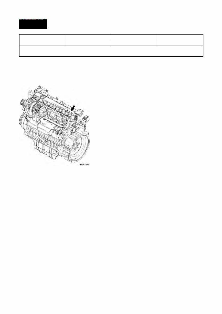
Service Information Document Title: Function Group: Information Type: Date: Engine, description 200 Service Information 2014/9/11 Profile: EXC, FC2421C [GB] Engine, description D6E - tier 3 compliant The D6E configuration is a four stroke, straight six cylinder, turbocharged, direct injected diesel engine with charge air cooling and wet, replaceable cylinder liners. The D6E engine uses a Common Rail Fuel System controlled by the engine electronic control (E-ECU) software. Electronically controlled IEGR (Internal Exhaust Gas Recirculation) reduces NOѥ formation and lowers emissions without the need for exhaust after treatment. Volvo's latest engine management system, E-ECU is used to control all engine electronic functions. The cylinders are numbered consecutively beginning at the flywheel end. Engine rotational direction is counterclockwise as seen from the flywheel end. Figure 1 Engine, D6E Watermark,businessmanaccount:"thebestmanual",Pleasedonotresell.Thankyouverymuch. Watermark,businessmanaccount:"thebestmanual",Pleasedonotresell.Thankyouverymuch.
Service Information Document Title: Function Group: Information Type: Date: Engine, identification 200 Service Information 2014/9/11 Profile: EXC, FC2421C [GB] Engine, identification Identification plate The engine model, serial number and performance data are stamped on an identification plate which is attached on the cylinder head cover. The engine model designation and serial number must be indicated when ordering spare parts. Figure 1 Engine identification, D6E Watermark,businessmanaccount:"thebestmanual",Pleasedonotresell.Thankyouverymuch. Watermark,businessmanaccount:"thebestmanual",Pleasedonotresell.Thankyouverymuch.
Service Information Document Title: Function Group: Information Type: Date: Engine, tightening torques 200 Service Information 2014/9/11 Profile: EXC, FC2421C [GB] Engine, tightening torques NOTICE Regarding bolted joints which are not listed here, see “Volvo standard tightening torques” Engine, tightening torque Rocker arm bracket on cylinder head 30 Nm (22.2 lbf ft) Cylinder head cover (M6) on cylinder head 13 Nm (9.6 lbf ft) Exhaust return module on cylinder head Step 1: 10 Nm (7.4 lbf ft) Step 2: 30 Nm (22.2 lbf ft) Lock nut, valve adjusting screw 20 ±2 Nm (14.8 ±1.5 lbf ft) Locking screw on cylinder head 34 Nm (25.2 lbf ft) Solenoid valve on cylinder head 24 Nm (17.8 lbf ft) Front cover on crankcase Step 1: 3 Nm (2.2 lbf ft) Step 2: 21 Nm (15.5 lbf ft) Drain plug on oil pan, M18 55 Nm (40.7 lbf ft) Crankcase ventilation on cylinder head 21 Nm (15.5 lbf ft) Return line to return stop valve 30 Nm (22.2 lbf ft) Return stop valve to crankcase 80 Nm (59.2 lbf ft) Impulse transmitter (crankshaft) on holder on front cover 9 Nm (6.7 lbf ft) Impulse transmitter (camshaft) on gearcase 9 Nm (6.7 lbf ft) Turbocharger on exhaust manifold 42 Nm (31.1 lbf ft) Clamping shoe injector on cylinder head 16 Nm (11.8 lbf ft) Injection lines on rail and injector, high pressure line on high-pressure pump 25 Nm (18.5 lbf ft) Fuel supply pump on holder 22 Nm (16.3 lbf ft) Holder fuel supply pump on holder 30 Nm (22.2 lbf ft) V-belt pulley on fuel supply pump 27 Nm (20.0 lbf ft) High pressure pump on crankcase, M10 Step 1: 10 Nm (7.4 lbf ft) Step 2: 50 Nm (37.0 lbf ft) Fuel control valve 30 Nm (22.2 lbf ft) Fuel pipe on high pressure pump 29 Nm (21.5 lbf ft) Fuel pipe on control block 39 Nm (28.9 lbf ft) Rail on cylinder head 30 Nm (22.2 lbf ft) Pressure relief valve on rail 100 Nm (74.0 lbf ft) Rail pressure sensor on rail 70 Nm (51.8 lbf ft) Pipe clips, fuel line fastening 30 Nm (22.2 lbf ft) Fuel line on control block, fuel filter console and rail 39 Nm (28.9 lbf ft) Fuel pipe (return) on control block 49 Nm (36.3 lbf ft) Fuel pipe (return) on cylinder head 29 Nm (21.5 lbf ft) Fuel line on fuel filter8 39 Nm (28.9 lbf ft) Fuel filter console/radiator tank on crankcase 30 Nm (22.2 lbf ft) Watermark,businessmanaccount:"thebestmanual",Pleasedonotresell.Thankyouverymuch. Watermark,businessmanaccount:"thebestmanual",Pleasedonotresell.Thankyouverymuch.
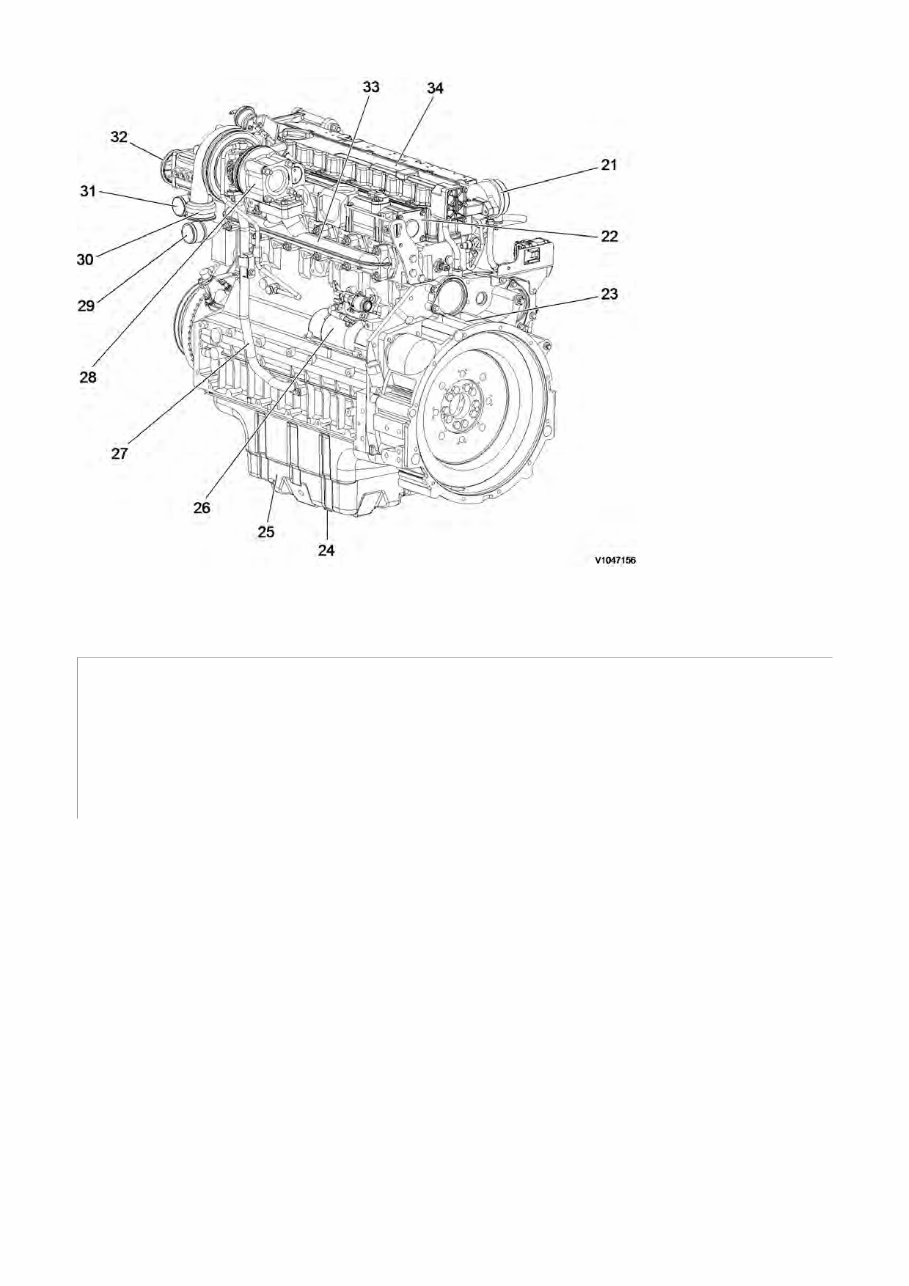
Service Information Document Title: Function Group: Information Type: Date: Component locations 200 Service Information 2014/9/11 Profile: EXC, FC2421C [GB] Component locations Component position, engine D6E. The following figures show the position of a number of components on engine D6E. Figure 1 Component locations, front side 1 Engine oil filler 11 Oil dipstick 2 Air inlet 12 Power take off 3 Transport eye 13 Engine oil filter 4 Alternator 14 Connection to E-ECU 5 Fuel feed pump 15 Fuel filter 6 V-rib belt drive on crankshaft 16 Crankcase bleeding valve 7 V-rib belt 17 High pressure fuel pump 8 Automatic belt tensioner 18 Common rail 9 Coolant pump 19 Injector 10 Engine oil cooler
Figure 2 Component locations, flywheel side 21 Crankcase bleeding valve 28 Turbocharger 22 Charge air manifold 29 Coolant inlet 23 Flywheel housing 30 Air outlet (to charge air cooler) 24 Drain plug 31 Coolant outlet 25 Oil pan 32 Air inlet (from charge air cooler) 26 Starter motor 33 Exhaust manifold 27 Oil return line from turbocharger 34 Cylinder rocker arm cover
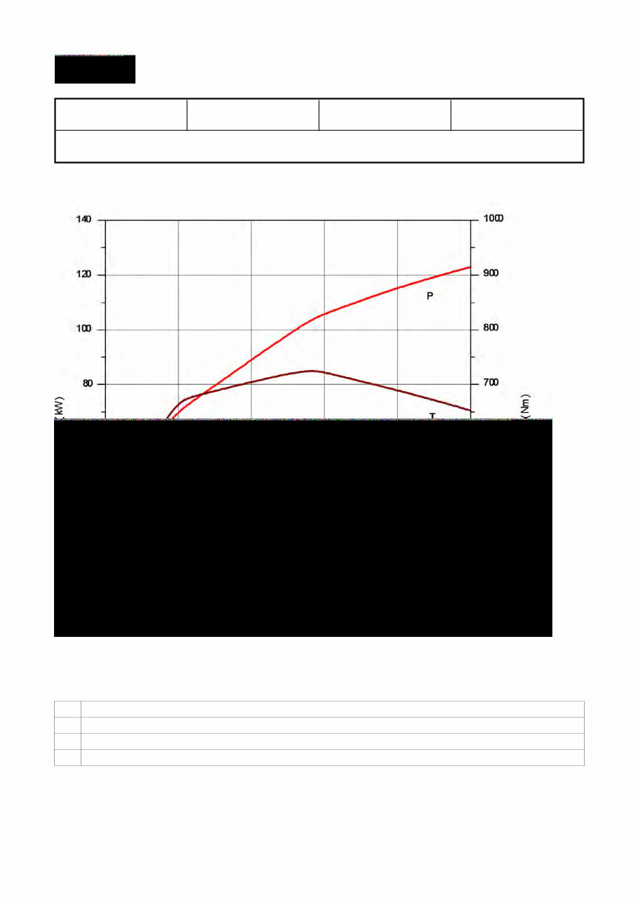
Service Information Document Title: Function Group: Information Type: Date: Engine characteristic curve 210 Service Information 2014/9/11 Profile: EXC, FC2421C [GB] Engine characteristic curve Figure 1 Engine, characteristic curve P Output power S Engine speed T Torque be Fuel consumption
Service Information Document Title: Function Group: Information Type: Date: Basic check, Engine 210 Service Information 2014/9/11 Profile: EXC, FC2421C [GB] Basic check, Engine NOTE! Certain tests and checks are performed with unlocked safety locking lever. Make sure that the machine cannot operate unexpectedly when the control lockout lever is unlocked. Purpose of the basic check The purpose of the basic check is to provide fast and accurate information about the general condition of the engine. The basic check should be performed and evaluated according to instructions in the PC-tool VCADS Pro. Tests included in the basic check The basic check which is divided into the following tests should be performed after reading out error codes and checking parameters. Tests: 1. 2. 3. Cylinder compression, test The purpose of the test is to show if any cylinder has a deviating compression pressure. The test replaces the old pressure check method but does not give any absolute values. Feed pressure, test The purpose of the test is to check that the feed pressure is as per specification. Sensor, test The purpose of the test is to check the function of all sensors.
Service Information Document Title: Function Group: Information Type: Date: Troubleshooting 210 Service Information 2014/9/11 Profile: EXC, FC2421C [GB] Troubleshooting General about troubleshooting When a malfunction is suspected or has been confirmed, it is important to identify the cause as soon as possible. The starting point for all troubleshooting is that there is some type of trouble symptom or malfunction. Malfunctions can be indicated by: generation of error codes detection of a malfunction symptom. Troubleshooting work The first step in troubleshooting is to gather information from the operator concerning the malfunction symptoms, see Electrical and information system, Collection of basic data. Then, attempt to pin-point the cause by checking in a certain order, for more information, see Electrical and information system, troubleshooting strategy. The different checking steps are: Check error codes Check parameters Perform basic check Troubleshooting information The following is included in Electrical and information system and is used when troubleshooting: 1. 2. 3. 4. 5. 6. 7. 8. 9. Troubleshooting strategy Describes troubleshooting work, step by step. Troubleshooting, assistive devices Brief summary of the assistive devices that are available for troubleshooting. Functional checks and tests, VCADS Pro Brief description of VCADS Pro. For a detailed description, see VCADS Pro User’s Manual. Error code information Contains information regarding error code design, lists of all error codes and error code information about each error code. Components, troubleshooting and specifications Contains methods and measuring values for troubleshooting of components. Also includes wiring diagrams and certain specifications. Parameters Incorrectly set parameters may cause malfunction symptoms. The parameter list includes all limit and command values for parameters. Control units, functional description Describes the functions of the control units, inputs and outputs as well as communication between the various control units. Control units, active and passive measuring Contains measuring values for active and passive measuring of the ECUs. Software functions Describes the pre-requisite conditions for the control and monitoring functions that are performed by the software in the ECUs.
Service Information Document Title: Function Group: Information Type: Date: Cylinder head, description 211 Service Information 2014/9/11 Profile: EXC, FC2421C [GB] Cylinder head, description The cylinder head is made of grey cast iron and is common for all cylinders. The induction air enters vertically (A) and the exhausts leave horizontally (B). Inlets and exhaust outlets are located on the same side of the cylinder block. Inlet and exhaust valve size is increased to optimize the gas exchange and combustion process. Valve guides are replaceable. Coolant flow in the cylinder head is modified to accommodate an outlet controlled cooling system. On order for the engine to fulfill governing emission standards, there are 3 cylinder head gaskets of different thicknesses between the cylinder head and the piston. Figure 1
Get your hands on the Volvo FC2421C Excavator Service Repair Manual for comprehensive maintenance guidance. This electronic manual offers a significant advantage over its paper counterpart, allowing you to zoom in on any part for clear visibility on your computer. It covers a wide range of topics including safety, standard parts, engine, electrical system, power transmission, brake, hydraulic system, and more. Whether you're a professional mechanic or a DIY enthusiast, this manual provides detailed step-by-step instructions to facilitate easy repairs, potentially saving you expenses.
This manual covers all serial numbers and includes hydraulic and electric schematics. It is compatible with all versions of Windows and Mac, and is available in English language. The only requirements are Adobe Reader and Win.
Recently Viewed
5,521,897Happy Clients
2,594,462eManuals
1,120,453Trusted Sellers
15Years in Business
Price:
Actual Price:
Volvo FC2421C Excavator Service Repair Manual INSTANT