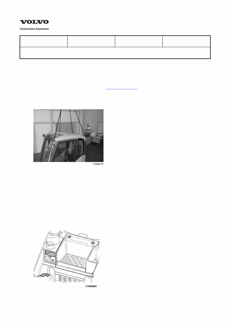
Service Information Document Title: Function Group: Information Type: Date: Cab, removing 810 Service Information 2014/4/24 Profile: EXC, EW140C, EW160C, EW180C [GB] Cab, removing Op nbr 810-001 1. Park the machine in the service position A, see 091 Service positions 2. Turn off battery disconnect switch. 3. Attach wire ropes to the lifting shackles of the cab, and raise the hoist until there is no slack in the wire ropes. Figure 1 Attaching wire lopes to the lifting hooks 1. 2. 3. 4. Shackles Lifting hooks Wire ropes Cab 4. Remove the footrest and take out floor mat. 5. Move the operator's seat to the front position and fold the backrest forward. 6. Remove the plastic casing cover over the cab fan. Figure 2 Removing plastic casing
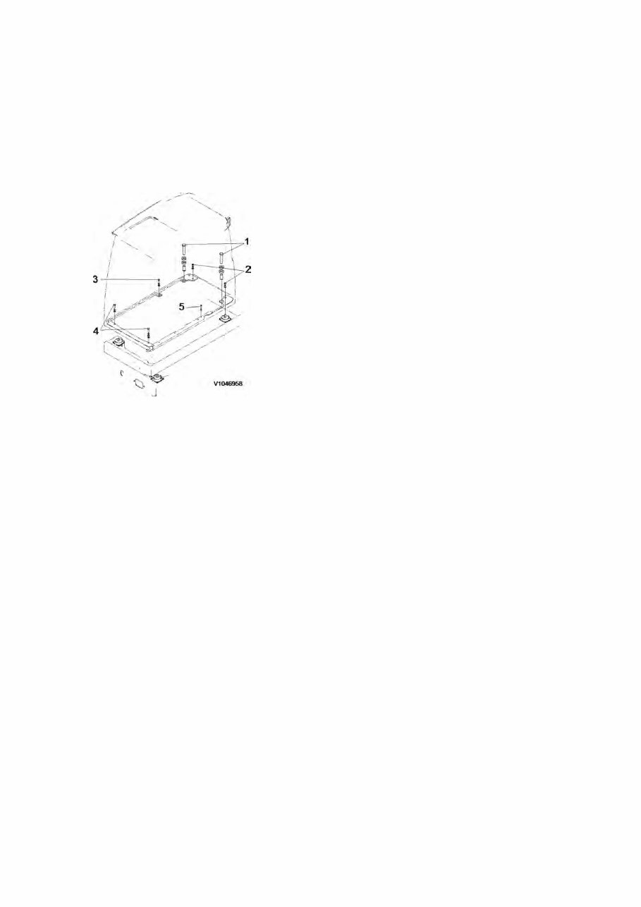
7. Disconnect main wire harness and antenna cable and washer nozzle. 8. Take out ducts and disassemble V-ECU from cab left wall and put it on the air conditioner unit. 9. Remove the mounting screws and EOPS (Excavator Operator Protective Structure) screws located at the bottom plate of the cab. The EOPS screw seal should be replaced and glued (taped) to both EOPS screw and washer when EOPS screw is removed. NOTE! Before lifting the cab, be sure to lock the door to the latch. Figure 3 Cab 1. 2. 3. 4. 5. Screws: torque ( 43.3 ± 7.2 lbf.ft), (58.8 ± 9.8 N.m), (6.0 ± 1.0 kg.m) Screws: torque ( 192.7 ± 19.4 lbf.ft), (261.1 ± 26.4 N.m), (26.7 ± 2.7 kg.m) Screws: torque ( 192.7 ± 19.4 lbf.ft), (261.1 ± 26.4 N.m), (26.7 ± 2.7 kg.m) Screws: torque ( 192.7 ± 19.4 lbf.ft), (261.1 ± 26.4 N.m), (26.7 ± 2.7 kg.m) Screws: torque ( 46.9 ± 5.0 lbf.ft), (63.7 ± 6.8 N.m), (6.5 ± 0.7kg.m) 10. Lift the cab just a little, and after confirming safety all around lift up and out. 11. Lower the cab on the ground.
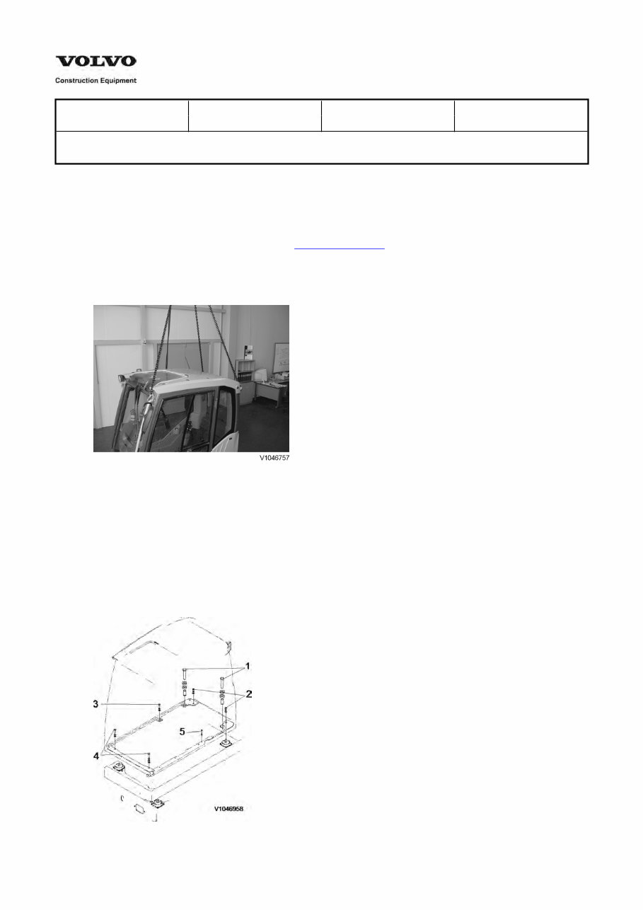
Service Information Document Title: Function Group: Information Type: Date: Cab, installing 810 Service Information 2014/4/24 Profile: EXC, EW140C, EW160C, EW180C [GB] Cab, installing Op nbr 810-002 1. Park the machine in the service position A, see 091 Service positions 2. Assemble shackles on the roof. 3. Attach wire ropes to the lifting shackles of the cab, and raise the hoist until there is no slack in the wire ropes. Figure 1 1. 2. 3. 4. Shackles Lifting hooks Wire ropes Cab 4. Lift up cab using crane and fit it to the mounting plate. 5. Tighten the screws and EOPS ( Excavator Operator Protective Structure) screws to fix the cab on the bottom plate. Figure 2
Cab 1. 2. 3. 4. 5. Screws: torque ( 43.3 ± 7.2 lbf.ft), (58.8 ± 9.8 N.m), (6.0 ± 1.0 kg.m) Screws: torque ( 192.7 ± 19.4 lbf.ft), (261.1 ± 26.4 N.m), (26.7 ± 2.7 kg.m) Screws: torque ( 192.7 ± 19.4 lbf.ft), (261.1 ± 26.4 N.m), (26.7 ± 2.7 kg.m) Screws: torque ( 192.7 ± 19.4 lbf.ft), (261.1 ± 26.4 N.m), (26.7 ± 2.7 kg.m) Screws: torque ( 46.9 ± 5.0 lbf.ft), (63.7 ± 6.8 N.m), (6.5 ± 0.7kg.m) 6. Reassemble V-ECU and 4 ducts. 7. Connect main wire harness, I-ECU wire harness and washer nozzle. 8. Install the screws of the plastic plate between fan and seat and screws of the cassette radio bracket. 9. Return the operator's seat to the original position. 10. Fit floor mat and assemble the footrest. 11. Remove shackles and roof. 12. Remove lower windscreen glass from cab door and fit it to the original place. 13. Switch on battery disconnect switch. 14. Check the machine operation and all equipment.
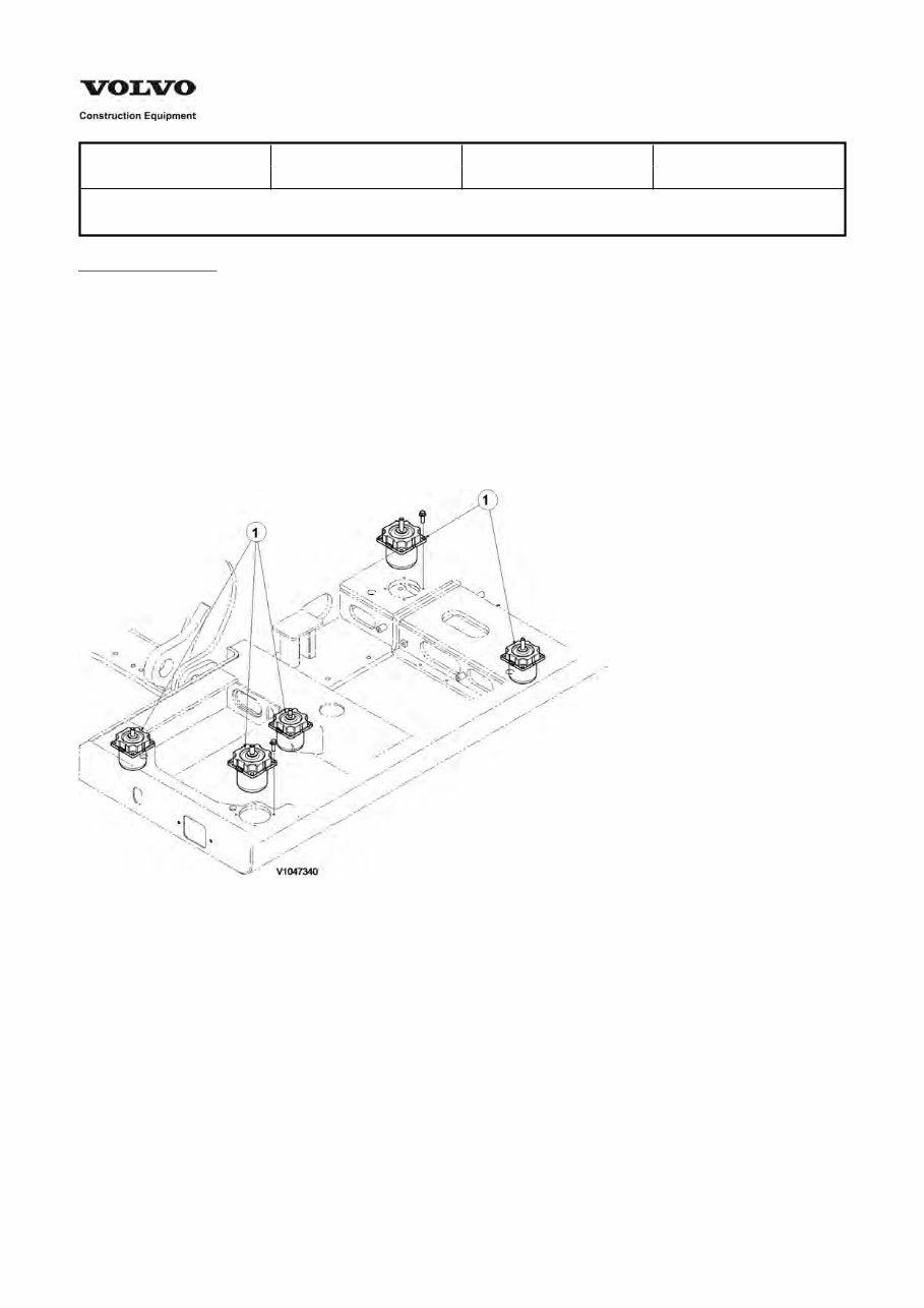
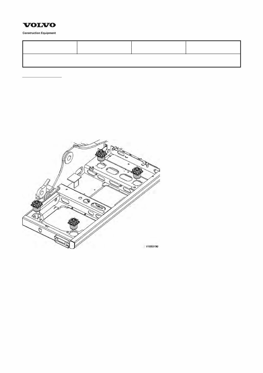
Service Information Document Title: Function Group: Information Type: Date: Cab suspension, description 818 Service Information 2014/4/24 Profile: EXC, EW160C [GB] Go back to Index Page Cab suspension, description The bottom plate of the cab is mounted on the five suspension, and then assembled to the superstructure. The cab suspension is designed to absorb vibration generated when operating the machine. Silicon oil and gas inside the suspension absorbs extreme shock impact. NOTE! If the cab suspension is dropped or impacted, silicon oil may be leaked and lower the performance. NOTE! The cab suspension exterior is natural rubber with low oil resistance. Avoid contact with grease and oil. Figure 1 Cab suspension, position 1. Screw (flange) , torque : (33.2 ±3.6 lbf.ft), (45.1 ± 4.9 N.mt) (4.6 ± 0.5 kg.m)
Service Information Document Title: Function Group: Information Type: Date: Cab suspension, description 818 Service Information 2014/4/24 Profile: EXC, EW160C [GB] Go back to Index Page Cab suspension, description The bottom plate of the cab is mounted on the four suspension, and then assembled to the superstructure. The cab suspension is designed to absorb vibration generated when operating the machine. Silicon oil and gas inside the suspension absorbs extreme shock impact. NOTE! If the cab suspension is dropped or impacted, silicon oil may be leaked and lower the performance. NOTE! The cab suspension exterior is natural rubber with low oil resistance. Avoid contact with grease and oil. Figure 1 Cab suspension, position
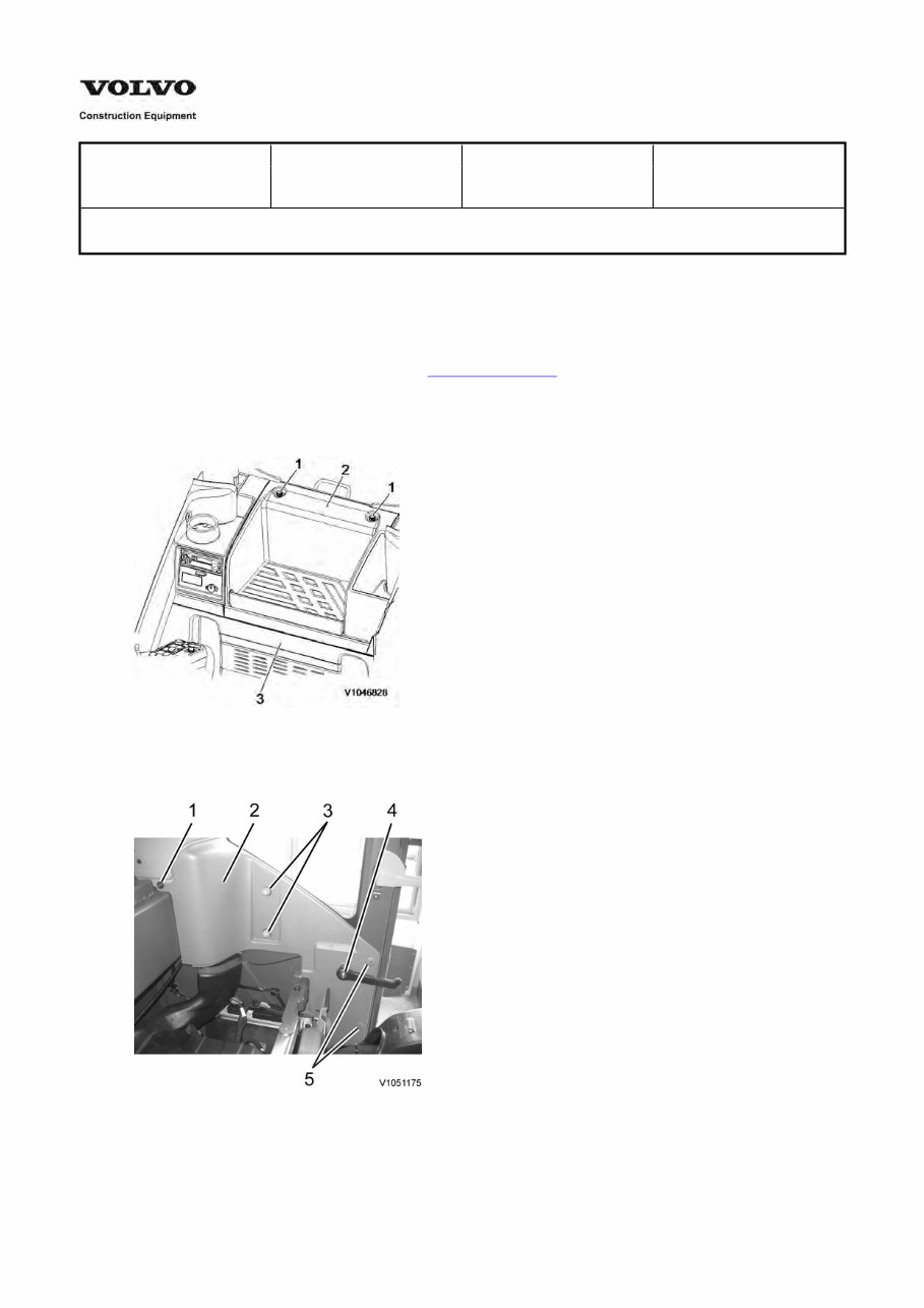
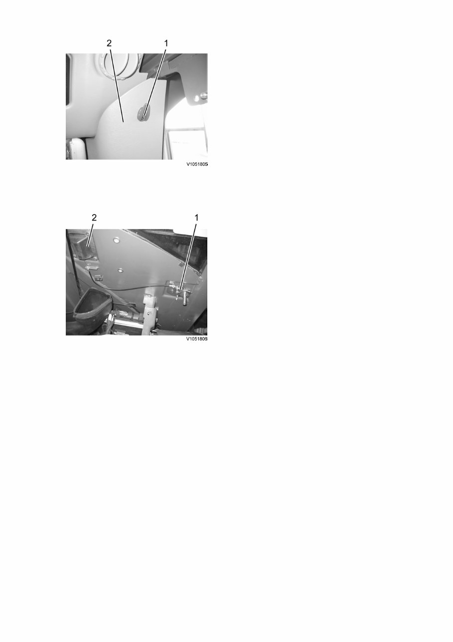
Service Information Document Title: Function Group: Information Type: Date: Cab door, removing door catch 831 Service Information 2014/4/24 Profile: EXC, EW140C, EW160C, EW180C [GB] Cab door, removing door catch Op nbr 831-052 1. Place the machine in the service position B, see . 091 Service positions 2. Move the operator's seat to the front position, and fold the backrest forward. 3. Loosen screws (1), and remove cover (2) and (3) from the cab. Figure 1 Cover, removal 4. Remove screws (1), (3), (4) and (5), and remove plastic casing (2). Figure 2 Cover, removal 5. Remove screws (1), and remove plastic casing (2).
Figure 3 Cover, removal 6. Remove door catch wire (1). Figure 4 Door catch, removal 7. Remove door catch (2) from the cab.
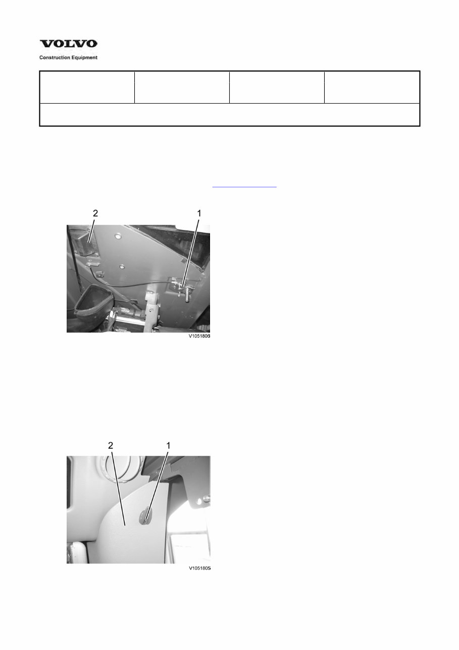
Service Information Document Title: Function Group: Information Type: Date: Cab door, installing door catch 831 Service Information 2014/4/24 Profile: EXC, EW140C, EW160C, EW180C [GB] Cab door, installing door catch Op nbr 831-053 1. Place the machine in the service position B, see . 091 Service positions 2. Install door catch wire (1). Figure 1 Door catch, installation 3. Seal around door catch (2) with sealant, and install it to the cab. 4. Install the wire to door catch (2). 5. Check the door catch operation. 6. Install cover (2), and tighten screw (1). Figure 2 Cover, installation
Get your hands on the VOLVO EW160C Excavator Service and Repair Manual, a comprehensive guide to fixing issues in your vehicle. Whether you're a professional mechanic or a DIY enthusiast, these manuals provide detailed instructions and procedures for effective repairs. The manual includes technical data, diagrams, a complete list of parts, and images, making it easy for even novice mechanics to follow along. It covers a wide range of sections and contains hundreds of photos. The manual is available in .PDF format and is not interactive. It is a valuable resource for maintaining, servicing, diagnosing, and repairing your vehicle or truck. The manual covers maintenance, engine, control system, mechanical, fuel service specifications, emission control, and much more. It is compatible with all versions of Windows and Mac, and all pages are printable. With this manual, you can save time and gain in-depth knowledge about your vehicle, allowing you to perform repairs with confidence. It's a convenient and practical resource that you can access anytime, anywhere.
Articulated haulers (ART)
5350 (Volvo BM)
5350B (Volvo BM)
5350B 4x4 (Volvo BM)
...
Backhoe loaders (BHL)
BL60 (Volvo)
BL61 (Volvo)
BL61 PLUS (Volvo)
...
Compact excavators (CEX)
EC13 XR (Volvo)
EC13 XTV (Volvo)
EC14 (Volvo)
...
Asphalt compactors (COA)
CR24 (Volvo)
CR30 (Volvo)
DD112HF (Volvo)
...
Soil compactors (COS)
SD100 C (Volvo)
SD100D (Volvo)
SD105TF (Volvo)
...
Compact wheel loaders (CWL)
L20B (Volvo)
L25B (Volvo)
L30 (Volvo BM)
...
Excavators (EXC)
EC130 (Akerman)
EC130C (Akerman)
EC130C (Volvo)
...
Motor graders (GRD)
G710 (Volvo)
G710 VHP (Volvo)
G710B (Volvo)
...
Tracked pavers (PAT)
ABG2820 (Volvo)
ABG325 (Volvo)
ABG5820 (Volvo)
...
Wheeled pavers (PAW)
ABG3870 (Volvo)
ABG4361 (Volvo)
ABG4371 (Volvo)
...
Pipelayers (PLC)
PL4608 (Volvo)
PL4611 (Volvo)
Road wideners (RWD)
RW100A (Volvo)
RW195D (Volvo)
Screed/Screeds (SCR)
10 FT EIectric WL (Volvo)
10 FT Wedgelock (Volvo)
2.5/5B HSE (Volvo)
...
Skid steer loaders (SSL)
MC110 (Volvo)
MC110B (Volvo)
MC60 (Volvo)
...
Wheel Loaders (WLO)
4200 (Volvo BM)
4200B (Volvo BM)
4300 (Volvo BM)
...
This manual is not generic and provides vehicle-specific information. It includes complete step-by-step instructions, diagrams, illustrations, wiring schematics, and specifications for easy repairs. The manual is compatible with Windows Vista 32 and 64, XP, ME, 98, NT, 2000, and Mac. It covers a wide range of topics including maintenance, engine, control system, mechanical, fuel service specifications, emission control, and more. The manual is printable, allowing you to print only the pages and diagrams you need. It is a valuable resource for both professional mechanics and DIY enthusiasts, providing detailed information to maintain and repair your vehicle or truck with ease.