Volvo ECR38 Compact Excavator Service & Repair Manual
What's Included?
Lifetime Access
Fast Download Speeds
Offline Viewing
Access Contents & Bookmarks
Full Search Facility
Print one or all pages of your manual
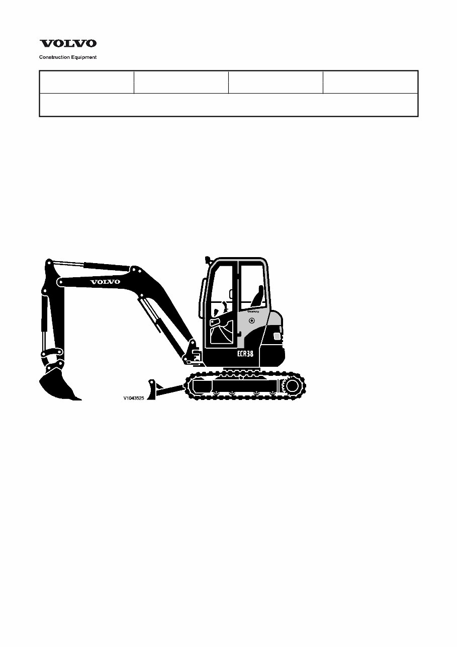
Service Information Document Title: Function Group: Information Type: Date: Description, general 000 Service Information 2014/4/7 0 Profile: CEX, ECR38 [GB] Description, general The ECR38 is a Compact excavator with caterpillar drive The engine is a water-cooled Volvo diesel engine with direct injection of the D1.6C/D1.6A type. 3-cylinder low emission engine with automatic idle shut-off. The drive movement takes place via two tracks. Each track is driven by an axial piston engine with two speeds and a planetary gear. The hydraulic system is a hydraulic load-sensing system which guarantees complete independence of the individual movements. The superstructure swivel movement is guaranteed by a hydraulic radial piston motor which directly (i.e. without reduction gear) drives a ball-mounted swing ring gear with internal toothing and remote lubrication. The undercarriage consists of a centre section in X-form to increase the torsional rigidity and chamfered side members. Figure 1 Compact Excavator ECR38
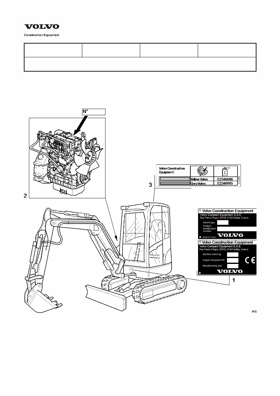
Service Information Document Title: Function Group: Information Type: Date: Product plate, description 000 Service Information 2014/4/7 0 Profile: CEX, ECR38 [GB] Product plate, description The diagrams and descriptions below show the rating plates on the compact excavator. When ordering spare parts and for telephone enquiries and in correspondence, always quote the model designation and product identification number. Figure 1 Product plates 1. 2. 3. Name plate Engine product plate Colour code 1. Name plate
2. 3. The name plate gives the manufacturer's name and address, model/type designation, product identification number, machine weight, engine power, year of production and EC symbol (in EU countries only). Engine product plate The engine product plate is on the dump lever cover. Colour code The colour code is given on a sticker on the roof of the driver's cab.
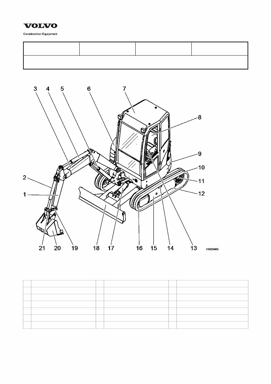
Service Information Document Title: Function Group: Information Type: Date: Location of components 030 Service Information 2014/4/7 0 Profile: CEX, ECR38 [GB] Location of components Figure 1 Location of components 1 Arm 8 Operator's seat 15 Undercarriage 2 Bucket cylinder 9 Counterweight 16 Idler 3 Boom 10 Tracks 17 Dozer blade cylinder 4 Arm cylinder 11 Track motor 18 Dozer blade 5 Boom cylinder 12 Bottom roller 19 Yoke 6 Bonnet 13 Control lever 20 Bucket 7 Cab 14 Top roller 21 Link
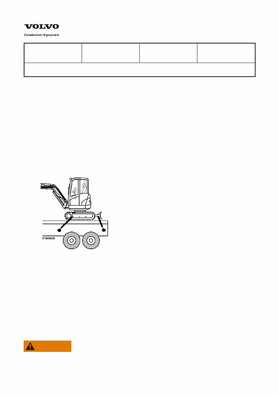
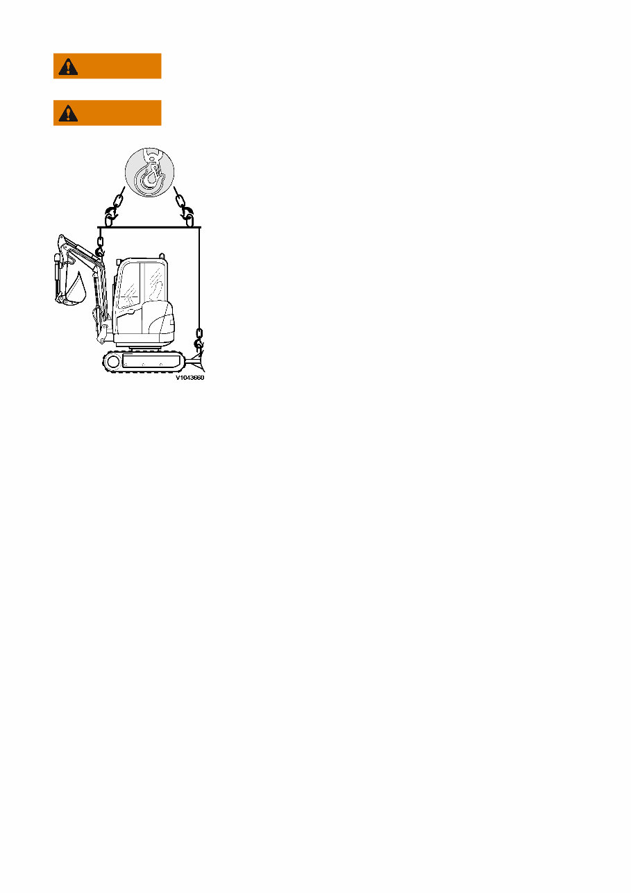
Service Information Document Title: Function Group: Information Type: Date: Transporting and lifting the machine 050 Service Information 2014/4/7 0 Profile: CEX, ECR38 [GB] Transporting and lifting the machine NOTE! On transport of the machine, the relevant regulations concerning weight, width, height, length and security of load must be observed. A suitable loading ramp must be used. To prevent slipping of the machine, mud, grease, oil etc. must be removed from the ramp and trailer. After loading, block both tracks and secure the machine with chains or straps designed for a corresponding load. Charging 1. 2. 3. Align machine tracks to the ramp with the dozer blade to the back (to serve as a safety support in the event of incorrect operation). The excavator equipment should face the front (position A). NOTE! If the dozer blade is at the rear (construction rotation through 180°), control of the direction of travel is reversed. Figure 2 Lashing Advance to the end of the ramp, extend the excavator equipment (position B), the machine tips onto the trailer loading surface. Lower excavator equipment and dozer blade onto the loading platform. Secure both tracks with wedges. Lash the machine to the loading platform of the transport vehicle using chains or straps. Unloading 1. 2. 3. Turn excavator equipment and dozer blade through 180°. Slowly advance to the start of the ramp, extend excavator equipment (position B), proceed until the machine tips in the direction of the ramp slope. Slowly drive down until the machine is on the ground again. Lifting WARNING Never lift the machine with a person in the cab.
WARNING Only use lifting devices with adequate capacity. WARNING Never lift the machine in any other way than described below. Figure 3 Lifting NOTE! Only lift the machine as shown. Incorrect lifting can lead to the load shifting, which can cause damage or injury. To lift the machine, use the lashing points provided. The location of the lashing points is shown on the picture. 1. 2. Park the machine on a firm flat surface if possible. Lift the machine with a suitable lifting tool
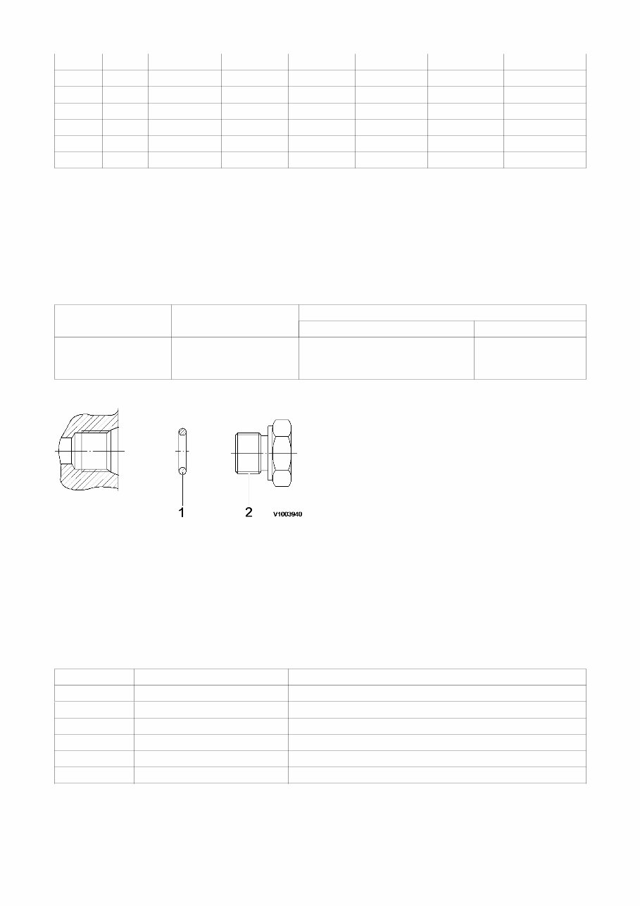
Service Information Document Title: Function Group: Information Type: Date: Hydraulic cylinders, dieseling 091 Service Information 2014/4/7 0 Profile: CEX, ECR38 [GB] Hydraulic cylinders, dieseling If air enters the hydraulic cylinders during work on the hydraulic system, this can lead to spontaneous ignition, an effect known as dieseling. This occurs if a favourable mixture of air and hydraulic oil is compressed when the piston approaches its end position in the cylinder. A sufficiently high temperature can be reached for the mixture to spontaneously ignite. NOTICE The dieseling effect may result in burnt piston seals and bushings. In order to prevent dieseling, the lines for the hydraulic cylinders must be bled after work is completed, as follows: Operate the digging equipment several times with no load and full cylinder strokes. Position the dipper arm and bucket cylinders so that any air collects at the cylinder's outlet side, that is, it should be the highest point. The piston should be at the opposite end of the cylinder. Wait approx. 1 minute from the time that the cylinder has reached its position before running the piston towards the outlet side. Repeat 3 to 5 times. The boom cylinders, which cannot be pointed downward, must be run in and out approx. 5 times without bucket load. NOTICE If the cylinders are pressurized either through lifting of the machine or lifting of a load in the bucket, without first performing the mentioned bleeding movements, the seals will likely be damaged. If a cylinder is to be pressure-tested after a repair, the piston rod should be run in and out a few times before increasing the pressure to testing pressure.
Get access to a comprehensive service and repair manual for the Volvo ECR38 Compact Excavator. This manual includes detailed procedures for service, maintenance, troubleshooting, and part replacements. It features step-by-step instructions, clear images, and exploded-view illustrations, making it valuable for both professional mechanics and DIY enthusiasts.
With manufacturer-sourced procedures and easy-to-understand instructions, this manual enables safe and efficient servicing and repair of the excavator. It contains comprehensive diagrams, detailed illustrations, and all the necessary technical information and specifications provided by the manufacturer.
Whether you're on the trail or at a jobsite, having this manual on your smartphone or laptop ensures that you have the necessary repair guidance at your fingertips. This helps in minimizing downtimes by enabling quick and effective repairs.
Printable: Yes
Language: English
Compatibility: Compatible with various electronic devices including PC, Mac computers, Android and Apple smartphones, and tablets.
Requirements: Adobe Reader (free)
Recently Viewed
5,521,897Happy Clients
2,594,462eManuals
1,120,453Trusted Sellers
15Years in Business
Price:
Actual Price:
Volvo ECR38 Compact Excavator Service & Repair Manual