

Volvo EC35 Compact Excavator Full Service & Repair Manual
What's Included?
Fast Download Speeds
Offline Viewing
Access Contents & Bookmarks
Full Search Facility
Print one or all pages of your manual
Service Information
Document Title: Function Group: Information Type: Date:
Position of components 000 Service Information 2014/4/16
Profile:
CEX, EC35 [GB]
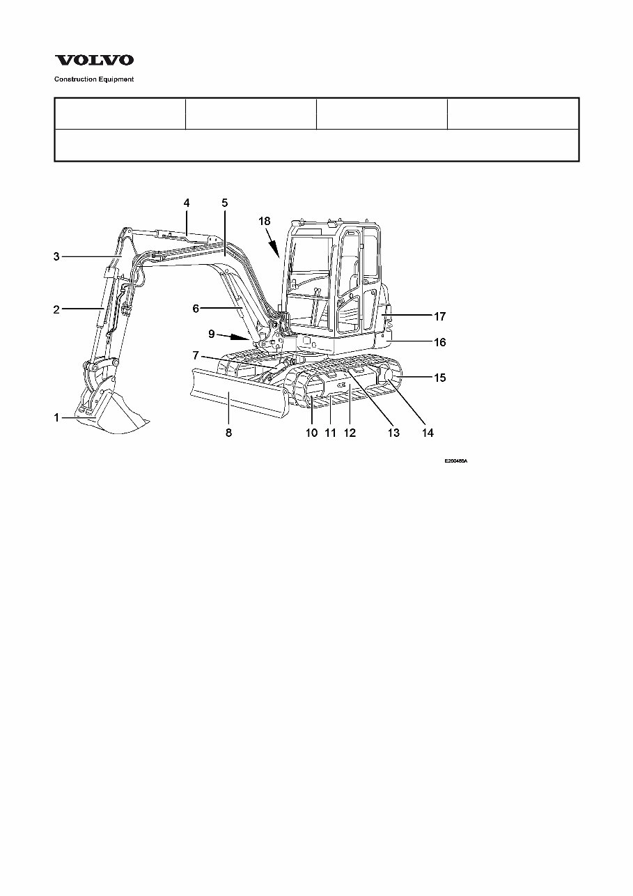
Position of components
Figure 1
Position of components
1 Bucket 10 Tensioning wheel
2 Bucket cylinder 11 Rollers
3 Dipper, standard version 12 Main chassis
4 Dipper cylinder 13 Top roller
5 Boom 14 Track sprockets/travel gear motors
6 Boom cylinder 15 Tracks
7 Dozer blade cylinder 16 Slewing superstructure
8 Dozer blade 17 Engine cover
9 Boom offset cylinder 18 Hydraulic compartment cover

Service Information
Document Title: Function Group: Information Type: Date:
Load capacity tables EC 45 030 Service Information 2014/4/16
Profile:
CEX, EC35 [GB]
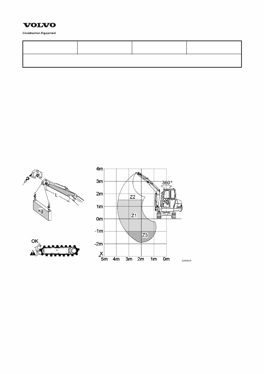
Load capacity tables EC 45
Rated handling loads in kg, i.e. 75% of the tipping load or 87% of the hydraulic limit. (* = hydraulic limit)
These loads apply for the complete height concerned (Z.), for the specified reach. Increase by 3% for steel tracks,
except the values marked with * (hydraulic limits).
The specified values are valid for a machine:
without attachment and without quick coupling.
If handling is accomplished in lifting gear operation with an assembled tool and/or assembled standard connecting
system, the weight of these attachments must be subtracted from the values stated in the table.
On level, compact ground.
With full rotation of the superstructure.
On rubber tracks.
Equipment parallel to the axis of the superstructure.
With a 75 kg driver in the cab.
Figure 1
Service Information
Document Title: Function Group: Information Type: Date:
Load capacity tables EC 35 030 Service Information 2014/4/16
Profile:
CEX, EC35 [GB]
Load capacity tables EC 35
Rated handling loads in kg, i.e. 75% of the tipping load or 87% of the hydraulic limit. (* = hydraulic limit)
These loads apply for the complete height concerned (Z.), for the specified reach. Increase by 3% for steel tracks,
except the values marked with * (hydraulic limits).
The specified values are valid for a machine:
without attachment and without quick coupling.
If handling is accomplished in lifting gear operation with an assembled tool and/or assembled standard connecting
system, the weight of these attachments must be subtracted from the values stated in the table.
On level, compact ground.
With full rotation of the superstructure.
On rubber tracks.
Equipment parallel to the axis of the superstructure.
With a 75 kg driver in the cab.
Figure 1

Service Information
Document Title: Function Group: Information Type: Date:
VOLVO standard tightening
torques
030 Service Information 2014/4/16
Profile:
CEX, EC35 [GB]
VOLVO standard tightening torques
The tightening torques in the following tables apply for screw connections of the corresponding strength class.
If not specified differently, the tables are to be considered as general instructions for the tightening of screw connections.
NOTE!
For flange bolts of type U6FS the values must be increased by 10%. Screws and nuts must be clean and oiled.

file:///C|/Users/yeqiwen/Documents/可牛闪图/QIWEN-YE-END.txt[2014/4/16 20:19:24]
Many thanks for your purchase.
Happy every day.
You're Reading a Preview
What's Included?
Fast Download Speeds
Offline Viewing
Access Contents & Bookmarks
Full Search Facility
Print one or all pages of your manual
$39.99
Viewed 16 Times Today


Secure transaction
What's Included?
Fast Download Speeds
Offline Viewing
Access Contents & Bookmarks
Full Search Facility
Print one or all pages of your manual
$39.99
- This is a comprehensive factory service repair workshop manual for the Volvo EC35 Compact Excavator.
- It covers all repairs, servicing, and troubleshooting procedures with detailed photos and diagrams.
- Professional mechanics and technicians use this manual, which includes step-by-step instructions and highly detailed exploded diagrams and pictures.
- You can print out a single page or the entire manual as per your preference.
- This manual can be used on multiple computers without any limitations or trial periods.
- There is no expiry date, renewal fee, or need to pay extra for continued use.
- It is fully compatible with Windows and MAC computers.
For instant access to this manual, please click the button below.


