Volvo EC25 Compact Excavator Full Service & Repair Manual
What's Included?
Lifetime Access
Fast Download Speeds
Offline Viewing
Access Contents & Bookmarks
Full Search Facility
Print one or all pages of your manual
Service Information Document Title: Function Group: Information Type: Date: Adjusting the pressure and checking for leaks 900 Service Information 2014/4/17 Profile: Adjusting the pressure and checking for leaks WARNING Work on the equipment or in the area of hydraulic components must only be performed by persons who have sufficient knowledge and experience in handling hydraulic systems. The following safety rules must generally be observed when working on the hydraulic system of the machine. 1. 2. 3. 4. 5. 6. 7. 8. 9. 10. Depressurize all system sections and pressure lines to be removed before starting repair work. Observe all specific notes applicable for the respective unit. Make sure that nobody can operate the machine as long as work is being performed on the machine. Avoid contact with hot and/or pressurized hydraulic oil. Always close access doors to service points before pressurizing the system in order to protect persons from hydraulic oil jets, which may be dangerous even under considerably low pressures. Use pressure gauges with long test hoses so that the pressure can be read at a safe distance. Make sure that these measuring hoses are not pinched in doors. The first lever or pedal movement should be performed slowly to prevent sudden or unexpected machine movements and pressures in excess of the specified pressures. Interrupt the pressure increase when the machine has reached the specified pressure. Do not try to exceed the specified limit value. When using adjustment devices with unknown sensitivity adjust the pressure in small increments. This is of special importance for the auxiliary hydraulic circuit in which the pressure builds up immediately when starting the engine. It has happened that the pressure increased to such a level, that the pressure gauge turned around a second time. The pressure was thereby wrongly read as being too low. It was increased further and finally caused the system to burst. Check all lines, pipes and screwed connections regularly for external leaks and damage. Repair any damage immediately. Splashed oil may cause injury. Watch out for oil leaks. Oil on the inside of a door may be a sign for an oil leak occurring during pressure build up. Use a piece of paper or cardboard (not your hands!) to check for possible leak oil losses. Check the pressure testing equipment at regular intervals and replace defective parts. Make sure that no connections are mixed up by mistake. Connections, length and quality of hoses must comply with the technical requirements.
Service Information Document Title: Function Group: Information Type: Date: General notes to be observe when working on the hydraulic system 900 Service Information 2014/4/17 Profile: General notes to be observe when working on the hydraulic system The operating safety, productivity and lifetime of a machine depends mainly on the proper use and regular maintenance of the machine. To ensure an optimal performance of the machine all information and instructions concerning the type and frequency of maintenance activities and lubrication mentioned in this instruction manual must be strictly observed and applied. Claims covered by warranty can only be accepted if all specified inspections have been performed according to schedule and by trained specialists. It is highly recommended to use only genuine spare parts, which are available from authorized VOLVO dealers. Repairs and adjustments must only be performed by qualified and trained mechanics from these authorized dealers or VOLVO sales subsidiaries. The machine described in these instructions complies with the technical regulations valid at the date of issue. We reserve the right to implement any changes or modifications to machine components deemed useful or necessary at any time without prior notification. This does not include the obligation to change the content of this manual accordingly. Illustrations and information contained in this manual are not binding and cannot be subject of any claims. Safety guidelines to be observed during service and repair work The engine must be shut down and the working attachment lowered to the ground or supported. The pressure relief and safety valves in the hydraulic circuits of excavators may only be adjusted by VOLVO service personnel. Any changes to their adjustment will render the warranty null and void. The service manual must always be close at hand when performing repair work. Beside the repair instructions all applicable legal regulations concerning the avoidance of accidents and the protection of the environment must also be observed. Before starting work on the machine all service personnel involved in such repairs must have read this manual and should be acquainted with the operation of the machine and the different control functions. Before starting work all persons involved must have read the repair instructions and especially the chapter on safety. These notes must not be read while already performing this work. This applies especially for persons who are only occasionally involved in repairs on this machine. These notes also deal with the handling of hazardous substances, the protective outfit of the personnel and the traffic regulations. From time to time the workshop manager must check whether the personnel is sufficiently trained and performs all work in compliance with the repair instructions and is aware of the safety risks. Work on and with the machine must only be performed by sufficiently trained persons. Statutory minimum age limits must be strictly observed. For safety reasons long hair must be tied back or otherwise secured. Clothes should be of tight fit. Jewellery that may be caught by the machine and cause injury must be taken off. Wear special protective outfit if required by special circumstances or by legal regulations. Observe all safety and warning notes on the machine. Make sure that all safety and warning signs are well legible at all times. Do not make any modifications, additions or changes, which might affect the safety, without the written consent of the manufacturer. This also applies for the insulation and adjustment of safety devices and pressure limitation valves as well as for welding work on load bearing elements. Replace the hydraulic hoses in the specified or convenient intervals, even if no safety affecting fault was found. Perform inspections and maintenance work in the time intervals specified in the repair instructions. Maintenance and repair work must only be carried out with suitable tools and requires appropriate workshop facilities. The personnel must be informed about the location of fire fighting equipment and the respective operating instructions. In
case of a fire apply the correct warning and fire fighting methods. When refuelling shut the engine down, do not smoke and avoid open fire. Do not use the machine in an explosive environment. Work in such area can cause fire or explosion and result in severe injury. Persons attending a training course may only work with the machine if they are permanently supervised by an experienced person. Work on the equipment or in the area of hydraulic components must only be performed by persons who have sufficient knowledge and experience in handling hydraulic systems. Persons under the influence of alcohol or drugs, which affect the responsiveness, are NOT permitted to work on the machine. Avoid any risky working methods. Run combustion engines only adequately ventilated rooms. Ensure sufficient ventilation before starting the machine inside a closed room. Start the machine only from the driver’s seat. Before starting or moving the machine make sure that there are no persons inside the movement radius of the machine. Before starting the machine you should generally make sure that all accessories are securely fastened. Always keep your hands on the control levers while the machine is in motion. If the machine has been shut down for repair or maintenance purposes preventive measures must be applied to avoid accidental starting. For this purpose lock all control elements and pull off the ignition key or attach a warning sign to the ignition switch. Perform repair and maintenance work only when the machine is parked on level ground of sufficient load bearing capacity and all necessary measures have been applied to rule out tipping over or accidental starting of the machine. In order to rule out accidents, large components or assembles, which must be removed to be replaced, must be carefully fastened and located with lifting tackle. Use only suitable and technically perfect lifting gear and lifting tackle of sufficient load bearing capacity. Do not stand under loads being lifted. Before performing maintenance and repair work remove all oil, fuel and dirt from the machine. This applies particularly for joints and connecting threads. Do not use any aggressive cleaning agents. Use only lint-free cloths. Before cleaning the machine with water, a steam jet (high pressure cleaner) or with a cleansing agent cover all openings which should normally be protected against water, steam and cleansing agents for reasons of safety or correct function. After cleaning check all fuel, lubrication oil and pressure fluid lines for leaks, loose connections, scratches and damage. Any defects found must be rectified immediately. Tighten all bolted connections which were loosened for maintenance and repair work. All safety devices removed for adjustment, maintenance or repair must be installed and checked again immediately after the work is completed. Make sure that all consumables and replaced parts are disposed of environmentally. Comply with the construction site regulations. Welding, torch cutting and grinding operations on the machine must only be performed if this has been expressly authorized, as there may be a risk of explosion or fire. Before performing welding, torch cutting and grinding operations clean the machine and its surrounding area to remove dust and inflammable substances. Ensure sufficient ventilation of the rooms (danger of explosion).
Service Information Document Title: Function Group: Information Type: Date: Test and adjustment mark for EC 25 900 Service Information 2014/4/17 Profile: Test and adjustment mark for EC 25 Date: 25.06.2001 Type EC25 Measurement Conditions Unit Engine Minimum speed rpm 900+100 Full speed rpm 2400+20 Hydraulic circuit To measure and adjust the pressure or power accelerate the engine to maximum speed. Hydraulic oil temperature: 40º - 50ºC. P1 End position of dozer blade bar 170+5 P2 End position of dipper / arm bar 230+5 P3 End position of boom bar 230+5 Auxiliary pressure / pilot pressure End position of dozer blade bar 35 ± 3 POWER CONTROL First point Auxiliary unit Q l/min 40 P bar 135 ± 10 Second point Auxiliary unit Q l/min 30 P bar 175 ± 10 For information : Length of setscrew + height of counter nut = 13 mm Load of diesel engine During the adjustment of the power control the engine speed must be higher than rpm > 2100 Now activate the end position of auxiliary unit and dozer blade. The engine speed must be higher than rpm > 2100 Q Auxiliary unit P2 = P3 = 40 bar l/min 46 ± 2 Check whether the control element with spool works correctly Boom: First use only the large section of the boom, then use the large section of the boom together with the small section of the dipper In the 2nd case the speed of the boom rod must drop Boom: First use only the small section of the doípper, then use the small section of the dipper together with the large section of the boom In the 2nd case the speed of the dipper rod must drop SLEWING GEAR Delta P (left/right, right/left) Block the slewing gear bar 155 ± 5 SPEEDS AND FLOW CAPACITIES Speed of small dipper section sec. 2 ± 0.2 Speed of small bucket section sec. 2.1 ± 0.2 Slewing speed rpm (sec./rev.) 10.5 ± 0.3 (5.7 ± 0.2) Low speed of travel motors sec./10 rev. 21
High speed of travel motors sec./10 rev. 12.6
Service Information Document Title: Function Group: Information Type: Date: Hydraulic circuit 910 Service Information 2014/4/17 Profile: Hydraulic circuit This chapter contains descriptions of the functions of the components in the hydraulic circuit and, where necessary, information on the control and adjustment of these components. The hydraulic circuit of the machine is divided into two sub-circuits, the working hydraulics and the hydraulic auxiliary or pilot circuit. The circuit for the working hydraulics consists of the working pumps for the machine, the hydraulic cylinders, the travel motors and the slewing gear motor. However, the hydraulic travel motors and the slewing motor are described in chapter 4, in order to maintain a division into standard function groups. The pressure in the circuit of the working hydraulics changes with the resistance opposed to the movements. The operating pressure is limited by pressure relief valves and the pressure peaks in the circuit are compensated by secondary pressure relief valves. Among others, the auxiliary hydraulic circuit is used to control the elements in the valve blocks, which supply the cylinder and the hydraulic slewing motor with oil. This auxiliary pressure is monitored by a pressure reducing valve. Before conduction any tests or adjustments in the hydraulic circuit for the working attachment the following precautions must be applied after the engine has been shut down: Lower the working attachment to the ground: Set the starting contactor to ON. Lower the console (seat armrest) to unlock the controls. Lower the working attachment to the ground using the boom control lever. If thze starting contactor is defective or an electrical faults occur: Remove the tool compartment. Press the button of the hydraulic safety solenoid valve and hold the button depressed. Lower the working attachment to the ground using the boom control lever. If hoses on the boom cylinder have cracked on machines with safety valve: loosen the connection of the sensor on the cylinder by 3/4 to 1 turn and lower the working attachment slowly to the ground. Retighten the connection when the process is finished. Relieving remaining pressures: Set the starting contactor to ON. Lower the console (seat armrest) to unlock the controls. Move the control lever to all directions. Disconnect the battery.
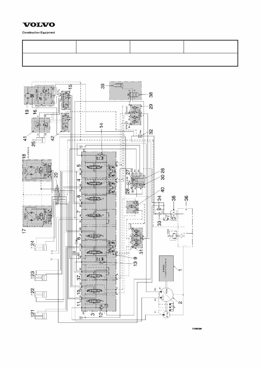
Service Information Document Title: Function Group: Information Type: Date: Hydraulic diagram 910 Service Information 2014/4/17 Profile: Hydraulic diagram Figure 1
Hydraulic diagram 1. 2. 3. 4. 5. 6. 7. 8. 9. 10. 11. 12. 13. 14. 15. 16. 17. 18. 19. 20. 21. 22. 23. 24. 25. 26. 27. 28. 29. 30. 31. 32. 33. 34. 35. 36. 37. 38. 39. 40. 41. 42. Diesel engine Hydraulic pumps (P1, P2, P3) Control valve block Bucket element Boom element Element for left hand travel motor Options element Element for right hand travel motor Dipper element Element for slewing / offset gear Dozer blade element Pressure relief valve P1 Pressure relief valve P2 Pressure relief valve P3 Solenoid valve for slewing / offset gear Crossover - valve Hydraulic travel motor, left Hydraulic travel motor, right Hydraulic slewing motor with brake Rotary oil distributor Dipper arm cylinder Bucket cylinder Boom cylinder Dozer blade cylinder Offsetting cylinder Hydraulic servo valve block (pilot pressure) Pressure reducer Auxiliary or pilot pressure accumulator Hydraulic safety solenoid valve Solenoid valve high / low speed Control lever / hydraulic control element Check valve Oil cooler By-pass valve Filter Tank Boom / dipper element (accumulated) Solenoid valve for quick tool change system Cylinder quick tool change system Slewing brake valve Balancing valve for offset cylinder Electric valve
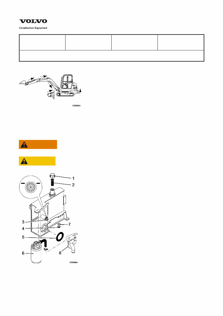
Service Information Document Title: Function Group: Information Type: Date: Changing the hydraulic oil 9111 Service Information 2014/4/17 Profile: Changing the hydraulic oil Figure 1 Operate all piston rods until they are fully retracted. Lower the working attachment to the ground and shut the engine down. WARNING Hydraulic oil may be very hot, do not touch. Danger of scalding! CAUTION Hydraulic oil must be drained off warm. Figure 2 Remove and clean the breather (1). Take out the filler screen (2), clean thoroughly and put back in.
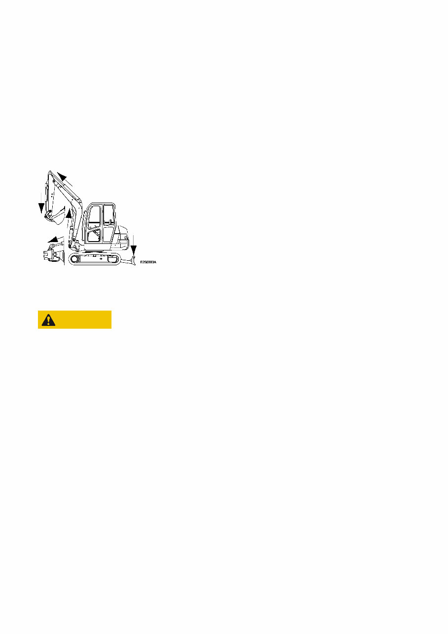
Unscrew the drain plug (4) and let all hydraulic oil run out. Take off cover (8) and gasket (5). NOTE! Check the tank for dirt deposits, clean if necessary. Install cover (8) with an new gasket (5). Assemble drain plug (4) with a new seal ring (7) and tighten with 39 ± 5 Nm. Fill the hydraulic oil tank with oil, see chapter 0 – fuels, lubricants and filling capacities – until the maximum filling level (3) is reached. Check the oil filling level (3). Assemble the breather (1). Start the engine, move the working attachment control lever slowly to both directions and perform all working movements. Figure 3 CAUTION Bleed all cylinders by extending and retracting them slowly several times in unloaded condition to avoid knocking noises in the cylinders. Check the hydraulic oil level. Extend all cylinders to their end positions ( [Invalid linktarget] ), while the machine is standing on level ground. The oil level must now comply with the level shown in [Invalid linktarget] /3. Top up oil if necessary.
Get the complete factory service repair workshop manual for the Volvo EC25 Compact Excavator. This professional manual is available for instant access on your computer, tablet, or smartphone. It covers all repairs, servicing, and troubleshooting procedures with detailed photos, diagrams, and step-by-step instructions. It is the same type of manual used by professional mechanics and technicians.
With this manual, you can print out a single page or the entire manual as per your preference. It can be used on multiple computers without any limitations or trial periods. There is no expiry date, renewal fee, or additional charges. The manual is fully compatible with Windows and MAC computers.
Whether you are a professional mechanic or a DIY enthusiast, this manual provides the necessary guidance to complete every job correctly. Click the button to get your manual now.
Recently Viewed
5,521,897Happy Clients
2,594,462eManuals
1,120,453Trusted Sellers
15Years in Business
Price:
Actual Price:
Volvo EC25 Compact Excavator Full Service & Repair Manual