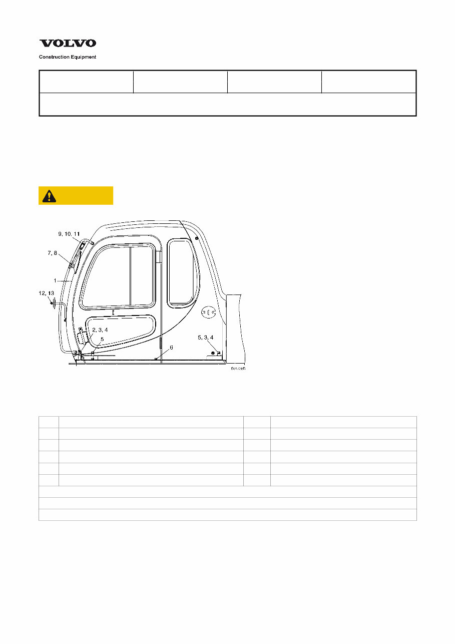
Service Information Document Title: Function Group: Information Type: Date: Cab, installation 810 Service Information 2014/6/10 Profile: Cab, installation Attach wire ropes to the lifting hooks of the cab, and lower the cab to the mounting position. Tighten the 7 mounting screws (2, 5, 6). Connect the main wiring connectors. CAUTION Take care that the cab frame does not hit the control board when removing or installing the cab. Figure 1 Cab 1 Cab 7 Mirror support 2 Screw 8 Rear view mirror 3 Plain washer 9 Screw 4 Spring washer 10 Plain washer 5 Screw 11 Spring washer 6 Screw Tightening torque : – 2, 5, 6 screw : 20 ± 2 kgf·m (144 ± 14 lbf·ft) – 9 screw : 0.8 ± 0.1 kgf·m (5.8 ± 0.7 lbf·ft)
Service Information Document Title: Function Group: Information Type: Date: Cab, removal 810 Service Information 2014/6/10 Profile: Cab, removal Attach wire ropes to the lifting hooks of the cab, and lift the cab until there is no slack in the wire ropes. Remove the 7 mounting screws (2, 5, 6) located at the bottom plate of the cab. Disconnect the main wiring connectors, air duct and storage box. Lift the cab just a little, and after confirming safety all around, lift up and out. NOTE! Cab weight : about 275 kg (605 lbs)
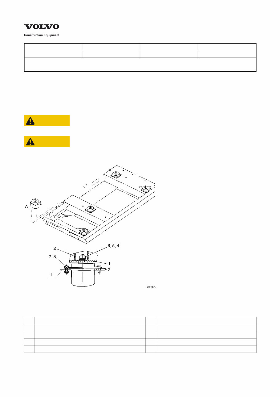
Service Information Document Title: Function Group: Information Type: Date: Viscose mount, description 810 Service Information 2014/6/10 Profile: Viscose mount, description The bottom plate where cab is assembled is mounted on 5 viscose mounts, and then assembled to the upper deck. Viscose mounts is designed to absorb vibration generated when operating the machine. Silicon oil and gas inside the viscose mounts absorbs extreme shock impact. CAUTION If the viscose mount is dropped or impacted, silicon oil may leaked and lower the performance. CAUTION The exterior of viscose mount is natural rubber with low oil resistance. Avoid contact with grease and oil. Installation position Figure 1 Installation position 1 Bottom plate 6 Nut 2 Floor mat 7 Spring washer 3 Viscose mount 8 Screw 4 Plain washer A Viscose mount 5 Spring washer U Upper deck
Service Information Document Title: Function Group: Information Type: Date: Viscose mount, installation 810 Service Information 2014/6/10 Profile: Viscose mount, installation 1. 2. 3. 4. Install the viscose mount on upper deck by tightening screw (8). Tightening torque : 6.5 ± 0.7 kgf·m (47 ± 5 lbf·ft) Check for deformation and debris on mounting surface. CAUTION The difference of height for viscose mount installed (5pcs) must be within 1mm. Tighten the lock nut (6) with specified torque. Tightening torque : 26.7 ± 2.7 kgf·m (193 ± 19 lbf·ft) Cover the floor mat. NOTE! If the ambient temperature is less than 0°C, the viscosity of silicon oil inside the viscose mount is high, and the ride is some what rough. After operating a few minutes, the viscosity will be lowered by heating due to vibration and the ride will be much smoother.
Service Information Document Title: Function Group: Information Type: Date: Viscose mount, removal 810 Service Information 2014/6/10 Profile: Viscose mount, removal 1. 2. 3. Remove the cab. Remove floor mat (2), and remove the bottom plate by loosening nut (6) tightened to bottom plate (1). Remove the viscose mount by loosening screw tightened to upper deck.
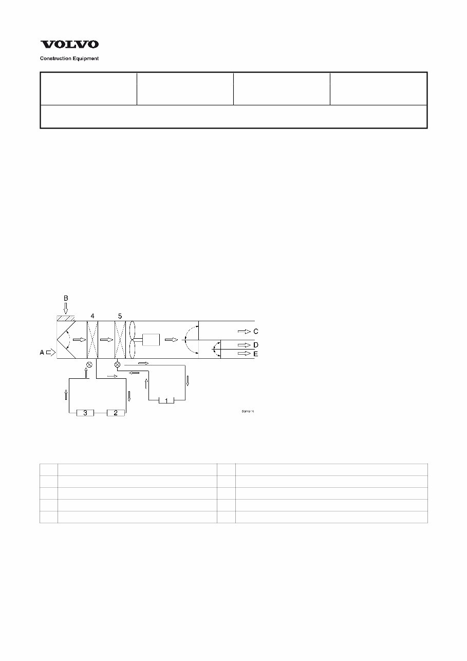
Service Information Document Title: Function Group: Information Type: Date: Air conditioning unit, description 870 Service Information 2014/6/10 Profile: Air conditioning unit, description The advanced integrated air conditioning system with the heating and the cooling system installed in a single unit is designed to provide a comfortable indoor environment in all seasons. The integrated system is ergonomically designed for the most efficient air flow distribution. The easy to use control panel provides a selection of cooling/heating and indoor/outdoor air through 8 levels and 4 fan speeds. Characteristics of an integrated air conditioning system This system provides a comfortable indoor environment with powerful cooling and heating capacity in all weather conditions. The thermistor installed in the integrated air conditioner protects the evaporator and cooling system from freezing. The cooling and heating system can be operated simultaneously to control humidity and indoor temperature. According to the indoor and outdoor air condition, indoor or outdoor air circulation can be selected. All fresh air is drawn through the air filter installed between the duct and the cab vent. Structure of integrated air conditioning system Figure 1 Structure, air conditioning system 1 Engine A Indoor air 2 Compressor B Outdoor air 3 Condenser C Face 4 Evaporator D Foot 5 Heater core E Defroster
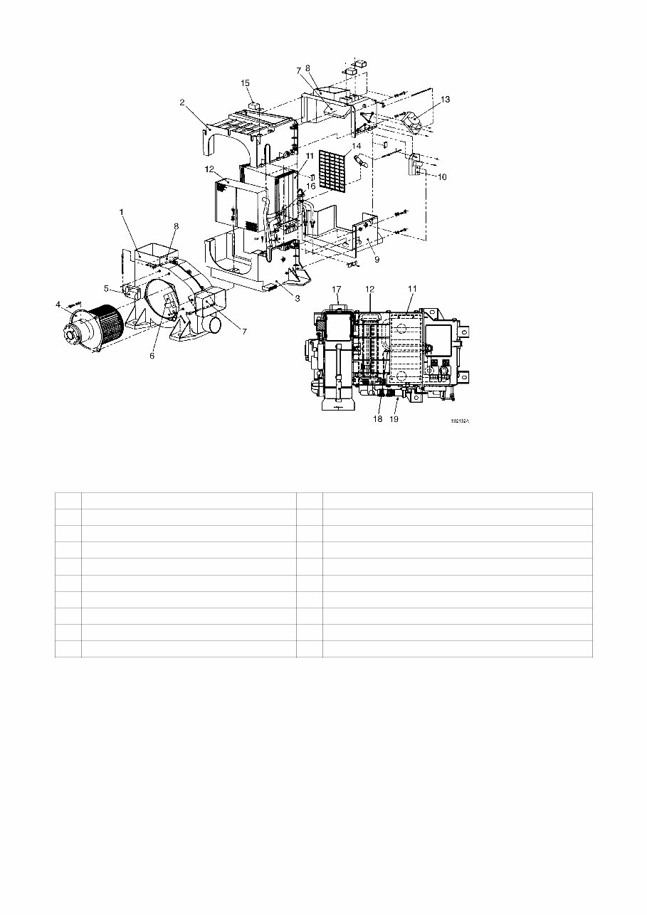
Figure 2 Number of parts, air conditioning system Quantity No. Items A C H 1 Compressor 1 1 2 Receiver dryer & condenser 1 1 Air conditioner & heater 1 3 Air conditioner 1 Heater 1 4 Supply hose A 1 1 5 Supply pipe B 1 1 6 Supply hose C 1 1 7 Hose 1 1 8 Inlet hose A 1 1 9 Inlet pipe B 1 1 10 Inlet hose C 1 1 11 Belt tensioner 1 1 12 V–belt 1 1 13 Compressor bracket 1 1 14 O–ring 2 2 15 Drain hose 2 2 16 O–ring 4 4 17 O–ring 4 4 A : Air conditioner and heater mounted C : Only air conditioner mounted H : Only heater mounted Body structure
Figure 3 Structure, air conditioning unit body 1 Blower case 11 Evaporator 2 Evaporator case-upper 12 Heater 3 Evaporator case-lower 13 Indoor / Outdoor selection motor 4 Blower motor and fan 14 Indoor filter 5 Air flow control motor 15 Relay 6 Air direction control motor 16 Heater valve 7 Shutter 17 Power transistor 8 Inlet case-upper 18 Temperature sensor 9 Inlet case-lower 19 Heater valve assembly 10 Heater valve motor
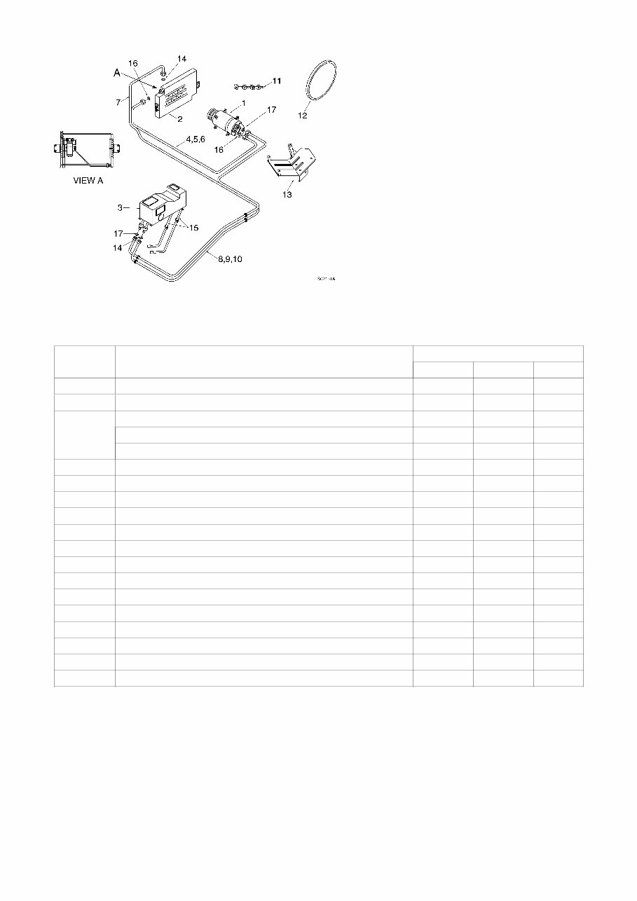
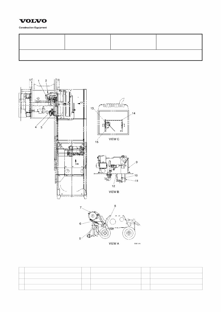
Service Information Document Title: Function Group: Information Type: Date: Air conditioning unit, related components 870 Service Information 2014/6/10 Profile: Air conditioning unit, related components Location of components Figure 1 Location of components 1 Charging hose 6 Belt tensioner 11 Inlet hose 2 Inlet hose 7 Compressor 12 Drain hose 3 Heater valve 8 V–belt 13 Charging hose 4 Heater valve 9 Body 14 Condenser
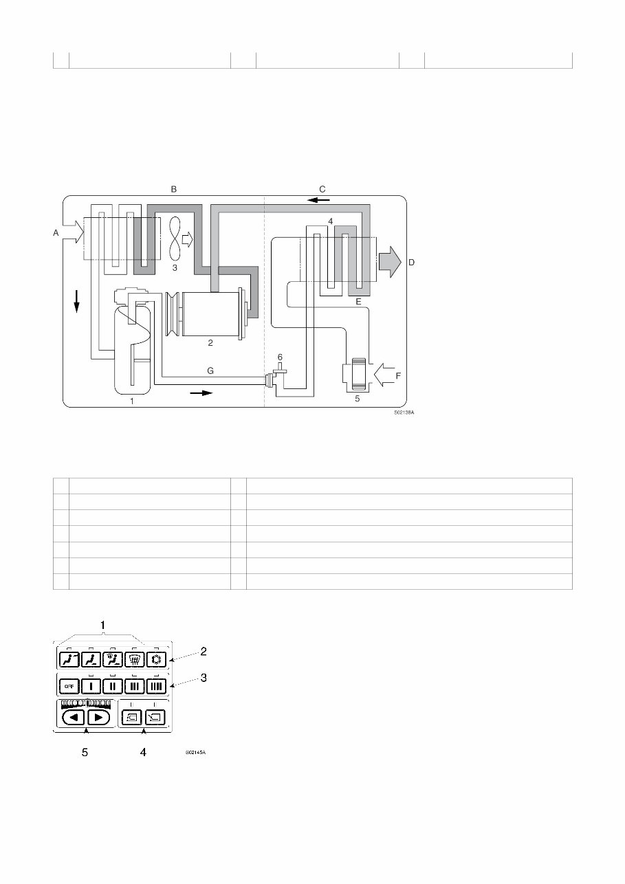
5 Compressor bracket 10 Refrigerant hose 15 Receiver dryer Tightening torque : Refrigerant hose : 1.5 ~1.8 kgf·m (11~13 lbf·ft) Charging hose : 2.0~2.5 kgf·m (14~18 lbf·ft) Inlet hose : 3.0~3.5 kgf·m (22~25 lbf·ft) Heater hose : clamp 2.5~3.0 kgf·m (18~22 lbf·ft) Refrigerant circuit Figure 2 Circuit, refrigerant 1 Receiver dryer A Outside air 2 Compressor B High temperture and high pressure gas 3 Condenser C Low temperture and low pressure gas 4 Evaporator D Cool air 5 Blower E Low pressure liquid 6 Expansion F Inside air G High pressure liquid Switch and controller, description Figure 3 Switch, air conditioning system
Get your hands on the VOLVO EC210 Excavator Service and Repair Manual, a comprehensive guide for fixing issues in your vehicle. Whether you're a professional mechanic or a DIY enthusiast, these manuals provide detailed instructions and procedures to help you tackle repairs with confidence.
With customer support available via email, these manuals are invaluable for immediate repairs. Even the most durable vehicles can deteriorate with constant use, and having a reliable repair manual can save you money and provide a rewarding do-it-yourself experience.
The repair manual includes technical data, diagrams, a complete list of parts, and illustrations, making it easy for novice mechanics to follow step-by-step guides. You'll also find a comprehensive list of accessories to enhance your engine's performance.
This manual covers a wide range of sections, containing hundreds of photos and more:
Articulated haulers (ART)
Backhoe loaders (BHL)
Compact excavators (CEX)
Asphalt compactors (COA)
Soil compactors (COS)
Compact wheel loaders (CWL)
Excavators (EXC)
Motor graders (GRD)
Tracked pavers (PAT)
Wheeled pavers (PAW)
Pipelayers (PLC)
Road wideners (RWD)
Screed/Screeds (SCR)
Skid steer loaders (SSL)
Wheel Loaders (WLO)
This is not generic repair information; it is vehicle-specific and used by dealership technicians. The manual provides complete step-by-step instructions, diagrams, wiring schematics, and specifications for easy vehicle repair. It covers maintenance, engine, control system, mechanical, fuel service specifications, and much more.
Additional information about this service repair manual:
Compatible with all versions of Windows and Mac
Printable
Language: English
Requirements: Adobe Reader and Win
These manuals can save you time and provide all the necessary truck information. You can print the pages you need and take them with you to the garage or workshop. Enjoy the convenience of having all the information at your fingertips and the satisfaction of repairing your vehicle on your own terms.