VOLVO EC18C COMPACT Excavator Service Repair Manual
What's Included?
Lifetime Access
Fast Download Speeds
Offline Viewing
Access Contents & Bookmarks
Full Search Facility
Print one or all pages of your manual
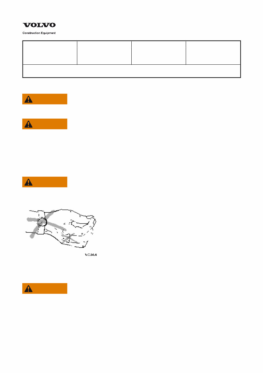
Service Information Document Title: Function Group: Information Type: Date: Electrical system, special instructions for servicing, general Service Information 2014/4/11 Profile: CEX, EC18C [GB] Electrical system, special instructions for servicing, general WARNING No changes may be made to the electrical system without prior approval from Volvo. Changes may affect machine functions and can result in risks for personal injury or machine damage. WARNING Carelessness when working with the electrical system may result in risks of serious personal injuries as well as machine damage. When working on the electrical system, the following instructions as well as instructions in respective section must be followed carefully. Also read instructions in Section Safety and in the Operator's Manual. WARNING Always remove watches, rings, bracelets and other metallic objects from the body before starting to work on the electrical system. Figure 1 WARNING Never boost-start the machine by connecting directly to the starter motor. This may result in uncontrolled machine movements. When using another machine to boost-start, it must not touch the machine that is being started. Never test if a cable/connection is supplied with electric power by producing "spark". This may permanently damaged electrical/electronic components.
Service Information Document Title: Function Group: Information Type: Date: Electrical system, special instructions for servicing, electrical components, batteries Service Information 2014/4/11 Profile: CEX, EC18C [GB] Electrical system, special instructions for servicing, electrical components, batteries WARNING During rapid charging of batteries, always remove the cell caps. During charging, an explosive mixture of oxygen and hydrogen is formed. A short-circuit, open flame or spark near the battery can cause a powerful explosion. Always turn off the charging current before disconnecting the charging clamps. Ventilate well, especially if the battery is being charged in a confined area. The battery electrolyte contains corrosive sulphuric acid. Remove spilled electrolyte from the skin immediately. Wash with soap and plenty of water. If electrolyte has splashed into the eyes or on any other sensitive body part, rinse immediately with plenty of water and contact a physician immediately. WARNING The batteries could explode due to the current surge if a fully charged battery is connected to a completely discharged battery. Since the batteries contain sulphuric acid, this could result in personal injuries. WARNING Never charge a frozen battery. Explosion hazard! Never disconnect the main electric current or disconnect battery cables when the engine is running. The battery's minus connection must always be disconnected before removing or installing components and connections in the electrical system. NOTE! Incorrect handling may cause damage to, for example, control unit/ECU which results in downtime. Fully charged batteries must be used when checking the electrical system. If the batteries are not fully charged, charge them or replace with new batteries. During battery charging, the battery terminal cables must always be disconnected from the battery. When changing batteries connected in series, the batteries should have the same capacity (for example, 150 Ah). The batteries should be of the same age (equally good). The reason for this is that the charging current required to give the battery a certain charge varies with the age of the battery. Only batteries may be used as assistant starting devices. An auxiliary starter unit and/or batteries connected in series to assist when starting may result in high (excess) voltage and can seriously damage electronic/electric components.
Service Information Document Title: Function Group: Information Type: Date: Electrical system, special instructions for servicing, electronic components Service Information 2014/4/11 Profile: CEX, EC18C [GB] Electrical system, special instructions for servicing, electronic components If a connector on any of the data buses has been damaged, the bus must be replaced. Note that the two cables included in each data bus are paired and twisted in order to protect them from electrical interference. Cabling must only be repaired by trained personnel. As an alternative, the entire cable harness can be completely replaced. NOTE! Electronic equipment is sensitive and may easily be damaged by electro-magnetic fields and/or by static electricity from tools or the human body. Therefore, always follow the instructions below when performing work involving electronic components. The following instructions must be followed in order to meet the requirements for electro-magnetic compatibility (EMC). Connections to an electronic component must never be disconnected when the unit is supplied with electric power, this may damage the electronics. Discharge any static electricity in tools before servicing the electrical system by touching the tool to a metallic machine part that is connected to the frame. Never touch the connector pins on electronic units. Avoid touching circuit boards when servicing the electrical system. If this is necessary – only hold the circuit board by the edges. Never touch individual electronic components. Make sure that ground cables are securely connected when replacing units. Never replace paired, twisted cabling with paired, non-twisted cabling.
Service Information Document Title: Function Group: Information Type: Date: Electrical system, special instructions for servicing, action when working on machine Service Information 2014/4/11 Profile: CEX, EC18C [GB] Electrical system, special instructions for servicing, action when working on machine For electric welding on the machine, the battery cables must be disconnected and the connectors must be unplugged from the control units. During blasting work on the machine, work very carefully to prevent damage to electrical cabling and components. Never aim the water jet directly at electrical components when using a high-pressure washer. This is especially important when using a combination of warm water and degreasing agents. Before drilling or making any other holes in the machine, all electrical components in the area must be located with great accuracy. NOTICE Drilling and other modifications to the cab structure are forbidden! The reason is that the ROPS protection may not function as intended if the cab structure is modified.
Service Information Document Title: Function Group: Information Type: Date: Troubleshooting, general 302 Service Information 2014/4/11 Profile: CEX, EC18C [GB] Troubleshooting, general The “Troubleshooting” section describes how troubleshooting is performed for symptoms and malfunction related to the machine’s electrical system. There is also information about the functions of the different electrical components, measuring values and possible malfunction detection. The starting point of all troubleshooting is that there is some type of trouble symptom or malfunction. Malfunctions can be indicated by: Red central warning flashes Buzzer sounds Detection of a malfunction symptom When a malfunction is suspected or has been confirmed, it is important to identify the cause as soon as possible. The first step in troubleshooting is to gather information from the operator concerning the malfunction symptoms. Then, attempt to pin-point the cause by performing checks in a certain order. The different checking steps are: Perform basic check Troubleshoot using a symptom guide
Service Information Document Title: Function Group: Information Type: Date: Collection of basic data 302 Service Information 2014/4/11 Profile: CEX, EC18C [GB] Collection of basic data General Figure 1 Collection of basic data Collection of basic data is the first step in all troubleshooting. This is done to quickly get an improved overall picture of how the problem shows up. In addition to information about the excavator and customer, it is important to gather as much information as possible with regards to the circumstances and sequence of events when the malfunction occurred. Often, the operator can provide valuable information regarding the circumstances when the malfunction occurred. The operator is almost always the one who notices a malfunction first. Since it is seldom possible to recreate the experienced problems, without having exactly the same conditions, the information from the operator is of great importance in order to be able to make correct evaluations for continued troubleshooting. Interview the operator using the following questions. Note the answers in writing and keep them together with the work order. The operator should be able to answer the following questions: General data Customer information Information about the dealer Operator Machine specifications: Machine Serial number Operating hours Engine type Engine number Model year Delivery date
Description of malfunction or symptom Describe the malfunction. When did the malfunction occur? How was the malfunction noticed and what happened just before it was noticed? Does the malfunction reappear? How often does the malfunction occur? For how long does the malfunction last when it occurs? Does the malfunction always occur during the same conditions, and what are those conditions? Does the operator have an idea of what may be the probable cause of the malfunction? Does the problem still exist? Engine information Under what operating conditions does the malfunction occur? External circumstances that affect the malfunction? Is the engine difficult to start? Is there abnormal smoke development? Are there abnormal sounds from the engine? Have changes in fuel consumption, oil consumption or engine power been confirmed? What type of fuel is used? Are additives used in the fuel? If yes, which ones? What previous repairs, adjustments/service have been done to the engine? Other information?
Service Information Document Title: Function Group: Information Type: Date: Troubleshooting tips 302 Service Information 2014/4/11 Profile: CEX, EC18C [GB] Troubleshooting tips General fault diagnosis information Examine the system: Read the service manual → check the main electrical wiring diagram → become acquainted with the function of the components. Analyse the complaint: Ask the driver → When did the problem first occur → What is the malfunction → Were parts repaired or replaced lately → If yes, why? Examine the machine: Check battery, fuses, connecting pins of plug connectors, wiring looms, switches etc. → Check also other systems. E.g. no fuel Start the machine: Listen → Watch → Try to sense the effect of the fault symptom. Try to narrow down the cause of the fault: Look for the most obvious reasons first → Avoid unnecessary replacement of parts → Use appropriate tools and the correct circuit diagrams to find the main cause. Objective: To isolate and identify a fault(s) on one (several) component(s). Malfunctions in electrical control circuits, high resistance in the electrical circuit 1. 2. 3. A high resistance in the electrical circuit can result in weak lighting and slow or non-functioning components. Fault: Loose, corroded, soiled or oily connections. Poor connection to ground Wrong cable cross section Broken flexible leads in a cable To localize the fault: Measure the voltage in the power circuit at various points in order to localize the section with a voltage drop, e.g. via the plug connection in a wiring loom. Malfunctions of electrical control circuits, interrupted electrical circuits 1. 2. 3. An interrupted electrical circuit has the effect that no component in this circuit will work. Fault: Blown-out fuse, disconnected cable, plug connection without connection, loose connecting pin on a component or ground cable without connection. To localize the fault: Check visually for blown fuses, loose connections or cables. Perform voltage tests in this electric circuit to check the continuity. If there is no continuity measure along the electrical circuit until continuity is found. Malfunction in the electrical system, electrical circuit short to ground 1. 2. A short to ground in an electrical circuit will cause blowing of the fuse and blow out the spare fuse after replacement. Fault: A conducting cable with the insulation worn off down to the unprotected conductor in contact with the chassis or a squashed cable on which the insulation has been cut open.
3. To localize the fault: Check the wiring looms visually for worn or squashed sections. Pay special attention to locations where the wiring loom passes through clamps, bushings or close to hot components, such as exhaust or radiator. Remove the fuse and disconnect the plug connections of the wiring loom at several places and check each location for ground connection. Malfunction of the electrical system, short circuits 1. 2. 3. A short circuit in an electric circuit has the effect that components in separate electrical circuits will be actuated when switching only one of the switches in an electrical circuit. NOTE! Components can also cause a short circuit to ground, but in such a case the fuse normally blows. Fault: Two wiring looms rubbing against each other until the insulation is chafed through, so that the electrical conductors have contact between each other. To localize the fault: Disconnect the cable to the switch for the component that should not be active. Disconnect the plug connections in the wiring loom of the electrical circuit until the component is switched off. The short circuit should be located between the two points at which the electrical circuit was interrupted.
Service Information Document Title: Function Group: Information Type: Date: Troubleshooting, assistant devices 302 Service Information 2014/4/11 Profile: CEX, EC18C [GB] Troubleshooting, assistant devices Service manual All information available for troubleshooting is available in the service manual. The different types of information are as follows: Special tools for troubleshooting These are the tools that are used for measuring of wire harness and components when the malfunction occurs. Collection of basic data These are the questions that you should ask the operator in order to investigate the nature of the malfunction and the conditions during which the malfunction occurs. Wiring diagrams Wiring diagrams are a great help when troubleshooting. In wiring diagrams, designations and color markings of electrical cabling are available, as well as component and connector designations. Component list In conjunction to the wiring diagrams, there is a component list that shows the positions of components on the machine. Component specifications The component specifications include measurement values and eventual calibration values for different components. Component checks Component checks are used for direct troubleshooting of a component in the electrical system. Connectors list Description of connector appearance and configuration. Symptom checks An error symptom can have one or several causes and troubleshooting using symptoms entails, in short, that by confirming or excluding different error sources, the error sources should lead to the cause of the symptom. Troubleshooting using symptoms, means in many cases, that one or several systems have to be checked in order to ensure that nothing is left out while troubleshooting, which would mean having to check the same system or component several times. For the systems and components where troubleshooting using symptoms is used, checklists are available for the symptoms that usually occur in case of a malfunction. In many cases, the same symptom is noticed though the causes may be different. Of course, a single malfunction may generate several different symptoms.
This is a comprehensive service repair manual for the VOLVO EC18C COMPACT EXCAVATOR. The manual features easy-to-read text sections with high-quality diagrams and instructions, making it suitable for both do-it-yourself enthusiasts and experienced mechanics. It provides step-by-step instructions, detailed exploded pictures, and diagrams to effectively complete the required job.
The VOLVO EC18C COMPACT EXCAVATOR repair manual covers every single detail of the machine and includes safety information, general details, standard parts and service, engine with mounting and equipment, electrical system, warning system, information system, instruments, power transmission, frame and crawler unit, cab, engine hood, hydraulic system, digging, handling, grading equipment, miscellaneous equipment, as well as hydraulic and electrical schematics.
This professional technical manual contains service, maintenance, and troubleshooting information for the VOLVO EC18C COMPACT EXCAVATOR, encompassing all models, engines, trims, and transmission types. It is a top-quality workshop repair service manual that is complete and intact without any missing or corrupt parts or pages. The manual is the same as the one used in local service and repair shops, guaranteeing full functionality to save time.
The VOLVO EC18C COMPACT EXCAVATOR repair manual is compatible with all versions of Windows and Mac. It is available in English language and can be printed without any restrictions. The file format is either .OVA or .PDF, and it requires Adobe Reader and Win to access. Upon purchase, the delivery link will appear on the checkout page after payment is complete.
Buyers can conveniently pay for the product via PayPal or Credit Card. Payments are accepted on behalf of merchants, and payouts are sent once per week. By clicking on the instant payment button, buyers can pay with PayPal or a credit card and receive the download link instantly.
Recently Viewed
5,521,897Happy Clients
2,594,462eManuals
1,120,453Trusted Sellers
15Years in Business
Price:
Actual Price:
VOLVO EC18C COMPACT Excavator Service Repair Manual