330-1-00-00-33
Table of Contents
/ 8
Second Edition : 05/2006
Table of Contents
Table of Contents
SH330SH350
Book No. WLST3303B-01W
Main Body Section
Page
Specifications
Specifications (SH330-3B) ........................................... 330-1-01-00-61 1/6 1
Complete Machine Dimensions .................................... 300-1-01-01-19
Standard Arm (3.25 m) ..................................................................... 1/3 7
Short Arm (2.63 m) ........................................................................... 2/3 8
Long Arm (4.04 m) ............................................................................ 3/3 9
Work Range .................................................................. 300-1-01-02-19
Standard Arm (3.25 m) ..................................................................... 1/3 10
Short Arm (2.63 m) ........................................................................... 2/3 11
Long Arm (4.04 m) ........................................................................... 3/3 12
Specifications (SH330LC-3B) ....................................... 330-1-01-00-62 1/6 13
Complete Machine Dimensions .................................... 300-1-01-01-20
LC Standard Arm (3.25 m) ................................................................ 1/3 19
LC Short Arm (2.63 m) ...................................................................... 2/3 20
LC Long Arm (4.04 m) ...................................................................... 3/3 21
Work Range .................................................................. 300-1-01-02-20
LC Standard Arm (3.25 m) ................................................................ 1/3 22
LC Short Arm (2.63 m) ...................................................................... 2/3 23
LC Long Arm (4.04 m) ...................................................................... 3/3 24
Specifications (SH350HD-3B) ...................................... 350-1-01-00-63 1/6 25
Complete Machine Dimensions .................................... 350-1-01-01-21
HD Standard Arm (3.25 m) ............................................................... 1/2 31
HD Short Arm (2.63 m) ..................................................................... 2/2 32
Work Range .................................................................. 350-1-01-02-21
HD Standard Arm (3.25 m) ............................................................... 1/2 33
HD Short Arm (2.63 m) ..................................................................... 2/2 34
Optional Components ................................................... 330-1-01-03-31
List of Optional Components ............................................................. 1/1 35
Page No. 1
330-1-00-00-33
Table of Contents
/ 8
Second Edition : 05/2006
Page
Emission Control Regulation of 3rd-Stage ...... 330-1-01-06-04
Execution Time Emission Control Regulation ....................................... 1/12 36
Standard Amount of Exhaust Gas ......................................................... 2/12 37
Measures to be Taken for The Emission Control Regulation
........................................................................................................ 3/12 38
Engine Fuel and Maintenance of Fuel Filters ........................................ 4/12 39
Engine System Diagram ........................................................................ 7/12 42
Construction of Engine .......................................................................... 8/12 43
Common Rail Injection System ............................................................. 9/12 44
Suction and Exhaust System ................................................................. 11/12 46
Page No. 2
330-1-00-00-33
Table of Contents
/ 8
Second Edition : 05/2006
Page
Major Equipment Specifications
Equipment Configuration .............................................. 300-2-01-00-05
Overall ............................................................................................... 1/2 48
Operator's Cab .................................................................................. 2/2 49
Lower Mechanism ........................................................ 330-2-01-01-49
Assembly Drawing ............................................................................ 1/4 50
Travel Unit ......................................................................................... 3/4 52
Take-up Roller .................................................................................. 3/4 52
Upper-Roller ...................................................................................... 3/4 52
Lower Roller ...................................................................................... 3/4 52
Recoil Spring ..................................................................................... 4/4 53
Shoes ................................................................................................ 4/4 53
Upper Mechanism ........................................................ 330-2-01-02-43
Swing Unit ......................................................................................... 1/1 54
Engine and Related Areas ............................................ 330-2-01-03-48
Engine ............................................................................................... 1/3 55
Muffler ............................................................................................... 1/3 55
Air Cleaner ........................................................................................ 2/3 56
Radiator ............................................................................................ 2/3 56
Fuel Tank .......................................................................................... 3/3 57
Hydraulic System .......................................................... 330-2-01-04-49
Hydraulic Pump ................................................................................. 1/3 58
Sump Tank ........................................................................................ 2/3 59
Rotating Joint .................................................................................... 3/3 60
Solenoid Valve .................................................................................. 3/3 60
Controls ........................................................................ 330-2-01-05-47
Control Valve .................................................................................... 1/2 61
Remote Control Valve (Left / Right, Travel Operations) ................... 2/2 62
Backhoe Attachments ................................................... 330-2-01-06-51
Cylinder ............................................................................................. 1/2 63
Attachments ...................................................................................... 2/2 64
Page No. 3
330-1-00-00-33
Table of Contents
/ 8
Second Edition : 05/2006
Hydraulics Section
Page
Hydraulic Pump .......................................................... 330-1-02-01-19
Structure and Principle of the Function ................................................. 1/2 65
Control Valve ............................................................... 330-1-02-02-16
Operation ............................................................................................... 1/21 67
Single Operation .................................................................................... 4/21 70
Combined Operation ............................................................................. 16/21 82
Anti-drift Valve ....................................................................................... 17/21 83
Relief Valve ........................................................................................... 18/21 84
Swing Unit .................................................................... 330-1-02-03-13
Configuration of Components ................................................................ 1/5 88
Structure of Hydraulic Motor .................................................................. 1/5 88
Operational Description of Hydraulic Motor ........................................... 1/5 88
Operational Description of Mechanical Brake ....................................... 2/5 89
Operational Description of Make-up Valve ............................................ 2/5 89
Operational Description of Relief Valve ................................................. 3/5 90
Operational Description of Bypass Valve .............................................. 3/5 90
Internal Structural Drawing .................................................................... 4/5 91
Internal Structural Drawing of
Externally Adjusted Shockless Relief Valve .......................................... 5/5 92
Internal Structural Drawing of Bypass Valve ......................................... 5/5 92
Travel Unit .................................................................... 330-1-02-04-16
Structure ................................................................................................ 1/12 93
Brief Explanation of Structure ................................................................ 2/12 94
Function ................................................................................................. 5/12 97
Page No. 4
330-1-00-00-33
Table of Contents
/ 8
Second Edition : 05/2006
Hydraulic Circuits Section
Page
Port Locations ............................................................. 330-1-03-00-24
Hydraulic Pump ..................................................................................... 1/2 105
Control Valve ......................................................................................... 2/2 106
Pilot Hose Connection Diagrams ........................ 330-1-03-01-30
Pilot P&T Lines ...................................................................................... 1/4 107
Pilot Control Lines ................................................................................. 3/4 109
Functional Explanations ......................................... 330-1-03-02-26
Functional Table .................................................................................... 1/2 111
Travel Circuits ............................................................. 330-1-03-03-23
High Speed Travel Circuit ...................................................................... 1/6 113
Low Speed Travel Circuit ...................................................................... 3/6 115
Straight Travel Circuit ............................................................................ 5/6 117
Swing Circuits ............................................................. 330-1-03-04-24
Swing Parking Circuit (Lever in Neutral / Swing Locked) ...................... 1/6 119
Swing Parking Circuit (Brake Released) ............................................... 3/6 121
Swing Push Digging .............................................................................. 5/6 123
Arm Circuits ................................................................. 330-1-03-06-23
Arm-Out Circuit ...................................................................................... 1/6 125
Arm-In Load Holding .............................................................................. 3/6 127
Arm-In Circuit ......................................................................................... 5/6 129
Boom Circuits ............................................................. 330-1-03-07-23
Boom-Up Circuit (Single) ....................................................................... 1/8 131
Boom-Up Circuit (Combined) ................................................................ 3/8 133
Boom-Down Load Holding ..................................................................... 5/8 135
Boom-Down Circuit ................................................................................ 7/8 137
Backup Circuits .......................................................... 330-1-03-09-17
Combined Circuit (Breaker Circuit) ........................................................ 1/4 139
Combined Circuit (High Speed Confluence Circuit) .............................. 3/4 141
Circuit Diagrams (Located inside the pocket at back of back cover)
Hydraulic Circuit Diagram (A1)
Page No. 5
330-1-00-00-33
Table of Contents
/ 8
Second Edition : 05/2006
Electric Circuits Section
Page
Operation Explanation ............................................. 330-1-04-01-27
System Chart of Functions .................................................................... 1/46 143
Engine Control ....................................................................................... 4/46 146
Work Mode Selection ............................................................................ 11/46 153
1. H / S / L Modes ............................................................................. 13/46 155
2. Auto Modes ................................................................................... 13/46 155
3. Load Prefetch Control ................................................................... 16/46 158
Throttle Control ...................................................................................... 17/46 159
Idling Control (Auto / One-touch) ........................................................... 20/46 162
Breaker Mode ........................................................................................ 22/46 164
Auto Preheat (Glow Control) ................................................................. 23/46 165
Auto Warm-up ....................................................................................... 26/46 168
Overheat Protection ............................................................................... 27/46 169
Atmospheric Pressure Compensation ................................................... 28/46 170
Control When Starting Engine ............................................................... 29/46 171
Control When Stopping Engine ............................................................. 30/46 172
Emergency Stop of the Engine .............................................................. 30/46 172
Engine Protection Function (EPF) ......................................................... 31/46 173
Lever Lock ............................................................................................. 33/46 175
Auto Boost Control ................................................................................ 34/46 176
Swing Lock ............................................................................................ 35/46 177
Swing Brake Control .............................................................................. 35/46 177
Travel Speed Switch-over ..................................................................... 37/46 179
Travel Alarm .......................................................................................... 38/46 180
Power Shut-off Delay ............................................................................. 39/46 181
Fuel Supply Pump Control (Automatic stop) Option .............................. 40/46 182
Power Transistor Protection .................................................................. 42/46 184
Monitor Display ...................................................................................... 43/46 185
1. Normal Display .............................................................................. 43/46 185
2. Message Display ........................................................................... 46/46 188
Page No. 6
330-1-00-00-33
Table of Contents
/ 8
Second Edition : 05/2006
Service Support .......................................................... 800-1-04-04-08
Summary ............................................................................................... 1/20 189
Operating Instructions ........................................................................... 2/20 190
Measuring Electrical Device .................................. 330-1-04-02-18
Instruments to be Measured .................................................................. 1/14 209
Equipment for Measuring ...................................................................... 1/14 209
Measuring Methods ............................................................................... 10/14 218
Initial Controller Settings ........................................ 700-1-04-05-07
Verifying the Settings ............................................................................. 1/3 223
Resetting Procedures ............................................................................ 1/3 223
Setting Procedures ................................................................................ 1/3 223
List of Settings ....................................................................................... 2/3 224
Error Display Functions ......................................................................... 3/3 225
Troubleshooting ......................................................... 330-1-04-06-12
Problem Symptoms ............................................................................... 1/12 226
Inspections Prior to Troubleshooting ..................................................... 2/12 227
Troubleshooting Procedures ................................................................. 3/12 228
Using the Flow Chart ............................................................................. 4/12 229
Diagnosis ............................................................................................... 5/12 230
1. Refuel ............................................................................................ 5/12 230
2. Refilling Coolant ............................................................................ 6/12 231
3. Low Engine Oil Pressure .............................................................. 7/12 232
4. Overheat ....................................................................................... 8/12 233
5. Battery Charging ........................................................................... 10/12 235
6. Faulty Electrical System ................................................................ 11/12 236
Electric Wiring Diagrams ........................................ 330-1-04-07-21
Electrical Components and Wiring (Frame) ........................................... 1/2 238
Electrical Components and Wiring (Cab) .............................................. 2/2 239
Harness Diagrams ..................................................... 330-1-04-08-21
Frame Main Harness ............................................................................. 1/2 240
Cab Main Harness ................................................................................. 2/2 241
Circuit Diagrams (Located inside the pocket at back of back cover)
Electric Circuits Diagram (A1)
Page No. 7
330-1-00-00-33
Table of Contents
/ 8
Second Edition : 05/2006
Maintenance Section
Page
New Machine Performance
Performance Evaluation Check Sheet .......................... 000-3-02-00-15 1/2 242
Reference Values ......................................................... 330-3-02-01-26 1/1 244
Instructions for Measuring and Adjusting Pressure
............................................................................... 330-1-05-00-29
Measuring Pressure .............................................................................. 1/14 245
1. Basic Conditions ........................................................................... 1/14 245
2. Set Values ..................................................................................... 1/14 245
3. Pressure Measuring Port .............................................................. 2/14 246
4. Preparation for Measuring Pressure ............................................. 4/14 248
5. Measuring Pressure ...................................................................... 6/14 250
6. Measuring Other Pressures .......................................................... 8/14 252
Adjusting Pressure ................................................................................ 9/14 253
1. Pressure Adjusting Points ............................................................. 9/14 253
2. Instructions for Adjusting Pressure ............................................... 11/14 255
Maintenance of The Circumference of Engine
............................................................................... 330-1-05-07-04
Circumference Filter Arrangement of Engine ........................................ 1/3 259
Fuel Element System Diagram .............................................................. 2/3 260
Main Body Weight ..................................................... 330-3-01-00-51
Major Component Weight ...................................................................... 1/3 262
Individual Part Weight ............................................................................ 2/3 263
Shoe Weight (One side) ........................................................................ 2/3 263
Arm Weight ............................................................................................ 2/3 263
Bucket Weight ....................................................................................... 3/3 264
Attachments Dimensions ....................................... 330-1-05-04-19 1/1 265
Compatibility ............................................................... 330-1-05-05-27 1/2 266
Plastic Shim ................................................................. 000-1-05-08-02 1/1 268
Procedures for Changing Operation Type ....... 000-8-02-01-07
ISO Type ............................................................................................... 1/4 269
Old Sumitomo Type ............................................................................... 2/4 270
Old Mitsubishi Type ............................................................................... 3/4 271
Old Kobelco Type .................................................................................. 4/4 272
Page No. 8
107
330-1-03-01-30
Hydraulic Circuits
/ 4
First Edition : 03/2006
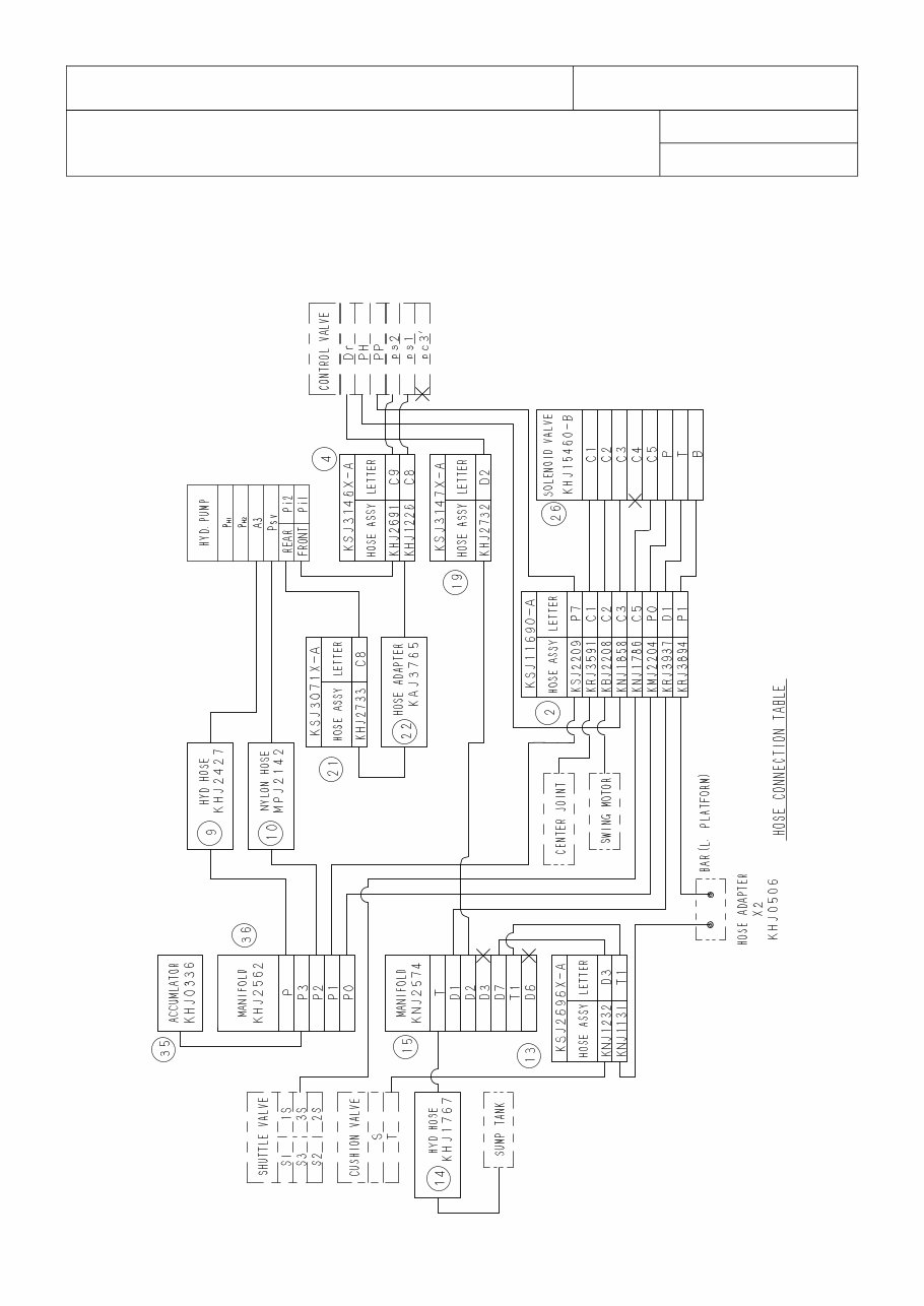
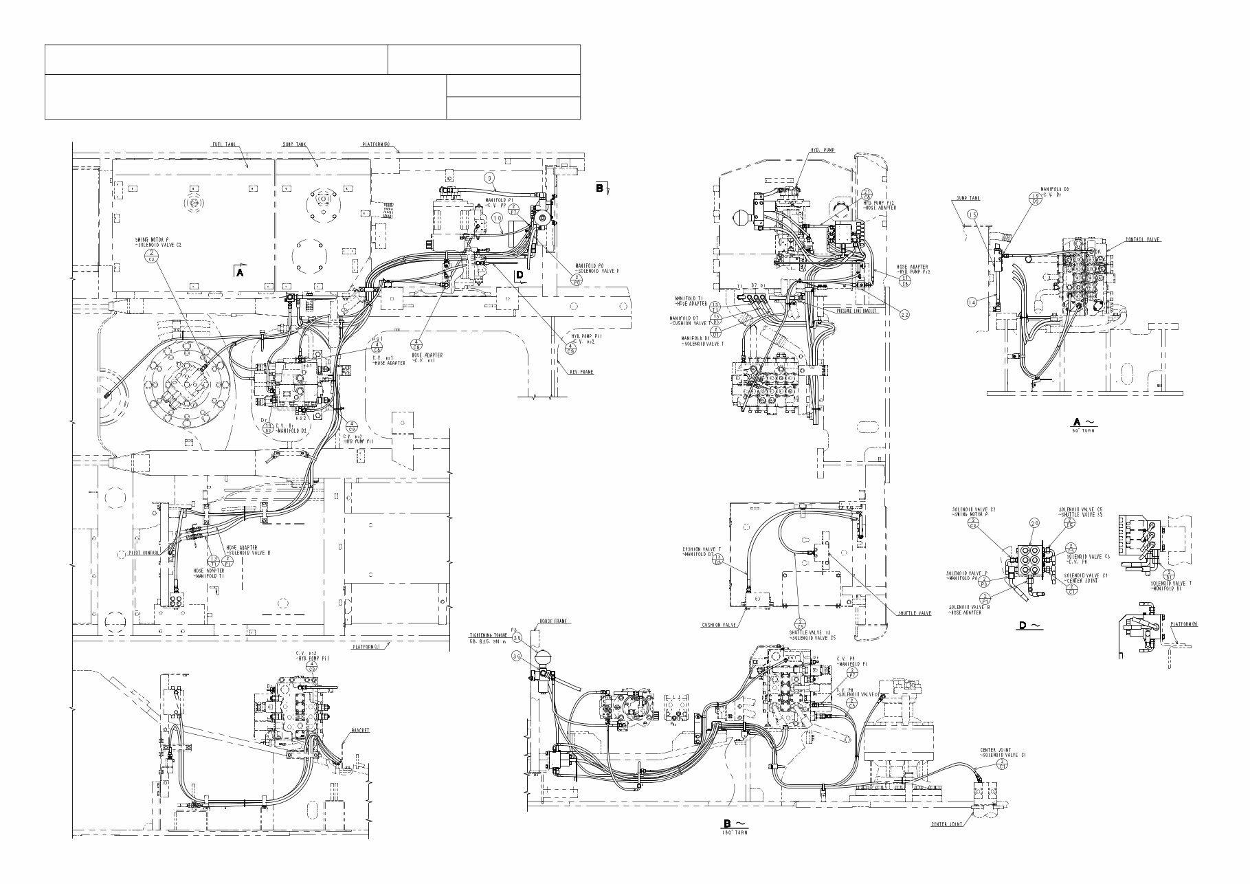
PILOT HOSE CONNECTION DIAGRAMS
Hydraulic Circuits
PILOT HOSE CONNECTION DIAGRAMS
PILOT HOSE CONNECTION DIAGRAMS
SH330SH350
Pilot P&T Lines
KSJ3143Z-E04
Page No. 1
330-1-03-01-30
/ 4
First Edition : 03/2006
108
Hydraulic Circuits
PILOT HOSE CONNECTION DIAGRAMS
KSJ3143Z-E04
Page No. 2
You're Reading a Preview
What's Included?
Lifetime Access
Access PDF Contents & Bookmarks
Print one or all pages of your manual