

New Holland CE EH35, EH45 Operators Manual
What's Included?
Fast Download Speeds
Online & Offline Access
Access PDF Contents & Bookmarks
Full Search Facility
Print one or all pages of your manual

CONSTRUCTION CONSTRUCTION
OPERATOR'S
MANUAL
EH35/EH45
COMPACT EXCAVATORS
6-82080NA

EH35 AND EH45
EXCAVATORS
OPERATOR’S MANUAL
NOTE: New Holland, LLC. reserves the right to make improvements in design or changes in
specifications at any time without incurring any obligation to install them on units previously sold.
NEW HOLLAND, LLC. TECHNICAL MANUALS
Manuals are available from your Dealer for the operation, service, and repair of your machine. For
prompt convenient service, contact your Dealer for assistance in obtaining the manuals for your
machine.
Your Dealer can expedite your order for Operator’s Manuals, Parts Catalogs, Service Manuals, and
Maintenance records.
Always give the Machine Name, Model, and P.I.N. (Product Identification Number) or S.N. (Serial
Number) of your machine so your Dealer can provide the correct manuals for your machine.
Part Number: 6-82080
CALIFORNIA
PROPOSITION 65 WARNING
Diesel engine exhaust and some of its constituents are known to the State of
California to cause cancer, birth defects, and other reproductive harm.
Battery post, terminals and related accessories contain lead and lead compounds.
Wash hands after handling.
Copyright © 2003 New Holland, LLC. Bur 6-82080NA
All Rights Reserved Issued November, 2003
New Holland is a registered trademark of New Holland, LLC.
M171D
Safety Decals on this machine use the words Danger, Warning, or Caution, which are defined as follows:
● DANGER: Indicates an immediate hazardous situation that, if not avoided, will result in death or
serious injury. The color associated with Danger is RED.
● WARNING: Indicates a potentially hazardous situation that, if not avoided, could result in death or
serious injury. The color associated with Warning is ORANGE.
● CAUTION: Indicates a potentially hazardous situation which, if not avoided, may result in minor or
moderate injury. It may also be used to alert against unsafe practices. The color associated with
Caution is YELLOW.
If Safety Decals on this machine are ISO two panel Pictorial, decals are defined as follows:
● The first panel indicates the nature of the hazard.
● The second panel indicates the appropriate avoidance of the hazard.
● Background color is YELLOW
● Prohibition symbols such as and if used, are RED.
WARNING_01_NA
THIS SAFETY ALERT SYMBOL INDICATES IMPORTANT SAFETY MESSAGES IN THIS MANUAL.
WHEN YOU SEE THIS SYMBOL, CAREFULLY READ THE MESSAGE THAT FOLLOWS AND BE
ALERT TO THE POSSIBILITY OF DEATH OR SERIOUS INJURY
IMPROPER OPERATION OF THIS MACHINE CAN CAUSE DEATH OR SERIOUS INJURY. BEFORE
USING THIS MACHINE, MAKE CERTAIN THAT EVERY OPERATOR:
● Is instructed in safe and proper use of the machine.
● Reads and understands the Manual(s) pertaining to the machine.
● Reads and understands ALL Safety Decals on the machine.
● Clears the area of other persons.
● Learns and practices safe use of machine controls in a safe, clear area before operating this
machine on a job site.
It is your responsibility to observe pertinent laws and regulations and follow New Holland, LLC.
instructions on machine operation and maintenance.
STOP

I
6-82080NA Issued 11-03 Bur
TABLE OF CONTENTS
CHAPTER 1
GENERAL INFORMATION
To the Owner . . . . . . . . . . . . . . . . . . . . . . . . . . . . . . . . . . . . . . . . . . . . . . . . . . . . . . . . . . . . . . . . . . . . . . . . 1-1
Right, Left, Front, and Rear of the Machine . . . . . . . . . . . . . . . . . . . . . . . . . . . . . . . . . . . . . . . . . . . . . . . . . 1-2
Machine Components . . . . . . . . . . . . . . . . . . . . . . . . . . . . . . . . . . . . . . . . . . . . . . . . . . . . . . . . . . . . . . . . . 1-3
Identification Numbers . . . . . . . . . . . . . . . . . . . . . . . . . . . . . . . . . . . . . . . . . . . . . . . . . . . . . . . . . . . . . . . . . 1-5
CHAPTER 2
SAFETY, DECALS, AND HAND SIGNALS
Table of Contents . . . . . . . . . . . . . . . . . . . . . . . . . . . . . . . . . . . . . . . . . . . . . . . . . . . . . . . . . . . . . . . . . . . . . 2-1
Safety Rules . . . . . . . . . . . . . . . . . . . . . . . . . . . . . . . . . . . . . . . . . . . . . . . . . . . . . . . . . . . . . . . . . . . . . . . . . 2-3
Personal Safety . . . . . . . . . . . . . . . . . . . . . . . . . . . . . . . . . . . . . . . . . . . . . . . . . . . . . . . . . . . . . . . . . . . . . . 2-3
Safety Area . . . . . . . . . . . . . . . . . . . . . . . . . . . . . . . . . . . . . . . . . . . . . . . . . . . . . . . . . . . . . . . . . . . . . . . . . 2-3
Utility Safety . . . . . . . . . . . . . . . . . . . . . . . . . . . . . . . . . . . . . . . . . . . . . . . . . . . . . . . . . . . . . . . . . . . . . . . . . 2-4
Operator Precautions . . . . . . . . . . . . . . . . . . . . . . . . . . . . . . . . . . . . . . . . . . . . . . . . . . . . . . . . . . . . . . . . . . 2-4
Decals . . . . . . . . . . . . . . . . . . . . . . . . . . . . . . . . . . . . . . . . . . . . . . . . . . . . . . . . . . . . . . . . . . . . . . . . . . . . 2-10
CHAPTER 3
INSTRUMENTS AND CONTROLS
Table of Contents . . . . . . . . . . . . . . . . . . . . . . . . . . . . . . . . . . . . . . . . . . . . . . . . . . . . . . . . . . . . . . . . . . . . . 3-1
Cab (If Equipped) . . . . . . . . . . . . . . . . . . . . . . . . . . . . . . . . . . . . . . . . . . . . . . . . . . . . . . . . . . . . . . . . . . . . . 3-3
Steps and Access Handles . . . . . . . . . . . . . . . . . . . . . . . . . . . . . . . . . . . . . . . . . . . . . . . . . . . . . . . . . . . . . 3-5
Operator’s Compartment Controls and Accessories . . . . . . . . . . . . . . . . . . . . . . . . . . . . . . . . . . . . . . . . . . 3-6
Instrument Panel . . . . . . . . . . . . . . . . . . . . . . . . . . . . . . . . . . . . . . . . . . . . . . . . . . . . . . . . . . . . . . . . . . . . . 3-7
Switches . . . . . . . . . . . . . . . . . . . . . . . . . . . . . . . . . . . . . . . . . . . . . . . . . . . . . . . . . . . . . . . . . . . . . . . . . . . . 3-9
Control Levers . . . . . . . . . . . . . . . . . . . . . . . . . . . . . . . . . . . . . . . . . . . . . . . . . . . . . . . . . . . . . . . . . . . . . . 3-11
Access Covers and guards . . . . . . . . . . . . . . . . . . . . . . . . . . . . . . . . . . . . . . . . . . . . . . . . . . . . . . . . . . . . 3-14
Operator’s Seat Adjustment . . . . . . . . . . . . . . . . . . . . . . . . . . . . . . . . . . . . . . . . . . . . . . . . . . . . . . . . . . . . 3-15
Seat Belt . . . . . . . . . . . . . . . . . . . . . . . . . . . . . . . . . . . . . . . . . . . . . . . . . . . . . . . . . . . . . . . . . . . . . . . . . . 3-15
CHAPTER 4
OPERATING INSTRUCTIONS
Table of Contents . . . . . . . . . . . . . . . . . . . . . . . . . . . . . . . . . . . . . . . . . . . . . . . . . . . . . . . . . . . . . . . . . . . . . 4-1
Before Operating the Machine . . . . . . . . . . . . . . . . . . . . . . . . . . . . . . . . . . . . . . . . . . . . . . . . . . . . . . . . . . . 4-3
Operating the Machine . . . . . . . . . . . . . . . . . . . . . . . . . . . . . . . . . . . . . . . . . . . . . . . . . . . . . . . . . . . . . . . . . 4-3
Run-In Period . . . . . . . . . . . . . . . . . . . . . . . . . . . . . . . . . . . . . . . . . . . . . . . . . . . . . . . . . . . . . . . . . . . . . . . . 4-4
Starting the engine . . . . . . . . . . . . . . . . . . . . . . . . . . . . . . . . . . . . . . . . . . . . . . . . . . . . . . . . . . . . . . . . . . . . 4-4
Bringing the Machine Up To Operating Temperature . . . . . . . . . . . . . . . . . . . . . . . . . . . . . . . . . . . . . . . . . 4-6
Engine Operation . . . . . . . . . . . . . . . . . . . . . . . . . . . . . . . . . . . . . . . . . . . . . . . . . . . . . . . . . . . . . . . . . . . . . 4-7
Stopping the Engine . . . . . . . . . . . . . . . . . . . . . . . . . . . . . . . . . . . . . . . . . . . . . . . . . . . . . . . . . . . . . . . . . . . 4-7
Operating the Machine in Cold Weather . . . . . . . . . . . . . . . . . . . . . . . . . . . . . . . . . . . . . . . . . . . . . . . . . . . 4-8
Operating the Machine in Hot Weather . . . . . . . . . . . . . . . . . . . . . . . . . . . . . . . . . . . . . . . . . . . . . . . . . . . . 4-8
Operation . . . . . . . . . . . . . . . . . . . . . . . . . . . . . . . . . . . . . . . . . . . . . . . . . . . . . . . . . . . . . . . . . . . . . . . . . . . 4-8
Machine Travel . . . . . . . . . . . . . . . . . . . . . . . . . . . . . . . . . . . . . . . . . . . . . . . . . . . . . . . . . . . . . . . . . . . . . . 4-9
Transporting the Machine . . . . . . . . . . . . . . . . . . . . . . . . . . . . . . . . . . . . . . . . . . . . . . . . . . . . . . . . . . . . . 4-10
Operating the Machine in Water . . . . . . . . . . . . . . . . . . . . . . . . . . . . . . . . . . . . . . . . . . . . . . . . . . . . . . . . 4-13
Parking the Machine . . . . . . . . . . . . . . . . . . . . . . . . . . . . . . . . . . . . . . . . . . . . . . . . . . . . . . . . . . . . . . . . . 4-14
Operating the Machine on Sloping Ground . . . . . . . . . . . . . . . . . . . . . . . . . . . . . . . . . . . . . . . . . . . . . . . . 4-14
Moving A Disabled Machine . . . . . . . . . . . . . . . . . . . . . . . . . . . . . . . . . . . . . . . . . . . . . . . . . . . . . . . . . . . 4-14
Lowering the Attachment in the Event of a Machine Failure . . . . . . . . . . . . . . . . . . . . . . . . . . . . . . . . . . . 4-14
Operating the Bucket . . . . . . . . . . . . . . . . . . . . . . . . . . . . . . . . . . . . . . . . . . . . . . . . . . . . . . . . . . . . . . . . . 4-15
Machine Storage . . . . . . . . . . . . . . . . . . . . . . . . . . . . . . . . . . . . . . . . . . . . . . . . . . . . . . . . . . . . . . . . . . . . 4-16

II
Issued 11-03 Bur 6-82080NA
CHAPTER 5
LUBRICATION, FILTERS, AND FLUIDS
Table of Contents . . . . . . . . . . . . . . . . . . . . . . . . . . . . . . . . . . . . . . . . . . . . . . . . . . . . . . . . . . . . . . . . . . . . 5-1
Servicing Instructions . . . . . . . . . . . . . . . . . . . . . . . . . . . . . . . . . . . . . . . . . . . . . . . . . . . . . . . . . . . . . . . . . 5-3
Fluids and Lubricants . . . . . . . . . . . . . . . . . . . . . . . . . . . . . . . . . . . . . . . . . . . . . . . . . . . . . . . . . . . . . . . . . 5-4
Daily Inspections . . . . . . . . . . . . . . . . . . . . . . . . . . . . . . . . . . . . . . . . . . . . . . . . . . . . . . . . . . . . . . . . . . . . . 5-7
Lubrication and Maintenance Chart . . . . . . . . . . . . . . . . . . . . . . . . . . . . . . . . . . . . . . . . . . . . . . . . . . . . . . 5-8
Grease Fittings and Lubrication Points . . . . . . . . . . . . . . . . . . . . . . . . . . . . . . . . . . . . . . . . . . . . . . . . . . . 5-10
Engine Oil . . . . . . . . . . . . . . . . . . . . . . . . . . . . . . . . . . . . . . . . . . . . . . . . . . . . . . . . . . . . . . . . . . . . . . . . . 5-14
Cooling System . . . . . . . . . . . . . . . . . . . . . . . . . . . . . . . . . . . . . . . . . . . . . . . . . . . . . . . . . . . . . . . . . . . . . 5-16
Fuel System . . . . . . . . . . . . . . . . . . . . . . . . . . . . . . . . . . . . . . . . . . . . . . . . . . . . . . . . . . . . . . . . . . . . . . . 5-19
Releasing Pressure in the Hydraulic System . . . . . . . . . . . . . . . . . . . . . . . . . . . . . . . . . . . . . . . . . . . . . . 5-24
Hydraulic System . . . . . . . . . . . . . . . . . . . . . . . . . . . . . . . . . . . . . . . . . . . . . . . . . . . . . . . . . . . . . . . . . . . 5-25
Air Filter . . . . . . . . . . . . . . . . . . . . . . . . . . . . . . . . . . . . . . . . . . . . . . . . . . . . . . . . . . . . . . . . . . . . . . . . . . . 5-33
Travel Reduction Gears . . . . . . . . . . . . . . . . . . . . . . . . . . . . . . . . . . . . . . . . . . . . . . . . . . . . . . . . . . . . . . 5-34
CHAPTER 6
MAINTENANCE AND ADJUSTMENTS
Table of Contents . . . . . . . . . . . . . . . . . . . . . . . . . . . . . . . . . . . . . . . . . . . . . . . . . . . . . . . . . . . . . . . . . . . . 6-1
Tracks . . . . . . . . . . . . . . . . . . . . . . . . . . . . . . . . . . . . . . . . . . . . . . . . . . . . . . . . . . . . . . . . . . . . . . . . . . . . . 6-3
Checking the Condition of Rubber Tracks . . . . . . . . . . . . . . . . . . . . . . . . . . . . . . . . . . . . . . . . . . . . . . . . . 6-6
Track Rollers and idlers . . . . . . . . . . . . . . . . . . . . . . . . . . . . . . . . . . . . . . . . . . . . . . . . . . . . . . . . . . . . . . . 6-8
Replacing a Bucket . . . . . . . . . . . . . . . . . . . . . . . . . . . . . . . . . . . . . . . . . . . . . . . . . . . . . . . . . . . . . . . . . . . 6-9
Fan and alternator Drive Belt . . . . . . . . . . . . . . . . . . . . . . . . . . . . . . . . . . . . . . . . . . . . . . . . . . . . . . . . . . 6-11
Inspecting and Cleaning the Machine . . . . . . . . . . . . . . . . . . . . . . . . . . . . . . . . . . . . . . . . . . . . . . . . . . . . 6-11
Checking for Cylinder Leakage . . . . . . . . . . . . . . . . . . . . . . . . . . . . . . . . . . . . . . . . . . . . . . . . . . . . . . . . . 6-11
Fire Extinguisher (Not Supplied) . . . . . . . . . . . . . . . . . . . . . . . . . . . . . . . . . . . . . . . . . . . . . . . . . . . . . . . . 6-12
Plastic and Resin Parts . . . . . . . . . . . . . . . . . . . . . . . . . . . . . . . . . . . . . . . . . . . . . . . . . . . . . . . . . . . . . . . 6-12
Welding on the Machine . . . . . . . . . . . . . . . . . . . . . . . . . . . . . . . . . . . . . . . . . . . . . . . . . . . . . . . . . . . . . . 6-12
Metric Torque Specifications . . . . . . . . . . . . . . . . . . . . . . . . . . . . . . . . . . . . . . . . . . . . . . . . . . . . . . . . . . . 6-13
CHAPTER 7
ELECTRICAL
Table of Contents . . . . . . . . . . . . . . . . . . . . . . . . . . . . . . . . . . . . . . . . . . . . . . . . . . . . . . . . . . . . . . . . . . . . 7-1
Alternator . . . . . . . . . . . . . . . . . . . . . . . . . . . . . . . . . . . . . . . . . . . . . . . . . . . . . . . . . . . . . . . . . . . . . . . . . . 7-3
Starter Motor . . . . . . . . . . . . . . . . . . . . . . . . . . . . . . . . . . . . . . . . . . . . . . . . . . . . . . . . . . . . . . . . . . . . . . . . 7-3
Fuses . . . . . . . . . . . . . . . . . . . . . . . . . . . . . . . . . . . . . . . . . . . . . . . . . . . . . . . . . . . . . . . . . . . . . . . . . . . . . 7-3
Battery . . . . . . . . . . . . . . . . . . . . . . . . . . . . . . . . . . . . . . . . . . . . . . . . . . . . . . . . . . . . . . . . . . . . . . . . . . . . . 7-4
Connecting A Booster Battery . . . . . . . . . . . . . . . . . . . . . . . . . . . . . . . . . . . . . . . . . . . . . . . . . . . . . . . . . . . 7-6
Attachment (Boom) Lamp . . . . . . . . . . . . . . . . . . . . . . . . . . . . . . . . . . . . . . . . . . . . . . . . . . . . . . . . . . . . . . 7-7
CHAPTER 8
SPECIFICATIONS
Table of Contents . . . . . . . . . . . . . . . . . . . . . . . . . . . . . . . . . . . . . . . . . . . . . . . . . . . . . . . . . . . . . . . . . . . . 8-1
Engine . . . . . . . . . . . . . . . . . . . . . . . . . . . . . . . . . . . . . . . . . . . . . . . . . . . . . . . . . . . . . . . . . . . . . . . . . 8-3 - 8-4
Hydraulic Components . . . . . . . . . . . . . . . . . . . . . . . . . . . . . . . . . . . . . . . . . . . . . . . . . . . . . . . . . . . . 8-3 - 8-4
Speed and Gradeability . . . . . . . . . . . . . . . . . . . . . . . . . . . . . . . . . . . . . . . . . . . . . . . . . . . . . . . . . . . 8-3 - 8-4
Boom Swing and Dozer Blade . . . . . . . . . . . . . . . . . . . . . . . . . . . . . . . . . . . . . . . . . . . . . . . . . . . . . . 8-3 - 8-4
Machine Overall Dimensions - EH35 ROPS Canopy . . . . . . . . . . . . . . . . . . . . . . . . . . . . . . . . . . . . . . . . . 8-5
Machine Overall Dimensions - EH45 ROPS Canopy . . . . . . . . . . . . . . . . . . . . . . . . . . . . . . . . . . . . . . . . . 8-6
Machine Overall Dimensions - Cab Model . . . . . . . . . . . . . . . . . . . . . . . . . . . . . . . . . . . . . . . . . . . . . . . . . 8-7
Working Range . . . . . . . . . . . . . . . . . . . . . . . . . . . . . . . . . . . . . . . . . . . . . . . . . . . . . . . . . . . . . . . . . . . . . . 8-8
CHAPTER 9
INDEX
CHAPTER 1 - GENERAL INFORMATION
1-1
6-82080NA Issued 11-03 Bur
Chapter 1
GENERAL INFORMATION
TO THE OWNER
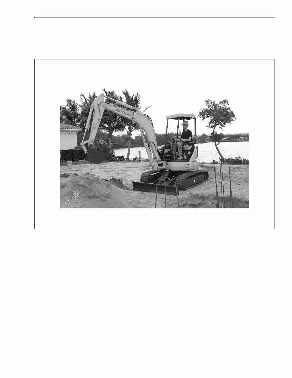
BD03M001
Figure 1
EH35 COMPACT HYDRAULIC CRAWLER EXCAVATOR
Your machine has been designed and built to the highest standards of quality. It conforms to all current safety
regulations. See Official documents. However, the risk of accidents can never be completely excluded. That is why
it is essential to observe elementary safety rules and precautions.
Read this manual carefully, paying particular attention to the instructions concerning safety, operation and
maintenance so as to avoid the risk of injury while operating or servicing the machine.
The standard attachments and tools of this machine are designed to carry out all kinds of earth moving and
rehandling operations. If you want to use this machine to handle a load (pipes, culverts, form work, etc.), make
sure that it is designed to carry out this kind of work. For this type of application, the machine must be equipped
with safety valves, an overload indicator, a load handling chart corresponding to the type of machine and its
attachment and a load fixing point. All legal requirements must also be strictly observed.
Do not use this machine for any application or purpose other than those described in this manual. If the machine is
to be used for work involving the use of special attachments, accessories or equipment, consult your New Holland,
LLC. Dealer in order to make sure that any adaptations or modifications made are in keeping with the machine's
technical specifications and with prevailing safety requirements.
Any modification or adaptation which is not approved by the manufacturer may invalidate the machine's initial
conformity with safety requirements.
The machine must undergo regular inspections, the frequency of which varies according to the type of use. Consult
your New Holland, LLC. Dealer.
CHAPTER 1 - GENERAL INFORMATION
1-2
Issued 11-03 Bur 6-82080NA
Before permitting a new operator on this machine, make sure:
That the operator has received the necessary training on how to operate the machine correctly and safely.
That the operator has read and understood the instructions given in this manual.
Always keep this manual in the operator's compartment (in the seat back, behind the operator's seat). Make sure it
is always complete and in good condition. If you wish to obtain extra copies, or copies in languages other than that
of the country of use, consult your New Holland, LLC. Dealer.
Your New Holland, LLC. Dealer is at your disposal for any further information. He will also provide any after-sales
service you may require, and genuine New Holland, LLC. spare parts, your guarantee of quality and match.
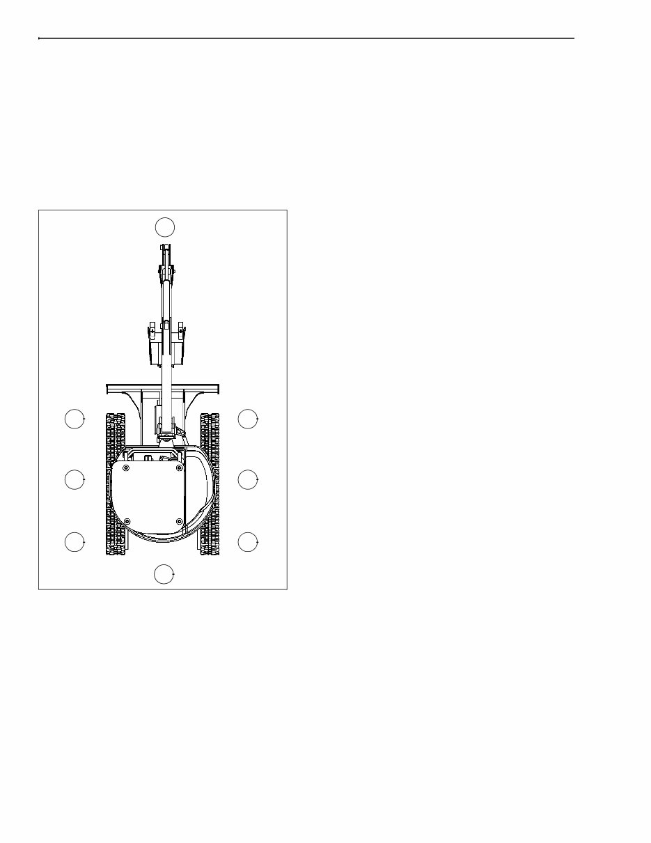
RIGHT, LEFT, FRONT, AND REAR OF THE MACHINE
BC02N192
Figure 2
1. FRONT
2. REAR
3. RIGHT-HAND SIDE
4. LEFT-HAND SIDE
5. TRAVEL REDUCTION GEARS (TRAVEL MOTORS)
6. IDLER WHEELS
The terms Right-hand, Left-hand, Front, and Rear
are used in this manual to indicate the sides as they
are seen from the operator's seat when the cab is
over the idler wheels.
The illustration below shows the machine in normal
TRAVEL position. In normal TRAVEL position, the
cab is over the idler wheels. The travel reduction
gears are at the rear of the upperstructure.
1
6 6
3 4
5 5
2
CHAPTER 1 - GENERAL INFORMATION
1-3
6-82080NA Issued 11-03 Bur
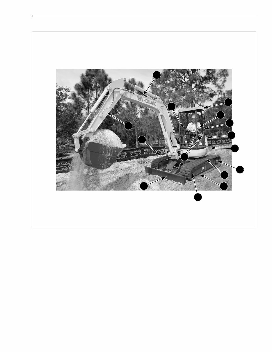
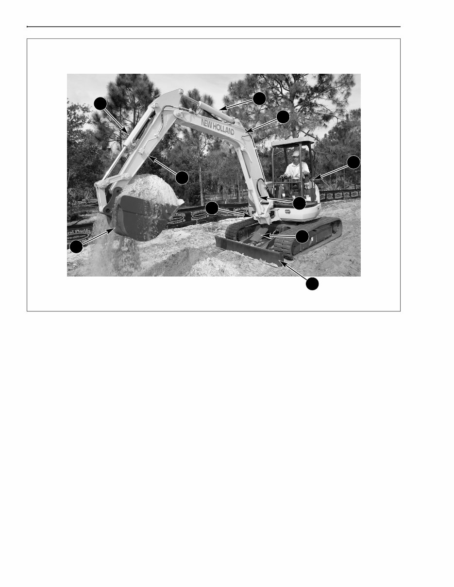
MACHINE COMPONENTS
BD03M002
Figure 3
EH45 COMPACT HYDRAULIC CRAWLER EXCAVATOR
MACHINE COMPONENTS
1. ROPS CANOPY 5. TRACK 9. DOZER BLADE 13. ACCESS HANDLES
2. OPERATOR’S MANUAL STORAGE 6. TRAVEL REDUCTION GEAR 10. STEP 14. LEFT CONTROL LEVER
3. UPPERSTRUCTURE 7. LOWER ROLLERS 11. ARM 15. RIGHT CONTROL LEVER
4. COUNTERWEIGHT 8. IDLER 12. BOOM
7 9
10
11
13
12
6
5
4
3
2
14
15
1
8
CHAPTER 1 - GENERAL INFORMATION
1-4
Issued 11-03 Bur 6-82080NA
BD03M002
Figure 4
EH35 AND EH45 MACHINE COMPONENTS
The EH compact excavator is a fully hydraulic machine. It consists of an undercarriage fitted with tracks and a
turntable bearing which supports the upperstructure frame. The upperstructure frame supports the attachment, at
the front end of the machine, plus the engine, hydraulics and cab. When the operator works the controls, the
engine-driven pump delivers hydraulic fluid to the control valves. The control valves distribute the hydraulic fluid to
the various cylinders and motors concerned. A cooling system maintains the hydraulic fluid at normal operating
temperature.
1. ACCESS HANDLE 5. ARM 9. DOZER BLADE
2. ARM CYLINDER 6. BOOM 10. BOOM SWING CYLINDER
3. BUCKET CYLINDER 7. BOOM CYLINDER
4. BUCKET 8. DOZER CYLINDER
6
7
3
2
1
4
5
8
10
9
CHAPTER 1 - GENERAL INFORMATION
1-5
6-82080NA Issued 11-03 Bur
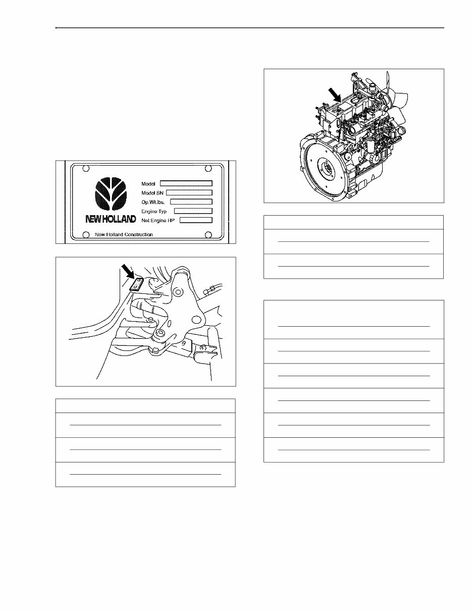
IDENTIFICATION NUMBERS
MODEL, SERIAL NUMBER, AND YEAR OF
MANUFACTURE
When ordering parts, obtaining information or
assistance, always supply your New Holland, LLC.
Dealer with the type and serial number of your
machine or accessories.
Write the following in the spaces below: The type,
serial number and year of manufacture of your
machine, accessories and the serial numbers of the
various hydraulic and mechanical components.
HR1201NH
Figure 5
BC02N194
Figure 6
ENGINE
BC02N196
Figure 7
COMPONENT SERIAL NUMBERS
PRODUCT IDENTIFICATION PLATE
➤
Model
➤
Serial Number
➤
Manufacturing Year
ENGINE
➤
Make and Model
➤
Serial Number
COMPONENT SERIAL NUMBERS
➤
Hydraulic Pump
➤
Swing Reduction Gear
➤
Travel Reduction Gears
➤
Travel Control Valve
➤
Attachment Control Valve
➤
Swing Control Valve
You're Reading a Preview
What's Included?
Fast Download Speeds
Online & Offline Access
Access PDF Contents & Bookmarks
Full Search Facility
Print one or all pages of your manual
$43.99
Viewed 69 Times Today


Secure transaction
What's Included?
Fast Download Speeds
Online & Offline Access
Access PDF Contents & Bookmarks
Full Search Facility
Print one or all pages of your manual
$43.99
The New Holland CE EH35, EH45 Excavators Operator's Manual is a comprehensive guide designed for both professional mechanics and DIY enthusiasts. It provides detailed instructions and safety information to ensure efficient and safe operation of the excavators.
Key features of the New Holland CE EH35, EH45 Excavators Operator's Manual:
- Operating instructions for the EH35 and EH45 Compact Excavator models
- Maintenance guidelines for optimal condition of the excavators
- Safety tips and precautions for a secure working environment
- Service information for troubleshooting and issue resolution


